EP1033221A2 - Procédé de fabrication d'un logement de soupape sans enlèvement de copeaux - Google Patents
Procédé de fabrication d'un logement de soupape sans enlèvement de copeaux Download PDFInfo
- Publication number
- EP1033221A2 EP1033221A2 EP00103505A EP00103505A EP1033221A2 EP 1033221 A2 EP1033221 A2 EP 1033221A2 EP 00103505 A EP00103505 A EP 00103505A EP 00103505 A EP00103505 A EP 00103505A EP 1033221 A2 EP1033221 A2 EP 1033221A2
- Authority
- EP
- European Patent Office
- Prior art keywords
- slide
- longitudinal
- slides
- valve
- stamp
- Prior art date
- Legal status (The legal status is an assumption and is not a legal conclusion. Google has not performed a legal analysis and makes no representation as to the accuracy of the status listed.)
- Granted
Links
Images
Classifications
-
- B—PERFORMING OPERATIONS; TRANSPORTING
- B29—WORKING OF PLASTICS; WORKING OF SUBSTANCES IN A PLASTIC STATE IN GENERAL
- B29C—SHAPING OR JOINING OF PLASTICS; SHAPING OF MATERIAL IN A PLASTIC STATE, NOT OTHERWISE PROVIDED FOR; AFTER-TREATMENT OF THE SHAPED PRODUCTS, e.g. REPAIRING
- B29C33/00—Moulds or cores; Details thereof or accessories therefor
- B29C33/44—Moulds or cores; Details thereof or accessories therefor with means for, or specially constructed to facilitate, the removal of articles, e.g. of undercut articles
- B29C33/48—Moulds or cores; Details thereof or accessories therefor with means for, or specially constructed to facilitate, the removal of articles, e.g. of undercut articles with means for collapsing or disassembling
- B29C33/485—Moulds or cores; Details thereof or accessories therefor with means for, or specially constructed to facilitate, the removal of articles, e.g. of undercut articles with means for collapsing or disassembling cores or mandrels
-
- B—PERFORMING OPERATIONS; TRANSPORTING
- B29—WORKING OF PLASTICS; WORKING OF SUBSTANCES IN A PLASTIC STATE IN GENERAL
- B29C—SHAPING OR JOINING OF PLASTICS; SHAPING OF MATERIAL IN A PLASTIC STATE, NOT OTHERWISE PROVIDED FOR; AFTER-TREATMENT OF THE SHAPED PRODUCTS, e.g. REPAIRING
- B29C45/00—Injection moulding, i.e. forcing the required volume of moulding material through a nozzle into a closed mould; Apparatus therefor
- B29C45/17—Component parts, details or accessories; Auxiliary operations
- B29C45/40—Removing or ejecting moulded articles
- B29C45/44—Removing or ejecting moulded articles for undercut articles
- B29C45/4478—Removing or ejecting moulded articles for undercut articles using non-rigid undercut forming elements, e.g. elastic or resilient
-
- B—PERFORMING OPERATIONS; TRANSPORTING
- B29—WORKING OF PLASTICS; WORKING OF SUBSTANCES IN A PLASTIC STATE IN GENERAL
- B29L—INDEXING SCHEME ASSOCIATED WITH SUBCLASS B29C, RELATING TO PARTICULAR ARTICLES
- B29L2031/00—Other particular articles
- B29L2031/748—Machines or parts thereof not otherwise provided for
- B29L2031/7506—Valves
Definitions
- the invention is based on a method for non-cutting Manufacture of a valve housing according to the genus of claim 1.
- a method for non-cutting Manufacture of a valve housing according to the genus of claim 1.
- Such a method is for example already known from DE 197 29 828 A1.
- the process involves using at least part of the interior of the housing Made with the help of a melting core.
- This melting core is held in the injection mold by a tool stamp and is melted out at the end of the process. This Melting is costly and can result from Thermal stresses in the valve housing lead to warpage.
- the invention with the characterizing features of Claim 1 has the advantage that with Help of reusable inserts on the insert melting cores can be dispensed with.
- the proposed Process forms the basis for the production of Valve housings in plastic without thermal aftertreatment. The formation of control edges and sealing surfaces is included possible without mechanical processing. The one for that Tools used according to the method of the invention high quantity potential with low investment. This lowers manufacturing costs, especially when compared for the well-known fully or partially mechanical production.
- the Valve housings produced in this way are characterized by a high flow rate and their compact design are corrosion-resistant and light in weight. Due to the These valve housings have a small number of sealing points a relatively high tightness against Fluid leakage.
- Directional valves with such manufactured Housings consist of a few individual parts and can be easy to assemble.
- Valve housing is drawn in longitudinal section in FIG. 1.
- a cross section through a valve housing along the line II-II of Figure 1 shows Figure 2, with here in the A valve spool is installed in the valve housing.
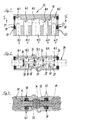
- the structure a tool for manufacturing the valve housing according to the Figure 1 or 2 is partially shown in Figure 3.
- FIG. 1 shows an example of the housing 10 pneumatic 5/2-way valve.
- This housing 10 is with a slide bore running along its longitudinal axis 12 provided, which completely penetrates the housing 10.
- the housing 10 has pressure medium channels 14.1 to 14.5, the blind hole in the slide bore 12th open out and to an outside of the housing 10 run.
- the pressure medium channels 14.1 to 14.5 in end there Connections, not shown, for contacting lines carrying pressure medium.
- the pressure medium channels 14.1 to 14.5, which counter to the Representation according to Figure 1 also on different outer sides of the housing can run, are at a distance arranged side by side and each end in one Working chamber 16.1 to 16.5.
- the latter are, like Figure 2 clearly shows in its dimensions compared to the Slider bore 12 expanded.
- Sealing devices 18 from two support disks 20 and an intermediate sealing ring 22 is arranged.
- valve slide 24 This is guided axially displaceably in the slide bore 12 and has seals 26 bearing cylinder sections 28 and intermediate and opposite in their outer diameter the cylinder sections 28 withdrawn Connection sections 30.
- the cylinder sections 28 separate in the basic position, not shown
- Directional control valve in operative connection with the seals 26 and Wall of the slide bore 12 two adjacent each Working chambers 16 from each other. If the valve slide 24, according to Figure 2, axially deflected so Pressure medium connections between two neighboring Working chambers 16, in Figure 2 as an example between the Working chambers 16.2 and 16.3 and the working chambers 16.4 and 16.5 opened by at least one of the Cylinder sections 28 out of engagement with the wall of the Slide bore 12 is brought.
- valve spool 24 For the sake of simplicity are the ends of the valve spool 24 as protruding outwards Cylinder shown. It actuates the Valve spool for switching the pressure medium connections between the working chambers 16. This actuation can mechanical, egg electromagnetic or pressure medium controlled respectively.
- the invention consists in a method of manufacture of a valve housing 10 designed in this way, without this lost kernels or machining to the Running areas of the seals 26 or on the control edges require.
- the method according to the invention stands out through the use of reusable inserts 32 ( Figure 3) made with the help of longitudinal or transverse slide be fixed in the tool during the process and in Connection to be pressed out of the valve housing 10.
- the insert parts 32 are concerned around sleeve-shaped components that rest on two longitudinal slides 34 of the tool at the beginning of the procedure.
- the longitudinal slide 34 equipped in this way forms the lateral one Part of the slide bore 12 are coaxial with each other Tool arranged, directed against each other and are in its outer diameter graduated several times at right angles.
- the smallest outer diameter is at the inner end formed a longitudinal slide 34 and takes the Inserts 32 on.
- the outer contour is below fluidic aspects largely free selectable, but must be at the end of the procedure to remove the Inserts 32 have an axial displacement in the direction of enable middle working chamber 16.3.
- a tool Cross slide 38 Simultaneously with the punch 36 is a tool Cross slide 38 introduced.
- the latter is in several parts executed and has two fork-shaped ends 40 on, which encompass the longitudinal slide 34.
- the cross slide 38 is at the end facing away from the punch 36 Inserts 32 arranged and clamped for axial fixation these inserts 32 between themselves and the punch 36.
- the outer contour of the insert parts 32 forms the running area the seals 26 of the valve slide 24 in the area between the working chambers 16.2 and 16.3 or 16.3 and 16.4; the Running area between the working chambers 16.1 and 16.2 or 16.4 and 16.5 of the corresponding contour section Longitudinal slide 34 determined.
- the shape of the working chambers 16.1 and 16.5 also specify the longitudinal slide 34 that the Working chambers 16.2 and 16.4, however, the cross slide 38 and that of the working chamber 16.3 of the stamp 36.
- Valve housing 10 made of all-plastic therefore inexpensive, compact and easy to manufacture.
- valve housing 10 not only in this way in plastic, but also in other materials, for example alloys made of light metal are.
- the invention is not for the manufacture of 5/2-way valves from the pneumatic application area limited.
Landscapes
- Engineering & Computer Science (AREA)
- Mechanical Engineering (AREA)
- Manufacturing & Machinery (AREA)
- Valve Housings (AREA)
- Multiple-Way Valves (AREA)
- Moulds For Moulding Plastics Or The Like (AREA)
- Sliding Valves (AREA)
Applications Claiming Priority (2)
| Application Number | Priority Date | Filing Date | Title |
|---|---|---|---|
| DE19909288A DE19909288A1 (de) | 1999-03-03 | 1999-03-03 | Verfahren zur spanlosen Herstellung eines Ventilgehäuses |
| DE19909288 | 1999-03-03 |
Publications (3)
| Publication Number | Publication Date |
|---|---|
| EP1033221A2 true EP1033221A2 (fr) | 2000-09-06 |
| EP1033221A3 EP1033221A3 (fr) | 2001-05-23 |
| EP1033221B1 EP1033221B1 (fr) | 2003-08-20 |
Family
ID=7899555
Family Applications (1)
| Application Number | Title | Priority Date | Filing Date |
|---|---|---|---|
| EP00103505A Expired - Lifetime EP1033221B1 (fr) | 1999-03-03 | 2000-02-18 | Procédé de fabrication d'un logement de soupape sans enlèvement de copeaux |
Country Status (3)
| Country | Link |
|---|---|
| EP (1) | EP1033221B1 (fr) |
| JP (1) | JP2000280301A (fr) |
| DE (2) | DE19909288A1 (fr) |
Cited By (1)
| Publication number | Priority date | Publication date | Assignee | Title |
|---|---|---|---|---|
| WO2013124102A1 (fr) * | 2012-02-23 | 2013-08-29 | Robert Bosch Gmbh | Procédé pour produire un carter en plastique |
Families Citing this family (4)
| Publication number | Priority date | Publication date | Assignee | Title |
|---|---|---|---|---|
| DE10120708A1 (de) | 2001-04-27 | 2002-10-31 | Bosch Gmbh Robert | Mehrwegeventilgehäuse |
| DE102005048622B4 (de) * | 2005-10-11 | 2010-09-02 | Festo Ag & Co. Kg | Steuerkolben, zugehöriges Herstellungsverfahren und damit ausgestattetes Ventil |
| JP7305280B2 (ja) * | 2019-11-15 | 2023-07-10 | ジヤトコ株式会社 | 樹脂製のバルブボディおよびその製造方法 |
| CN112776285B (zh) * | 2021-01-22 | 2022-10-28 | 乳源瑶族自治县旭荣玩具有限公司 | 一种包围壳体脱模机构 |
Citations (6)
| Publication number | Priority date | Publication date | Assignee | Title |
|---|---|---|---|---|
| FR1015307A (fr) * | 1950-03-29 | 1952-09-15 | Procédé de fabrication de revêtements de dimensions précises en une matière organique, telle par exemple que le caoutchouc, sur des corps métalliques et non métalliques | |
| JPH0199814A (ja) * | 1987-10-12 | 1989-04-18 | Tomiho:Kk | アンダーカット付き合成樹脂部材の成形方法 |
| DE9218270U1 (de) * | 1992-08-05 | 1993-10-21 | Mannesmann Ag | Vorrichtung zum Herstellen von hinterschnittenen Innenbohrungen in Ventilgehäusen der Wegeventil-Bauart |
| DE19729828A1 (de) * | 1997-07-11 | 1999-01-14 | Bosch Gmbh Robert | Verfahren zur Herstellung eines Mehrwegeventilgehäuses in Kunststoffspritzgießtechnik |
| EP0909912A2 (fr) * | 1997-10-16 | 1999-04-21 | Robert Bosch Gmbh | Robinet-vanne à voies multiples de plastique moulé par injection avec des éléments de guidage integrés |
| EP0924451A1 (fr) * | 1997-12-20 | 1999-06-23 | Robert Bosch Gmbh | Distributeur |
Family Cites Families (2)
| Publication number | Priority date | Publication date | Assignee | Title |
|---|---|---|---|---|
| DE718246C (de) * | 1940-05-30 | 1942-03-06 | Mahle Kg | Mehrteiliger Kern |
| FR2409843A1 (fr) * | 1977-11-29 | 1979-06-22 | Michelin & Cie | Moule pour objets ayant des parties en contre-depouille |
-
1999
- 1999-03-03 DE DE19909288A patent/DE19909288A1/de not_active Ceased
-
2000
- 2000-02-18 DE DE50003325T patent/DE50003325D1/de not_active Expired - Fee Related
- 2000-02-18 EP EP00103505A patent/EP1033221B1/fr not_active Expired - Lifetime
- 2000-03-03 JP JP2000059247A patent/JP2000280301A/ja active Pending
Patent Citations (6)
| Publication number | Priority date | Publication date | Assignee | Title |
|---|---|---|---|---|
| FR1015307A (fr) * | 1950-03-29 | 1952-09-15 | Procédé de fabrication de revêtements de dimensions précises en une matière organique, telle par exemple que le caoutchouc, sur des corps métalliques et non métalliques | |
| JPH0199814A (ja) * | 1987-10-12 | 1989-04-18 | Tomiho:Kk | アンダーカット付き合成樹脂部材の成形方法 |
| DE9218270U1 (de) * | 1992-08-05 | 1993-10-21 | Mannesmann Ag | Vorrichtung zum Herstellen von hinterschnittenen Innenbohrungen in Ventilgehäusen der Wegeventil-Bauart |
| DE19729828A1 (de) * | 1997-07-11 | 1999-01-14 | Bosch Gmbh Robert | Verfahren zur Herstellung eines Mehrwegeventilgehäuses in Kunststoffspritzgießtechnik |
| EP0909912A2 (fr) * | 1997-10-16 | 1999-04-21 | Robert Bosch Gmbh | Robinet-vanne à voies multiples de plastique moulé par injection avec des éléments de guidage integrés |
| EP0924451A1 (fr) * | 1997-12-20 | 1999-06-23 | Robert Bosch Gmbh | Distributeur |
Non-Patent Citations (1)
| Title |
|---|
| PATENT ABSTRACTS OF JAPAN vol. 013, no. 311 (M-851), 17. Juli 1989 (1989-07-17) -& JP 01 099814 A (TOMIHO:KK), 18. April 1989 (1989-04-18) * |
Cited By (3)
| Publication number | Priority date | Publication date | Assignee | Title |
|---|---|---|---|---|
| WO2013124102A1 (fr) * | 2012-02-23 | 2013-08-29 | Robert Bosch Gmbh | Procédé pour produire un carter en plastique |
| CN104144776A (zh) * | 2012-02-23 | 2014-11-12 | 罗伯特·博世有限公司 | 用于制造塑料壳体的方法 |
| CN104144776B (zh) * | 2012-02-23 | 2017-04-26 | 罗伯特·博世有限公司 | 用于制造塑料壳体的方法 |
Also Published As
| Publication number | Publication date |
|---|---|
| JP2000280301A (ja) | 2000-10-10 |
| EP1033221A3 (fr) | 2001-05-23 |
| DE19909288A1 (de) | 2000-09-07 |
| DE50003325D1 (de) | 2003-09-25 |
| EP1033221B1 (fr) | 2003-08-20 |
Similar Documents
| Publication | Publication Date | Title |
|---|---|---|
| EP1073070B1 (fr) | Electro-aimant et soupape hydraulique comprenant un électro-aimant | |
| DE2751946C2 (de) | Druckmittelverteiler | |
| EP0761336A1 (fr) | Méthode et appareil de fabrication d'un collecteur | |
| DE2844475A1 (de) | Radialpresse fuer werkstuecke mit zylindrischer aussenflaeche mit mehreren, im kreis angeordneten pressbacken | |
| DE4101059A1 (de) | Dichtungseinrichtung fuer ein mehrwegeventil sowie verfahren zu ihrer herstellung | |
| WO2006128519A1 (fr) | Dispositif et procede de formage par explosion | |
| DE102005040276A1 (de) | Verfahren zum Schmieden von Radnaben-Rohlingen auf einer Druckumformmaschine | |
| DE1947117B2 (de) | Verfahren zum herstellen eines ventilschiebers | |
| DE3739425A1 (de) | Dichtungsanordnung sowie verfahren zu ihrer herstellung | |
| EP0425981A2 (fr) | Bloc à canaux de chauffe | |
| DE2557416A1 (de) | Verfahren und vorrichtung zum herstellen eines rohrverbinders mit radialer erweiterung | |
| EP1033221B1 (fr) | Procédé de fabrication d'un logement de soupape sans enlèvement de copeaux | |
| DE3204112C2 (de) | Servo-Schieberventil | |
| DE102004003893A1 (de) | Schieber für ein Schieberventil sowie Verfahren und Formwerkzeug zum Herstellen eines Schiebers | |
| EP1734253B1 (fr) | Soupape d'injection avec manchon et méthode de sa production | |
| DE19729828B4 (de) | Werkzeug zur Herstellung eines Mehrwegeventilgehäuses in Kunststoffspritzgießtechnik | |
| DE4416726C2 (de) | Kolben-Zylinder-Einheit und Verfahren zur Herstellung einer Kolben-Zylinder-Einheit | |
| DE19743863A1 (de) | Verfahren und Vorrichtung zum Herstellen einer Hohlwelle mit äußeren radialen Erhebungen durch Innenhochdruck-Umformung | |
| DE19748345C2 (de) | Schieberventil | |
| DE102017121136A1 (de) | Steuerkolben aus Kunststoff, Werkzeug und Verfahren zur Herstellung eines Steuerkolbens | |
| DE10313812B3 (de) | Verfahren und Vorrichtung zur Herstellung einer gebauten Nockenwelle | |
| DE3713105A1 (de) | Zungendruckmittler und verfahren zum herstellen eines zungendruckmittlers | |
| DE4133340A1 (de) | Kondensatorbechergehaeuse mit sollberstbereich sowie verfahren und werkzeug zu seiner herstellung | |
| DE19523420C1 (de) | Hydraulische Formschließvorrichtung für eine Spritzgießmaschine | |
| DE3106378A1 (de) | "pneumatische ausgleichsfederanordnung sowie verfahren und vorrichtung zu ihrer herstellung" |
Legal Events
| Date | Code | Title | Description |
|---|---|---|---|
| PUAI | Public reference made under article 153(3) epc to a published international application that has entered the european phase |
Free format text: ORIGINAL CODE: 0009012 |
|
| AK | Designated contracting states |
Kind code of ref document: A2 Designated state(s): CH DE FR GB LI |
|
| AX | Request for extension of the european patent |
Free format text: AL;LT;LV;MK;RO;SI |
|
| PUAL | Search report despatched |
Free format text: ORIGINAL CODE: 0009013 |
|
| AK | Designated contracting states |
Kind code of ref document: A3 Designated state(s): AT BE CH CY DE DK ES FI FR GB GR IE IT LI LU MC NL PT SE |
|
| AX | Request for extension of the european patent |
Free format text: AL;LT;LV;MK;RO;SI |
|
| RIC1 | Information provided on ipc code assigned before grant |
Free format text: 7B 29C 33/44 A, 7B 29C 45/44 B, 7B 29L 22/00 B, 7B 29C 45/40 B, 7B 29C 33/48 B |
|
| 17P | Request for examination filed |
Effective date: 20011123 |
|
| AKX | Designation fees paid |
Free format text: CH DE FR GB LI |
|
| 17Q | First examination report despatched |
Effective date: 20020529 |
|
| GRAH | Despatch of communication of intention to grant a patent |
Free format text: ORIGINAL CODE: EPIDOS IGRA |
|
| GRAS | Grant fee paid |
Free format text: ORIGINAL CODE: EPIDOSNIGR3 |
|
| GRAA | (expected) grant |
Free format text: ORIGINAL CODE: 0009210 |
|
| AK | Designated contracting states |
Designated state(s): CH DE FR GB LI |
|
| PG25 | Lapsed in a contracting state [announced via postgrant information from national office to epo] |
Ref country code: GB Free format text: LAPSE BECAUSE OF FAILURE TO SUBMIT A TRANSLATION OF THE DESCRIPTION OR TO PAY THE FEE WITHIN THE PRESCRIBED TIME-LIMIT Effective date: 20030820 |
|
| REG | Reference to a national code |
Ref country code: GB Ref legal event code: FG4D Free format text: NOT ENGLISH |
|
| REG | Reference to a national code |
Ref country code: CH Ref legal event code: EP |
|
| REF | Corresponds to: |
Ref document number: 50003325 Country of ref document: DE Date of ref document: 20030925 Kind code of ref document: P |
|
| GBV | Gb: ep patent (uk) treated as always having been void in accordance with gb section 77(7)/1977 [no translation filed] |
Effective date: 20030820 |
|
| PG25 | Lapsed in a contracting state [announced via postgrant information from national office to epo] |
Ref country code: LI Free format text: LAPSE BECAUSE OF NON-PAYMENT OF DUE FEES Effective date: 20040229 Ref country code: CH Free format text: LAPSE BECAUSE OF NON-PAYMENT OF DUE FEES Effective date: 20040229 |
|
| ET | Fr: translation filed | ||
| PLBE | No opposition filed within time limit |
Free format text: ORIGINAL CODE: 0009261 |
|
| STAA | Information on the status of an ep patent application or granted ep patent |
Free format text: STATUS: NO OPPOSITION FILED WITHIN TIME LIMIT |
|
| 26N | No opposition filed |
Effective date: 20040524 |
|
| REG | Reference to a national code |
Ref country code: CH Ref legal event code: PL |
|
| PGFP | Annual fee paid to national office [announced via postgrant information from national office to epo] |
Ref country code: DE Payment date: 20060214 Year of fee payment: 7 |
|
| PGFP | Annual fee paid to national office [announced via postgrant information from national office to epo] |
Ref country code: FR Payment date: 20060216 Year of fee payment: 7 |
|
| REG | Reference to a national code |
Ref country code: FR Ref legal event code: ST Effective date: 20071030 |
|
| PG25 | Lapsed in a contracting state [announced via postgrant information from national office to epo] |
Ref country code: DE Free format text: LAPSE BECAUSE OF NON-PAYMENT OF DUE FEES Effective date: 20070901 |
|
| PG25 | Lapsed in a contracting state [announced via postgrant information from national office to epo] |
Ref country code: FR Free format text: LAPSE BECAUSE OF NON-PAYMENT OF DUE FEES Effective date: 20070228 |