EP1033221A2 - Method for producing a valve housing without cutting - Google Patents
Method for producing a valve housing without cutting Download PDFInfo
- Publication number
- EP1033221A2 EP1033221A2 EP00103505A EP00103505A EP1033221A2 EP 1033221 A2 EP1033221 A2 EP 1033221A2 EP 00103505 A EP00103505 A EP 00103505A EP 00103505 A EP00103505 A EP 00103505A EP 1033221 A2 EP1033221 A2 EP 1033221A2
- Authority
- EP
- European Patent Office
- Prior art keywords
- slide
- longitudinal
- slides
- valve
- stamp
- Prior art date
- Legal status (The legal status is an assumption and is not a legal conclusion. Google has not performed a legal analysis and makes no representation as to the accuracy of the status listed.)
- Granted
Links
Images
Classifications
-
- B—PERFORMING OPERATIONS; TRANSPORTING
- B29—WORKING OF PLASTICS; WORKING OF SUBSTANCES IN A PLASTIC STATE IN GENERAL
- B29C—SHAPING OR JOINING OF PLASTICS; SHAPING OF MATERIAL IN A PLASTIC STATE, NOT OTHERWISE PROVIDED FOR; AFTER-TREATMENT OF THE SHAPED PRODUCTS, e.g. REPAIRING
- B29C33/00—Moulds or cores; Details thereof or accessories therefor
- B29C33/44—Moulds or cores; Details thereof or accessories therefor with means for, or specially constructed to facilitate, the removal of articles, e.g. of undercut articles
- B29C33/48—Moulds or cores; Details thereof or accessories therefor with means for, or specially constructed to facilitate, the removal of articles, e.g. of undercut articles with means for collapsing or disassembling
- B29C33/485—Moulds or cores; Details thereof or accessories therefor with means for, or specially constructed to facilitate, the removal of articles, e.g. of undercut articles with means for collapsing or disassembling cores or mandrels
-
- B—PERFORMING OPERATIONS; TRANSPORTING
- B29—WORKING OF PLASTICS; WORKING OF SUBSTANCES IN A PLASTIC STATE IN GENERAL
- B29C—SHAPING OR JOINING OF PLASTICS; SHAPING OF MATERIAL IN A PLASTIC STATE, NOT OTHERWISE PROVIDED FOR; AFTER-TREATMENT OF THE SHAPED PRODUCTS, e.g. REPAIRING
- B29C45/00—Injection moulding, i.e. forcing the required volume of moulding material through a nozzle into a closed mould; Apparatus therefor
- B29C45/17—Component parts, details or accessories; Auxiliary operations
- B29C45/40—Removing or ejecting moulded articles
- B29C45/44—Removing or ejecting moulded articles for undercut articles
- B29C45/4478—Removing or ejecting moulded articles for undercut articles using non-rigid undercut forming elements, e.g. elastic or resilient
-
- B—PERFORMING OPERATIONS; TRANSPORTING
- B29—WORKING OF PLASTICS; WORKING OF SUBSTANCES IN A PLASTIC STATE IN GENERAL
- B29L—INDEXING SCHEME ASSOCIATED WITH SUBCLASS B29C, RELATING TO PARTICULAR ARTICLES
- B29L2031/00—Other particular articles
- B29L2031/748—Machines or parts thereof not otherwise provided for
- B29L2031/7506—Valves
Abstract
Description
Die Erfindung geht aus von einem Verfahren zur spanlosen Herstellung eines Ventilgehäuses entsprechend der Gattung des Anspruchs 1. Ein derartiges Verfahren ist beispielsweise aus der DE 197 29 828 A1 bereits bekannt. Bei diesem Verfahren wird zumindest ein Teil des Gehäuseinneren mit Hilfe eines Schmelzkerns hergestellt. Dieser Schmelzkern wird von einem Werkzeugstempel in der Spritzgußform gehalten und wird am Verfahrensende ausgeschmolzen. Dieses Ausschmelzen ist kostenintensiv und kann infolge von Wärmespannungen im Ventilgehäuse zu Verzug führen.The invention is based on a method for non-cutting Manufacture of a valve housing according to the genus of claim 1. Such a method is for example already known from DE 197 29 828 A1. With this The process involves using at least part of the interior of the housing Made with the help of a melting core. This melting core is held in the injection mold by a tool stamp and is melted out at the end of the process. This Melting is costly and can result from Thermal stresses in the valve housing lead to warpage.
Die Erfindung mit den kennzeichnenden Merkmalen des Anspruchs 1 weist demgegenüber den Vorteil auf, daß mit Hilfe von wieder verwendbaren Einlegeteilen auf den Einsatz von Schmelzkernen verzichtet werden kann. Das vorgeschlagene Verfahren bildet die Grundlage zur Herstellung von Ventilgehäusen in Kunststoff ohne thermische Nachbehandlung. Die Ausbildung von Steuerkanten und Dichtflächen ist dabei ohne mechanische Bearbeitung möglich. Die für das erfindungsgemäße Verfahren eingesetzten Werkzeuge haben ein hohes Stückzahlpotential bei geringem Investitionsaufwand. Dies senkt die Fertigungskosten, insbesondere im Vergleich zur bekannten voll- bzw. teilmechanischen Herstellung. Die auf diese Weise hergestellten Ventilgehäuse zeichnen durch einen hohen Durchfluß und ihre kompakte Bauweise aus, sind korrosionsfest und haben ein geringes Gewicht. Aufgrund der geringen Anzahl von Dichtstellen haben diese Ventilgehäuse eine verhältnismäßig hohe Dichtheit gegen Druckmittelleckage. Wegeventile mit derartig hergestellten Gehäusen bestehen aus wenigen Einzelteilen und lassen sich einfach montieren.The invention with the characterizing features of Claim 1 has the advantage that with Help of reusable inserts on the insert melting cores can be dispensed with. The proposed Process forms the basis for the production of Valve housings in plastic without thermal aftertreatment. The formation of control edges and sealing surfaces is included possible without mechanical processing. The one for that Tools used according to the method of the invention high quantity potential with low investment. This lowers manufacturing costs, especially when compared for the well-known fully or partially mechanical production. The Valve housings produced in this way are characterized by a high flow rate and their compact design are corrosion-resistant and light in weight. Due to the These valve housings have a small number of sealing points a relatively high tightness against Fluid leakage. Directional valves with such manufactured Housings consist of a few individual parts and can be easy to assemble.
Weitere Vorteile oder vorteilhafte Weiterbildungen der Erfindung ergeben sich aus den Unteransprüchen oder der Beschreibung.Further advantages or advantageous developments of Invention result from the dependent claims or the Description.
Die Erfindung ist anhand der Zeichnung dargestellt und wird im Folgenden näher erläutert.The invention is illustrated by the drawing and will explained in more detail below.
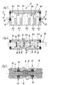
Ein gemäß dem beanspruchten Verfahren hergestelltes Ventilgehäuse ist in Figur 1 im Längsschnitt gezeichnet. Einen Querschnitt durch ein Ventilgehäuse entlang der Linie II-II nach Figur 1 zeigt die Figur 2, wobei hier in das Ventilgehäuse ein Steuerschieber eingebaut ist. Der Aufbau eines Werkzeugs zur Herstellung des Ventilgehäuses gemäß den Figuren 1 oder 2 ist in der Figur 3 teilweise dargestellt.A manufactured according to the claimed method Valve housing is drawn in longitudinal section in FIG. 1. A cross section through a valve housing along the line II-II of Figure 1 shows Figure 2, with here in the A valve spool is installed in the valve housing. The structure a tool for manufacturing the valve housing according to the Figure 1 or 2 is partially shown in Figure 3.
Figur 1 zeigt exemplarisch das Gehäuse 10 eines
pneumatischen 5/2-Wegeventils. Dieses Gehäuse 10 ist mit
einer entlang seiner Längsachse verlaufenden Schieberbohrung
12 versehen, die das Gehäuse 10 vollständig durchdringt. Figure 1 shows an example of the housing 10
pneumatic 5/2-way valve. This housing 10 is with
a slide bore running along its
Darüber hinaus weist das Gehäuse 10 Druckmittelkanäle 14.1 bis 14.5 auf, die sacklochartig in die Schieberbohrung 12 einmünden und zu einer Außenseite des Gehäuses 10 hin verlaufen. Dort enden die Druckmittelkanäle 14.1 bis 14.5 in nicht dargestellten Anschlüssen zur Kontaktierung mit druckmittelführenden Leitungen.In addition, the housing 10 has pressure medium channels 14.1 to 14.5, the blind hole in the slide bore 12th open out and to an outside of the housing 10 run. The pressure medium channels 14.1 to 14.5 in end there Connections, not shown, for contacting lines carrying pressure medium.
Die Druckmittelkanäle 14.1 bis 14.5, die entgegen der
Darstellung nach Figur 1 auch zu verschiedenen Außenseiten
des Gehäuses hin verlaufen können, sind mit Abstand
nebeneinander angeordnet und enden jeweils in einer
Arbeitskammer 16.1 bis 16.5. Letztere sind, wie Figur 2
deutlich zeigt, in ihren Abmessungen gegenüber der
Schieberbohrung 12 erweitert. In den beiden stirnseitigen
Endabschnitten der Schieberbohrung 12 sind
Dichtungseinrichtungen 18 aus zwei Stützscheiben 20 und
einem dazwischen liegenden Dichtring 22 angeordnet.The pressure medium channels 14.1 to 14.5, which counter to the
Representation according to Figure 1 also on different outer sides
of the housing can run, are at a distance
arranged side by side and each end in one
Working chamber 16.1 to 16.5. The latter are, like Figure 2
clearly shows in its dimensions compared to the
Diese Dichtungseinrichtungen 18 wirken, wie in Figur 2
gezeigt ist, mit einem Ventilschieber 24 zusammen. Dieser
ist axial verschiebbar in der Schieberbohrung 12 geführt und
weist Dichtungen 26 tragende Zylinderabschnitte 28 und
dazwischen liegende und in ihrem Außendurchmesser gegenüber
den Zylinderabschnitten 28 zurückgenommene
Verbindungsabschnitte 30 auf. Die Zylinderabschnitte 28
trennen in der nicht dargestellten Grundstellung des
Wegeventils in Wirkverbindung mit den Dichtungen 26 und der
Wandung der Schieberbohrung 12 jeweils zwei benachbarte
Arbeitskammern 16 voneinander. Wird der Ventilschieber 24,
gemäß Figur 2, axial ausgelenkt, so werden
Druckmittelverbindungen zwischen zwei benachbarten
Arbeitskammern 16, in Figur 2 beispielhaft zwischen den
Arbeitskammern 16.2 und 16.3 sowie den Arbeitskammern 16.4
und 16.5 geöffnet, indem wenigstens einer der
Zylinderabschnitte 28 außer Eingriff mit der Wandung der
Schieberbohrung 12 gebracht wird. Der Einfachheit halber
sind die Enden des Ventilschiebers 24 als nach außen ragende
Zylinder dargestellt. Über sie erfolgt eine Betätigung des
Ventilschiebers zur Umschaltung der Druckmittelverbindungen
zwischen den Arbeitskammern 16. Diese Betätigung kann
mechanisch, ei elektromagnetisch oder druckmittelgesteuert
erfolgen.These
Eine der maßgeblichen Kenngrößen eines Wegeventils ist
dessen maximaler Druckmitteldurchsatz. Dieser läßt sich
durch eine strömungstechnisch günstige Formgebung der
Wandung der Arbeitskammern 16 verbessern. Im dargestellten
Gehäuse nach Figur 1 weist deshalb die dem Zulauf
zugeordnete mittlere Arbeitskammer 16.3 einen
Freiformquerschnitt mit besonders stark abgerundeten
Steuerkanten am Übergang zur Schieberbohrung 12 auf.
Seitlich zu dieser zulaufseitigen Arbeitskammer 16.3 sind
die beiden den Verbrauchern A und B zugeordneten
Arbeitskammern 16.2 und 16.4 plaziert; die dem Rücklauf R
zugeordneten Arbeitskammern 16.1 und 16.5 liegen jeweils
benachbart dazu im stirnseitigen Bereich des Ventilgehäuses
10.One of the key parameters of a directional control valve is
its maximum fluid flow. This can be
due to the aerodynamically favorable shape of the
Improve the wall of the working chambers 16. In the illustrated
Housing according to Figure 1 therefore has the inlet
assigned middle working chamber 16.3 one
Free-form cross-section with a particularly rounded shape
Control edges at the transition to the
Die Erfindung besteht in einem Verfahren zur Herstellung
eines derart ausgebildeten Ventilgehäuses 10, ohne dazu
verlorene Kerne oder eine spanende Nachbearbeitung an den
Laufbereichen der Dichtungen 26 oder an den Steuerkanten zu
erfordern. Das erfindungsgemäße Verfahren zeichnet sich
durch die Verwendung von wiederverwendbaren Einlegeteilen 32
(Figur 3) aus, die mit Hilfe von Längs- bzw. Querschiebern
während des Verfahrens im Werkzeug fixiert werden und im
Anschluß daran aus dem Ventilgehäuse 10 ausgepreßt werden.The invention consists in a method of manufacture
of a valve housing 10 designed in this way, without this
lost kernels or machining to the
Running areas of the
Wie Figur 3 zeigt, handelt es sich bei den Einlegeteilen 32
um hülsenförmige Bauelemente, die auf zwei Längsschiebern 34
des Werkzeugs zu Beginn des Verfahrens aufgeschoben werden.
Die derart bestückten Längsschieber 34 formen den seitlichen
Teil der Schieberbohrung 12 aus, sind koaxial zueinander im
Werkzeug angeordnet, gegeneinander gerichtet und sind in
ihrem Außendurchmesser mehrfach rechtwinklig abgestuft. Der
kleinste Außendurchmesser ist am jeweils innenliegenden Ende
eines Längsschiebers 34 ausgebildet und nimmt die
Einlegeteile 32 auf. Deren Außenkontur ist unter
strömungstechnischen Gesichtspunkten weitgehend frei
wählbar, muß aber am Verfahrensende zur Entfernung der
Einlegeteile 32 eine axiale Verschiebbarkeit in Richtung der
mittleren Arbeitskammer 16.3 ermöglichen.As FIG. 3 shows, the
In der Schließstellung des Werkzeugs besteht zwischen den
einander zugewandten Stirnflächen der beiden Längsschieber
34 ein Abstand, in den ein die Außenkontur der Arbeitskammer
16.3 formender, quer im Werkzeug geführter Stempel 36
eingeschoben wird. Der Stempel 36 ist dabei so bemessen, daß
seine Ausdehnung sowohl in radialer als auch in axialer
Richtung größer ist als die entsprechenden Abmessungen eines
Einlegeteils 32.In the closed position of the tool there is between the
mutually facing end faces of the two longitudinal slides
34 a distance into which the outer contour of the working chamber
16.3 forming
An den Seitenflächen dieses Stempels 36 stützen sich die
Längsschieber 34 und die Einlegeteile 32 ab.The are supported on the side surfaces of this
Gleichzeitig mit den Stempel 36 wird in das Werkzeug ein
Querschieber 38 eingeführt. Letzterer ist mehrteilig
ausgeführt und weist zwei gabelförmig ausgebildete Enden 40
auf, die den Längsschieber 34 umgreifen. Der Querschieber 38
ist an dem vom Stempel 36 abgewandt liegenden Ende der
Einlegeteile 32 angeordnet und spannt zur axialen Fixierung
diese Einlegeteile 32 zwischen sich und den Stempel 36 ein.Simultaneously with the
Die Außenkontur der Einlegeteile 32 formt den Laufbereich
der Dichtungen 26 des Ventilschiebers 24 im Bereich zwischen
den Arbeitskammern 16.2 und 16.3 bzw. 16.3 und 16.4; der
Laufbereich zwischen den Arbeitskammern 16.1 und 16.2 bzw.
16.4 und 16.5 wird vom entsprechenden Konturabschnitt der
Längsschieber 34 bestimmt. Die Form der Arbeitskammern 16.1
und 16.5 geben ebenfalls die Längsschieber 34 vor, die der
Arbeitskammern 16.2 und 16.4 dagegen die Querschieber 38 und
die der Arbeitskammer 16.3 der Stempel 36.The outer contour of the
Nach der Formgebung des Gehäuses 10 werden der Stempel 36
und der Querschieber 38 gezogen, danach folgen die
Längsschieber 34. Die Einlegeteile 32 verbleiben dabei im
Ventilgehäuse 10. Durch Ziehen des zentralen Stempels 36 ist
ausreichend Raum im Gehäuse 10 vorhanden, um diese
Einlegeteile 32 auszupressen. Dies erfolgt in einem
separaten Verfahrensschritt, bei dem durch die
Schieberbohrung 12 eine Auspreßvorrichtung ins Ventilgehäuse
10 eingeführt wird, die die Einlegeteile in Richtung der vom
Stempel 36 geformten Arbeitskammer 16.3 drückt. Die so
entfernten Einlegeteile 32 können beim nächsten
Spritzvorgang wieder verwendet werden.After the shape of the housing 10, the
Durch die mehrteilige Ausführung der Querschieber 38 können
die Strömungskanten am Übergang von den Arbeitskammern 16.2
und 16.4 in die Schieberbohrung 12 gerundet und damit der
Durchfluß und die Montierbarkeit des Ventilschiebers 24
verbessert werden. Die Laufflächen der Dichtungen 26 des
Ventilschiebers 24 und die Steuerkanten werden
funktionsfertig, d.h. ohne mechanische Nachbearbeitung
hergestellt. Ventilgehäuse 10 aus Vollkunststoff lassen sich
dadurch kostengünstig, kompakt und einfach herstellen.Due to the multi-part design of the
Selbstverständlich sind Änderungen oder Ergänzungen an den beschriebenen Gegenständen bzw. Verfahren möglich, ohne vom Grundgedanken der Erfindung abzuweichen. Diesbezüglich ist anzumerken, daß Ventilgehäuse 10 auf diese Weise nicht nur in Kunststoff, sondern auch in anderen Materialien, beispielsweise Legierungen aus Leichtmetall, herstellbar sind. Ebenso ist die Erfindung nicht auf die Herstellung von 5/2-Wegeventilen aus dem pneumatischen Anwendungsbereich eingeschränkt.Of course, changes or additions to the described objects or procedures possible without the Deviate basic ideas of the invention. In this regard note that valve housing 10 not only in this way in plastic, but also in other materials, for example alloys made of light metal are. Likewise, the invention is not for the manufacture of 5/2-way valves from the pneumatic application area limited.
Claims (9)
Applications Claiming Priority (2)
| Application Number | Priority Date | Filing Date | Title |
|---|---|---|---|
| DE19909288A DE19909288A1 (en) | 1999-03-03 | 1999-03-03 | Process for the non-cutting production of a valve housing |
| DE19909288 | 1999-03-03 |
Publications (3)
| Publication Number | Publication Date |
|---|---|
| EP1033221A2 true EP1033221A2 (en) | 2000-09-06 |
| EP1033221A3 EP1033221A3 (en) | 2001-05-23 |
| EP1033221B1 EP1033221B1 (en) | 2003-08-20 |
Family
ID=7899555
Family Applications (1)
| Application Number | Title | Priority Date | Filing Date |
|---|---|---|---|
| EP00103505A Expired - Lifetime EP1033221B1 (en) | 1999-03-03 | 2000-02-18 | Method for producing a valve housing without cutting |
Country Status (3)
| Country | Link |
|---|---|
| EP (1) | EP1033221B1 (en) |
| JP (1) | JP2000280301A (en) |
| DE (2) | DE19909288A1 (en) |
Cited By (1)
| Publication number | Priority date | Publication date | Assignee | Title |
|---|---|---|---|---|
| WO2013124102A1 (en) * | 2012-02-23 | 2013-08-29 | Robert Bosch Gmbh | Method for producing a plastic housing |
Families Citing this family (4)
| Publication number | Priority date | Publication date | Assignee | Title |
|---|---|---|---|---|
| DE10120708A1 (en) | 2001-04-27 | 2002-10-31 | Bosch Gmbh Robert | Multiway valve housing |
| DE102005048622B4 (en) * | 2005-10-11 | 2010-09-02 | Festo Ag & Co. Kg | Control piston, related manufacturing process and valve equipped therewith |
| JP7305280B2 (en) | 2019-11-15 | 2023-07-10 | ジヤトコ株式会社 | Resin valve body and manufacturing method thereof |
| CN112776285B (en) * | 2021-01-22 | 2022-10-28 | 乳源瑶族自治县旭荣玩具有限公司 | Surrounding shell demolding mechanism |
Citations (6)
| Publication number | Priority date | Publication date | Assignee | Title |
|---|---|---|---|---|
| FR1015307A (en) * | 1950-03-29 | 1952-09-15 | Method of manufacturing precisely dimensioned coatings of an organic material, such as for example rubber, on metallic and non-metallic bodies | |
| JPH0199814A (en) * | 1987-10-12 | 1989-04-18 | Tomiho:Kk | Molding method for synthetic resin member with undercut |
| DE9218270U1 (en) * | 1992-08-05 | 1993-10-21 | Mannesmann Ag | Device for producing undercut internal bores in valve housings of the directional valve type |
| DE19729828A1 (en) * | 1997-07-11 | 1999-01-14 | Bosch Gmbh Robert | Injection moulding tool for plastic multi=way slide valve housing |
| EP0909912A2 (en) * | 1997-10-16 | 1999-04-21 | Robert Bosch Gmbh | Injection moulded plastic multiple way valve housing with integrated guiding elements |
| EP0924451A1 (en) * | 1997-12-20 | 1999-06-23 | Robert Bosch Gmbh | Directional valve |
Family Cites Families (2)
| Publication number | Priority date | Publication date | Assignee | Title |
|---|---|---|---|---|
| DE718246C (en) * | 1940-05-30 | 1942-03-06 | Mahle Kg | Multipart core |
| FR2409843A1 (en) * | 1977-11-29 | 1979-06-22 | Michelin & Cie | MOLD FOR OBJECTS WITH LOCKED PARTS |
-
1999
- 1999-03-03 DE DE19909288A patent/DE19909288A1/en not_active Ceased
-
2000
- 2000-02-18 EP EP00103505A patent/EP1033221B1/en not_active Expired - Lifetime
- 2000-02-18 DE DE50003325T patent/DE50003325D1/en not_active Expired - Fee Related
- 2000-03-03 JP JP2000059247A patent/JP2000280301A/en active Pending
Patent Citations (6)
| Publication number | Priority date | Publication date | Assignee | Title |
|---|---|---|---|---|
| FR1015307A (en) * | 1950-03-29 | 1952-09-15 | Method of manufacturing precisely dimensioned coatings of an organic material, such as for example rubber, on metallic and non-metallic bodies | |
| JPH0199814A (en) * | 1987-10-12 | 1989-04-18 | Tomiho:Kk | Molding method for synthetic resin member with undercut |
| DE9218270U1 (en) * | 1992-08-05 | 1993-10-21 | Mannesmann Ag | Device for producing undercut internal bores in valve housings of the directional valve type |
| DE19729828A1 (en) * | 1997-07-11 | 1999-01-14 | Bosch Gmbh Robert | Injection moulding tool for plastic multi=way slide valve housing |
| EP0909912A2 (en) * | 1997-10-16 | 1999-04-21 | Robert Bosch Gmbh | Injection moulded plastic multiple way valve housing with integrated guiding elements |
| EP0924451A1 (en) * | 1997-12-20 | 1999-06-23 | Robert Bosch Gmbh | Directional valve |
Non-Patent Citations (1)
| Title |
|---|
| PATENT ABSTRACTS OF JAPAN vol. 013, no. 311 (M-851), 17. Juli 1989 (1989-07-17) -& JP 01 099814 A (TOMIHO:KK), 18. April 1989 (1989-04-18) * |
Cited By (3)
| Publication number | Priority date | Publication date | Assignee | Title |
|---|---|---|---|---|
| WO2013124102A1 (en) * | 2012-02-23 | 2013-08-29 | Robert Bosch Gmbh | Method for producing a plastic housing |
| CN104144776A (en) * | 2012-02-23 | 2014-11-12 | 罗伯特·博世有限公司 | Method for producing a plastic housing |
| CN104144776B (en) * | 2012-02-23 | 2017-04-26 | 罗伯特·博世有限公司 | Method for producing a plastic housing |
Also Published As
| Publication number | Publication date |
|---|---|
| EP1033221A3 (en) | 2001-05-23 |
| EP1033221B1 (en) | 2003-08-20 |
| DE19909288A1 (en) | 2000-09-07 |
| DE50003325D1 (en) | 2003-09-25 |
| JP2000280301A (en) | 2000-10-10 |
Similar Documents
| Publication | Publication Date | Title |
|---|---|---|
| EP1073070B1 (en) | Electromagnet and hydraulic valve comprising an electromagnet | |
| DE2751946C2 (en) | Pressure fluid distributor | |
| EP0761336A1 (en) | Method and apparatus for producing a unitary manifold | |
| DE2844475A1 (en) | RADIAL PRESS FOR WORKPIECES WITH CYLINDRICAL OUTER SURFACE WITH SEVERAL PRESS JAWS IN A CIRCLE | |
| DE4101059A1 (en) | SEALING DEVICE FOR A MULTI-WAY VALVE AND METHOD FOR THEIR PRODUCTION | |
| WO2006128519A1 (en) | Device and method for explosion forming | |
| DE102005040276A1 (en) | Method for forging wheel hub blanks on a pressure forming machine | |
| DE1947117B2 (en) | METHOD OF MANUFACTURING A VALVE VALVE | |
| DE3739425A1 (en) | SEALING ARRANGEMENT AND METHOD FOR THEIR PRODUCTION | |
| EP0425981A2 (en) | Hot runner block | |
| DE2557416A1 (en) | METHOD AND APPARATUS FOR MANUFACTURING A PIPE CONNECTOR WITH RADIAL EXPANSION | |
| EP1033221B1 (en) | Method for producing a valve housing without cutting | |
| DE3204112C2 (en) | Servo slide valve | |
| DE102004003893A1 (en) | Slide for slide valve has section guided in bore and ending in control edge through which it merges into smaller diameter section, and from control edge extends notch formed in outer face of larger diameter section and running into point | |
| EP1734253B1 (en) | Injection valve with housing and method for producing said housing | |
| DE19729828B4 (en) | Tool for producing a multi-way valve housing in plastic injection molding technology | |
| DE4416726C2 (en) | Piston-cylinder unit and method for producing a piston-cylinder unit | |
| DE19743863A1 (en) | Method and device for producing a hollow shaft with external radial elevations by hydroforming | |
| DE19748345C2 (en) | Slide valve | |
| DE102017121136A1 (en) | Plastic control piston, tool and method of manufacturing a control piston | |
| DE10313812B3 (en) | Method and device for producing a built camshaft | |
| DE3713105A1 (en) | Reed-type pressure transmitter and method for producing a reed-type pressure transmitter | |
| DE4133340A1 (en) | Capacitor can with burst section - has cup shaped housing formed in press extrusion process with die having insert to form grooves for burst section | |
| DE19523420C1 (en) | Injection moulding machine tool closure system with hydraulic pressure transmission unit | |
| DE3106378A1 (en) | "PNEUMATIC COMPENSATING SPRING ARRANGEMENT AND METHOD AND DEVICE FOR THEIR PRODUCTION" |
Legal Events
| Date | Code | Title | Description |
|---|---|---|---|
| PUAI | Public reference made under article 153(3) epc to a published international application that has entered the european phase |
Free format text: ORIGINAL CODE: 0009012 |
|
| AK | Designated contracting states |
Kind code of ref document: A2 Designated state(s): CH DE FR GB LI |
|
| AX | Request for extension of the european patent |
Free format text: AL;LT;LV;MK;RO;SI |
|
| PUAL | Search report despatched |
Free format text: ORIGINAL CODE: 0009013 |
|
| AK | Designated contracting states |
Kind code of ref document: A3 Designated state(s): AT BE CH CY DE DK ES FI FR GB GR IE IT LI LU MC NL PT SE |
|
| AX | Request for extension of the european patent |
Free format text: AL;LT;LV;MK;RO;SI |
|
| RIC1 | Information provided on ipc code assigned before grant |
Free format text: 7B 29C 33/44 A, 7B 29C 45/44 B, 7B 29L 22/00 B, 7B 29C 45/40 B, 7B 29C 33/48 B |
|
| 17P | Request for examination filed |
Effective date: 20011123 |
|
| AKX | Designation fees paid |
Free format text: CH DE FR GB LI |
|
| 17Q | First examination report despatched |
Effective date: 20020529 |
|
| GRAH | Despatch of communication of intention to grant a patent |
Free format text: ORIGINAL CODE: EPIDOS IGRA |
|
| GRAS | Grant fee paid |
Free format text: ORIGINAL CODE: EPIDOSNIGR3 |
|
| GRAA | (expected) grant |
Free format text: ORIGINAL CODE: 0009210 |
|
| AK | Designated contracting states |
Designated state(s): CH DE FR GB LI |
|
| PG25 | Lapsed in a contracting state [announced via postgrant information from national office to epo] |
Ref country code: GB Free format text: LAPSE BECAUSE OF FAILURE TO SUBMIT A TRANSLATION OF THE DESCRIPTION OR TO PAY THE FEE WITHIN THE PRESCRIBED TIME-LIMIT Effective date: 20030820 |
|
| REG | Reference to a national code |
Ref country code: GB Ref legal event code: FG4D Free format text: NOT ENGLISH |
|
| REG | Reference to a national code |
Ref country code: CH Ref legal event code: EP |
|
| REF | Corresponds to: |
Ref document number: 50003325 Country of ref document: DE Date of ref document: 20030925 Kind code of ref document: P |
|
| GBV | Gb: ep patent (uk) treated as always having been void in accordance with gb section 77(7)/1977 [no translation filed] |
Effective date: 20030820 |
|
| PG25 | Lapsed in a contracting state [announced via postgrant information from national office to epo] |
Ref country code: LI Free format text: LAPSE BECAUSE OF NON-PAYMENT OF DUE FEES Effective date: 20040229 Ref country code: CH Free format text: LAPSE BECAUSE OF NON-PAYMENT OF DUE FEES Effective date: 20040229 |
|
| ET | Fr: translation filed | ||
| PLBE | No opposition filed within time limit |
Free format text: ORIGINAL CODE: 0009261 |
|
| STAA | Information on the status of an ep patent application or granted ep patent |
Free format text: STATUS: NO OPPOSITION FILED WITHIN TIME LIMIT |
|
| 26N | No opposition filed |
Effective date: 20040524 |
|
| REG | Reference to a national code |
Ref country code: CH Ref legal event code: PL |
|
| PGFP | Annual fee paid to national office [announced via postgrant information from national office to epo] |
Ref country code: DE Payment date: 20060214 Year of fee payment: 7 |
|
| PGFP | Annual fee paid to national office [announced via postgrant information from national office to epo] |
Ref country code: FR Payment date: 20060216 Year of fee payment: 7 |
|
| REG | Reference to a national code |
Ref country code: FR Ref legal event code: ST Effective date: 20071030 |
|
| PG25 | Lapsed in a contracting state [announced via postgrant information from national office to epo] |
Ref country code: DE Free format text: LAPSE BECAUSE OF NON-PAYMENT OF DUE FEES Effective date: 20070901 |
|
| PG25 | Lapsed in a contracting state [announced via postgrant information from national office to epo] |
Ref country code: FR Free format text: LAPSE BECAUSE OF NON-PAYMENT OF DUE FEES Effective date: 20070228 |