EP1031765B1 - Nebenwellengetriebe - Google Patents
Nebenwellengetriebe Download PDFInfo
- Publication number
- EP1031765B1 EP1031765B1 EP00101595A EP00101595A EP1031765B1 EP 1031765 B1 EP1031765 B1 EP 1031765B1 EP 00101595 A EP00101595 A EP 00101595A EP 00101595 A EP00101595 A EP 00101595A EP 1031765 B1 EP1031765 B1 EP 1031765B1
- Authority
- EP
- European Patent Office
- Prior art keywords
- shaft
- casing
- engine
- shafts
- partition wall
- Prior art date
- Legal status (The legal status is an assumption and is not a legal conclusion. Google has not performed a legal analysis and makes no representation as to the accuracy of the status listed.)
- Expired - Lifetime
Links
- 230000005540 biological transmission Effects 0.000 title claims description 70
- 238000005192 partition Methods 0.000 claims description 36
- 230000008859 change Effects 0.000 claims description 27
- 230000000717 retained effect Effects 0.000 claims description 9
- 230000007246 mechanism Effects 0.000 description 9
- 238000010276 construction Methods 0.000 description 6
- 230000007935 neutral effect Effects 0.000 description 3
- 230000003213 activating effect Effects 0.000 description 1
- 230000012447 hatching Effects 0.000 description 1
- 238000000034 method Methods 0.000 description 1
- 230000008569 process Effects 0.000 description 1
Images


Classifications
-
- F—MECHANICAL ENGINEERING; LIGHTING; HEATING; WEAPONS; BLASTING
- F16—ENGINEERING ELEMENTS AND UNITS; GENERAL MEASURES FOR PRODUCING AND MAINTAINING EFFECTIVE FUNCTIONING OF MACHINES OR INSTALLATIONS; THERMAL INSULATION IN GENERAL
- F16H—GEARING
- F16H57/00—General details of gearing
- F16H57/02—Gearboxes; Mounting gearing therein
- F16H57/021—Shaft support structures, e.g. partition walls, bearing eyes, casing walls or covers with bearings
-
- F—MECHANICAL ENGINEERING; LIGHTING; HEATING; WEAPONS; BLASTING
- F16—ENGINEERING ELEMENTS AND UNITS; GENERAL MEASURES FOR PRODUCING AND MAINTAINING EFFECTIVE FUNCTIONING OF MACHINES OR INSTALLATIONS; THERMAL INSULATION IN GENERAL
- F16H—GEARING
- F16H57/00—General details of gearing
- F16H57/02—Gearboxes; Mounting gearing therein
- F16H2057/02013—Extension units for gearboxes, e.g. additional units attached to a main gear
-
- F—MECHANICAL ENGINEERING; LIGHTING; HEATING; WEAPONS; BLASTING
- F16—ENGINEERING ELEMENTS AND UNITS; GENERAL MEASURES FOR PRODUCING AND MAINTAINING EFFECTIVE FUNCTIONING OF MACHINES OR INSTALLATIONS; THERMAL INSULATION IN GENERAL
- F16H—GEARING
- F16H57/00—General details of gearing
- F16H57/02—Gearboxes; Mounting gearing therein
- F16H2057/02039—Gearboxes for particular applications
- F16H2057/02043—Gearboxes for particular applications for vehicle transmissions
-
- F—MECHANICAL ENGINEERING; LIGHTING; HEATING; WEAPONS; BLASTING
- F16—ENGINEERING ELEMENTS AND UNITS; GENERAL MEASURES FOR PRODUCING AND MAINTAINING EFFECTIVE FUNCTIONING OF MACHINES OR INSTALLATIONS; THERMAL INSULATION IN GENERAL
- F16H—GEARING
- F16H57/00—General details of gearing
- F16H57/02—Gearboxes; Mounting gearing therein
- F16H2057/02086—Measures for reducing size of gearbox, e.g. for creating a more compact transmission casing
-
- F—MECHANICAL ENGINEERING; LIGHTING; HEATING; WEAPONS; BLASTING
- F16—ENGINEERING ELEMENTS AND UNITS; GENERAL MEASURES FOR PRODUCING AND MAINTAINING EFFECTIVE FUNCTIONING OF MACHINES OR INSTALLATIONS; THERMAL INSULATION IN GENERAL
- F16H—GEARING
- F16H57/00—General details of gearing
- F16H57/02—Gearboxes; Mounting gearing therein
- F16H57/023—Mounting or installation of gears or shafts in the gearboxes, e.g. methods or means for assembly
- F16H2057/0235—Mounting or installation of gears or shafts in the gearboxes, e.g. methods or means for assembly specially adapted to allow easy accessibility and repair
-
- F—MECHANICAL ENGINEERING; LIGHTING; HEATING; WEAPONS; BLASTING
- F16—ENGINEERING ELEMENTS AND UNITS; GENERAL MEASURES FOR PRODUCING AND MAINTAINING EFFECTIVE FUNCTIONING OF MACHINES OR INSTALLATIONS; THERMAL INSULATION IN GENERAL
- F16H—GEARING
- F16H63/00—Control outputs from the control unit to change-speed- or reversing-gearings for conveying rotary motion or to other devices than the final output mechanism
- F16H63/02—Final output mechanisms therefor; Actuating means for the final output mechanisms
- F16H63/30—Constructional features of the final output mechanisms
- F16H2063/3086—Shift head arrangements, e.g. forms or arrangements of shift heads for preselection or shifting
-
- F—MECHANICAL ENGINEERING; LIGHTING; HEATING; WEAPONS; BLASTING
- F16—ENGINEERING ELEMENTS AND UNITS; GENERAL MEASURES FOR PRODUCING AND MAINTAINING EFFECTIVE FUNCTIONING OF MACHINES OR INSTALLATIONS; THERMAL INSULATION IN GENERAL
- F16H—GEARING
- F16H3/00—Toothed gearings for conveying rotary motion with variable gear ratio or for reversing rotary motion
- F16H3/02—Toothed gearings for conveying rotary motion with variable gear ratio or for reversing rotary motion without gears having orbital motion
- F16H3/08—Toothed gearings for conveying rotary motion with variable gear ratio or for reversing rotary motion without gears having orbital motion exclusively or essentially with continuously meshing gears, that can be disengaged from their shafts
- F16H3/087—Toothed gearings for conveying rotary motion with variable gear ratio or for reversing rotary motion without gears having orbital motion exclusively or essentially with continuously meshing gears, that can be disengaged from their shafts characterised by the disposition of the gears
- F16H3/089—Toothed gearings for conveying rotary motion with variable gear ratio or for reversing rotary motion without gears having orbital motion exclusively or essentially with continuously meshing gears, that can be disengaged from their shafts characterised by the disposition of the gears all of the meshing gears being supported by a pair of parallel shafts, one being the input shaft and the other the output shaft, there being no countershaft involved
-
- F—MECHANICAL ENGINEERING; LIGHTING; HEATING; WEAPONS; BLASTING
- F16—ENGINEERING ELEMENTS AND UNITS; GENERAL MEASURES FOR PRODUCING AND MAINTAINING EFFECTIVE FUNCTIONING OF MACHINES OR INSTALLATIONS; THERMAL INSULATION IN GENERAL
- F16H—GEARING
- F16H63/00—Control outputs from the control unit to change-speed- or reversing-gearings for conveying rotary motion or to other devices than the final output mechanism
- F16H63/02—Final output mechanisms therefor; Actuating means for the final output mechanisms
- F16H63/08—Multiple final output mechanisms being moved by a single common final actuating mechanism
- F16H63/20—Multiple final output mechanisms being moved by a single common final actuating mechanism with preselection and subsequent movement of each final output mechanism by movement of the final actuating mechanism in two different ways, e.g. guided by a shift gate
-
- Y—GENERAL TAGGING OF NEW TECHNOLOGICAL DEVELOPMENTS; GENERAL TAGGING OF CROSS-SECTIONAL TECHNOLOGIES SPANNING OVER SEVERAL SECTIONS OF THE IPC; TECHNICAL SUBJECTS COVERED BY FORMER USPC CROSS-REFERENCE ART COLLECTIONS [XRACs] AND DIGESTS
- Y10—TECHNICAL SUBJECTS COVERED BY FORMER USPC
- Y10T—TECHNICAL SUBJECTS COVERED BY FORMER US CLASSIFICATION
- Y10T74/00—Machine element or mechanism
- Y10T74/21—Elements
- Y10T74/2186—Gear casings
Definitions
- the present invention relates to a countershaft transmission according to the preamble of claim 1 in which a plurality of speed change gear trains are disposed in parallel with one another on parallel shafts, and a gear change is carried out by selectively activating one of the clutches provided to the gear trains.
- a countershaft transmission comprises a plurality of constant mesh type speed change gear trains, which are disposed in parallel with one another between two parallel shafts, and each gear train is provided with a clutch, for example, a synchromesh type clutch. These clutches are activated selectively in correspondence to the manipulation of the shift lever by the driver to achieve a power transmission at a desired speed change ratio.
- Document DE 197 43 372 A1 discloses a countershaft transmission according to the preamble of claim 1, wherein the end of the first shaft that is located away from the engine is supported by the end of the third shaft that is located towards the engine. This leads to a fairly difficult assembly of this known countershaft transmission because the first shaft can only be assembled after the third shaft has been assembled.
- the present invention provides a countershaft transmission according to claim 1.
- An embodiment of the invention incorporates first, second and third shafts rotatably in a transmission case.
- the first shaft e.g., the input shaft 11 of the embodiment described in the following section
- the second shaft e.g., the countershaft 12 of the following embodiment
- the third shaft e.g., the output shaft 13 of the following embodiment
- a plurality of speed change gear trains are disposed in parallel with one another between the first shaft and the second shaft.
- the transmission case comprises separate first, second and third casings, which are connected in this order from the side where the engine is placed.
- first and second casings In a first room which is defined by the first and second casings, disposed are the first shaft, the second shaft and the speed change gear trains, and the sides of the first and second shafts which are located toward the engine are supported rotatably by the first casing while the side of the first shaft which is located away from the engine is supported rotatably by the second casing.
- a second room which is defined by the second and third casings, disposed are the side of the second shaft which is located away from the engine, the third shaft, and transmission means (e.g., the gear train 28a and 28b of the following embodiment), which carries out power transmission between the second and third shafts, and the side of the third shaft which is located toward the engine is supported rotatably by the second casing while the sides of the second and third shafts which are located away from the engine are supported rotatably by the third casing.
- transmission means e.g., the gear train 28a and 28b of the following embodiment
- the countershaft transmission which is designed in the above described way can be assembled by following the next assembly stages.
- the first casing is set with the side end which is to meet the engine facing downward and the first room opening upward.
- the first and second shafts which are subassembled with speed change gears and clutches, respectively, are inserted vertically from above, with the sides of the first and second shafts which are located toward the engine facing downward, and then the ends of the first and second shafts are supported rotatably by the first casing.
- the two shafts stand vertically in the first casing, and the speed change gear trains are disposed between these shafts.
- the second casing is mounted on the first casing such that the second casing encloses the first and second shafts, and the side of the first shaft which is located away from the engine and a middle portion of the second shaft are supported rotatably by the second casing.
- the transmission has been assembled with the first and second shafts, which are disposed in parallel with each other and supported rotatably in the room surrounded by the first and second casings, and with a plurality of speed change gear trains, which are disposed in parallel with one another between these two shafts.
- the transmission have been assembled with basic parts, and the part of the second shaft protruding from the second casing, the transmission gear train and the third shaft are disposed in the room surrounded by the second and third casing.
- the transmission according to the present invention enables an orderly assembly in which the transmission is assembled in the order of the first, second and third casings while the engine side of the transmission is set downward, with the first, second and third shafts standing upward. Therefore, the assembly of the transmission is easy and simple.
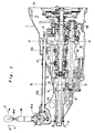
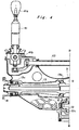
- FIGS. 1 , 2 , 3 and 4 show the construction of a countershaft transmission according to the present invention.
- FIGS. 2 , 3 and 4 are enlarged views of the respective three sections of the transmission divided by alternate long and short dash lines A-A and B-B in FIG. 1 .
- hatching is not rendered intentionally to make the structure of the transmission more easily understandable.
- a gearshift is disposed in a unified transmission case of first, second and third casings 1, 2 and 3, which are connected firmly consecutively from the side where an engine is placed.
- the first casing 1 includes a first partition wall 4, the second casing 2 includes a second partition wall 5, and the third casing 3 includes a cover wall 6 on the left side thereof, i.e., on the side opposite to the side where the engine is located.
- a main clutch CL is disposed in a clutch room 7 which is provided on the right side of the first partition wall 4, i.e., on the side toward the engine, and the right side end face 1a of the first casing 1 is connected to a casing which accommodates the engine.
- a flying wheel FW is provided in the clutch room 7 and is connected to the output shaft ES of the engine, and the above mentioned main clutch CL is mounted on the flying wheel FW.
- the left side end face 1b of the first casing 1 is fixed with the right side end face 2a of the second casing 2, and a first room 8 is defined by the first partition wall 4 of the first casing 1 and the second partition wall 5 of the second casing 2.
- a first room 8 is defined by the first partition wall 4 of the first casing 1 and the second partition wall 5 of the second casing 2.
- an input shaft (first shaft) 11 and a countershaft (second shaft) 12 are disposed parallel with each other, and a total of seven gear trains used for speed change are disposed between these two shafts.
- the right side of the input shaft 11 is supported rotatably by a bearing 11a, which is retained in the first partition wall 4, and the input shaft 11 extends further rightward through the first partition wall 4 into the clutch room 7 and the right end thereof is connected to the main clutch CL, which connects and disconnects the power transmission from the engine output shaft ES to the input shaft 11.
- the left side of the input shaft 11 is also supported rotatably by a bearing 11b, which is retained in the second partition wall 5.
- the right end of the countershaft 12 is supported rotatably by a bearing 12a, which is retained in the first partition wall 4.
- the left side of the countershaft 12 is supported rotatably by a bearing 12b, which is retained in the second partition wall 5, and the countershaft 12 extends further leftward through the second partition wall 5.
- a snap ring 15 is provided around the bearing 12a, and to place and remove this snap ring 15, an opening is provided on the lower side of the first casing 1, with a cap 16 covering the opening.
- the left side end face 2b of the second casing 2 is fixed with the right side end face 3a of the third casing 3, and a second room9 is defined by the second partition wall 5 and the cover wall 6.
- a gear train 28a and 28b is disposed, and the gears constituting this gear train are mounted on these shafts respectively and mesh with each other.
- the left end of the countershaft 12 is supported rotatably by a bearing 12c, which is retained in the cover wall 6.
- the right end of the output shaft 13 is supported rotatably by a bearing 13a, which is retained in the second partition wall 5.
- the central part and the left end of the output shaft 13 are supported also rotatably by bearings 13b and 13c, respectively, which are retained in the cover wall 6. More specifically, the left end of the output shaft 13 passes through the cover wall 6 and protrudes outward, and this protruding portion 14 is connected to a propeller shaft, which is then connected to drive wheels.
- the above mentioned seven speed change gear trains which are disposed parallel with one another between the input shaft 11 and the countershaft 12 in the first room 8, are a REVERSE gear train 27a, 27b and 27c, a LOW gear train 21a and 21b, a SECOND gear train 22a and 22b, a SIXTH gear train 26a and 26b, a FIFTH gear train 25a and 25b, a FOURTH gear train 24a and 24b, and a THIRD gear train 23a and 23b respectively from the right side in the axial direction.
- the LOW and SECOND gear trains comprise drive gears 21a and 22a, which are fixed on the input shaft 11, and driven gears 21b and 22b, which are mounted rotatably on the countershaft 12 and mesh with the drive gears 21a and 22a, respectively.
- synchro-mesh LOW and SECOND clutches 31 and 32 are provided, respectively. The engagement and disengagement of these clutches 31 and 32 are carried out by shifting a LOW or SECOND synchro-sleeve 47 in the axial direction.
- the REVERSE gear train comprises a drive gear 27a, which is fixed on the input shaft 11, an idle gear 27b, which is supported rotatably on the first partition wall 4 and meshes with the drive gear 27a, and a driven gear 27c, which is mounted rotatably on the countershaft 12 and meshes with the idle gear 27b.
- a synchro-mesh REVERSE clutch 37 is provided there, and the engagement and disengagement of the clutch 37 is carried out by shifting a REVERSE synchro-sleeve 48 in the axial direction.
- the THIRD, FOURTH, FIFTH and SIXTH gear trains comprise drive gears 23a, 24a, 25a and 26a, which are mounted rotatably on the input shaft 11, and driven gears 23b, 24b, 25b and 26b, which are fixed on the countershaft 12 and mesh with the drive gears 23a ⁇ 26a.
- synchro-mesh THIRD, FOURTH, FIFTH and SIXTH clutches 33, 34, 35 and 36 are provided, respectively.
- the engagement and disengagement of these clutches 33 ⁇ 36 are carried out by shifting a THIRD or FOURTH synchro-sleeve 45 or a FIFTH or SIXTH synchro-sleeve 46 in the axial direction.
- a gear change or a change of speed change ratio is carried out by selectively engaging one of the LOW, SECOND, THIRD, FOURTH, FIFTH, SIXTH and REVERSE clutches 31 ⁇ 37 to realize a power transmission through a corresponding speed change gear train.
- This gear change is performed by a driver who manipulates a shift lever 41, which is provided at the driver's seat.
- the mechanism to realize the shifting functions as follows.
- the shift lever 41 is supported by a spherical joint 41b, so that it can swing right and left and back and forth.
- the driver grips a shift knob 41b, which is provided at the upper end of the shift lever 41, and moves it back and fourth (in "Y" direction, which is the direction indicated by arrows Y in FIG. 1 ) or right and left (in the direction perpendicular to the paper carrying FIG. 1 , which direction is hereinafter designated as "X" direction).
- the movement of the shift lever 41 is conveyed to a main shift rod 42.
- the swing of the shift lever 41 in the X direction rotates the main shift rod 42 while the swing of the shift lever 41 in the Y direction transfers the main shift rod 42 in the axial direction (the right and left direction in the figure).
- a selector arm 43 is fixed on the other end of the main shift rod 42, and when the shift lever 41 is moved in the X direction, the front end of the selector arm 43 is led into the engaging groove of one of a plurality of shift pieces, which will be described below.
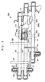
- FIG. 5 shows a mechanism 50 which includes these shift pieces and conveys the shifting force. Now, this shifting force conveying mechanism 50 is described with reference to FIG. 5 and FIG. 6.
- FIG. 6 is a view of the transmission without the second casing 2, being looked at toward the first casing 1, but it shows detent mechanisms 52, 54 and 56, which are provided in the second casing 2, to make the description more easily understandable.
- the shifting force conveying mechanism 50 is located at the upper part of the first room 8, and it comprises a LOW or SECOND shift rod 51, a THIRD or FOURTH shift fork shaft 53 and a FIFTH or SIXTH shift fork shaft 55.
- the right ends of these shift rod and fork shafts are supported by the first partition wall 4 while the left ends are supported by the second partition wall 5, respectively, and they are movable in the axial direction.
- the LOW or SECOND shift rod 51 is provided with a whirl-stop 51c and detent furrows 51a, which are used in cooperation with a detent mechanism 52 for setting one of the following three positions: specifically, LOW, NEUTRAL and SECOND.
- the THIRD or FOURTH shift fork shaft 53 and the FIFTH or SIXTH shift fork shaft 55 are provided with detent furrows 53a and 55a, respectively, which are used in cooperation with detent mechanisms 54 and 56, respectively, for setting one of the three positions: THIRD, NEUTRAL and FOURTH, and FIFTH, NEUTRAL and SIXTH, respectively.
- the LOW or SECOND shift rod 51, the THIRD or FOURTH shift fork shaft 53 and the FIFTH or SIXTH shift fork shaft 55, respectively, are provided with a LOW or SECOND shift piece 61, a THIRD or FOURTH shift piece 62 and a FIFTH or SIXTH shift piece 63, which are fixed thereon.
- a REVERSE shift piece 64 is provided movably in the axial direction on the THIRD or FOURTH shift fork shaft 53.
- These shift pieces 61 ⁇ 64 include selector grooves 61a ⁇ 64a, respectively, which are aligned laterally.
- the front end of the selector arm 43 is designed to engage one of the selector grooves 61a ⁇ 64a.
- the shift lever 41 By moving the shift lever 41 in the X direction, the front end of the selector arm 43 is selectively engaged to one of the selector grooves 61a ⁇ 64a, and by moving the shift lever 41 in the Y direction, the shift piece which has the selector groove engaged to the selector arm 43 is transferred in the axial direction.
- the THIRD or FOURTH shift fork shaft 53 and the FIFTH or SIXTH shift fork shaft 55 are provided with a THIRD or FOURTH shift fork 57 and a FIFTH or SIXTH shift fork 58, respectively.
- the THIRD or FOURTH shift fork 57 is fixed on the THIRD or FOURTH shift fork shaft 53 and is axially slidable on the FIFTH or SIXTH shift fork shaft 55.
- the FIFTH or SIXTH shift fork 58 is fixed on the FIFTH or SIXTH shift fork shaft 55 and is axially slidable on the THIRD or FOURTH shift fork shaft 53.
- the THIRD or FOURTH shift fork 57 engages the THIRD or FOURTH synchro-sleeve 45, which activates the THIRD clutch 33 and the FOURTH clutch 34, while the FIFTH or SIXTH shift fork 58 engages the FIFTH or SIXTH synchro-sleeve 46, which activates the FIFTH clutch 35 and the SIXTH clutch 36.
- the selector arm 43 is engaged, for example, to the selector groove 62a or 63a of the THIRD or FOURTH shift piece 62 or the FIFTH or SIXTH shift piece 63, and then the THIRD or FOURTH shift fork shaft 53 or the FIFTH or SIXTH shift fork shaft 55 is transferred appropriately in the axial direction to selectively activate one of the THIRD ⁇ SIXTH clutches 33 ⁇ 36.
- the LOW or SECOND synchro-sleeve 47 which activates the LOW and SECOND clutches 31 and 32, and the REVERSE synchro-sleeve 48, which activates the REVERSE clutch 37, are located on the countershaft 12 at the lower part of the transmission. Therefore, a LOW or SECOND shift fork 73 and a REVERSE shift fork 76, which engage these synchro-sleeves 47 and 48, are mounted, respectively, on a LOW or SECOND shift fork shaft 71 and a REVERSE shift fork shaft 75, which are provided movably in the axial direction at the lower part of the transmission.
- the LOW or SECOND shift fork 73 is fixed on the LOW or SECOND shift fork shaft 71 and is axially slidable on the REVERSE shift fork shaft 75 while the REVERSE shift fork 76 is fixed on the REVERSE shift fork shaft 75 and is axially slidable on the LOW or SECOND shift fork shaft 71.
- a LOW or SECOND rocking lever 65 and a REVERSE rocking lever 66 are provided laterally in the first room 8 as detailed in FIGS. 6 , 7 and 8 .
- rocking levers 65 and 66 are long plate-like members and positioned close to each other and are supported by a pair of retaining ribs 4a and 4b, which protrude from the first partition wall 4 into the first room 8. More specifically, an aperture is provided extending from the outer surface of the first casing 1 and passing through the retaining ribs 4a and 4b, and a retaining pin 67 is inserted from the outside of the casing into this aperture to support the rocking levers 65 and 66 at the center thereof as shown in FIG. 6 . In this condition, each rocking lever is independently pivotable around the retaining pin 67. Because of this arrangement, the rocking levers 65 and 66 are easily mountable. They are placed between the retaining ribs 4a and 4b and then pinned with the retaining pin 67, which is inserted from the outside.
- the upper end 65a of the LOW or SECOND rocking lever 65 is set in a recess 51b which is provided on the LOW or SECOND shift rod 51 while the lower end 65b is set in an engaging groove 72a which is provided on an engaging member 72 fixed on the LOW or SECOND shift fork shaft 71.
- the LOW or SECOND shift rod 51 is transferred in the axial direction by manipulating the shift lever 41
- the LOW or SECOND shift fork shaft 71 is transferred in the opposite axial direction by the movement of the LOW or SECOND rocking lever 65, which movement is caused by the movement of the LOW or SECOND shift rod 51.
- the LOW or SECOND synchro-sleeve 47 is shifted in the axial direction correspondingly by the LOW or SECOND shift fork 73, which is fixed on the LOW or SECOND shift fork shaft 71.
- the LOW or SECOND clutch 31 or 32 can be activated selectively.
- the upper end 66a of the REVERSE rocking lever 66 is set in an engaging groove 64b which is provided in the REVERSE shift piece 64 while the lower end 66b is set in a recess 75a which is provided on the REVERSE shift fork shaft 75.
- the REVERSE shift piece 64 is transferred in the axial direction on the THIRD or FOURTH shift fork shaft 53
- the REVERSE shift fork shaft 75 is transferred in the opposite axial direction by the movement of the REVERSE rocking lever 66, which is caused by the transfer of the REVERSE shift piece 64.
- the REVERSE synchro-sleeve 48 is shifted in the axial direction correspondingly by the REVERSE shift fork 76, which is fixed on the REVERSE shift fork shaft 75, to activate the REVERSE clutch 37.
- the process of assembling the countershaft transmission is described.
- the first casing 1 is placed with the end face 1a which meet the casing of the engine, facing downward, and with the first room 8 opening upward.
- the input shaft 11 and the countershaft 12 with the speed change gear trains, clutches, etc. subassembled, respectively are oriented vertically and put into the first room 8 from above, and these shafts are mounted in the first partition wall 4, with the bearings 11a and 12a which support the shafts rotatably.
- the second casing 2 is mounted on the first casing 1 to enclose the input shaft 11 and the countershaft 12, which are protruding upward from the first casing 1.
- the left ends and the middle portions of these shafts 11 and 12 shown in FIG. 1 are supported rotatably with bearings 11b and 12b in the second partition wall 5, and the input shaft 11 and the countershaft 12 are rotatable in the first room 8.
- the above countershaft transmission is assembled first by setting the first casing 1 with its end face 1a which meets the casing of the engine, facing downward, and then by mounting the second casing 2 and the third casing 3 in this order as described above.
- the input shaft 11, the countershaft 12 and the output shaft 13 are maintained in the respective casings, standing upward. Therefore, there is no need of jigs, which otherwise be needed to retain these shafts in the assembly, so the assembly operation is carried out simply and easily.
- the invention comprises thus a transmission case with first, second and third casings 1, 2 and 3, which are connected side by side in this order from an engine.
- An input shaft 11 and a countershaft 12 with speed change gear trains and clutches are disposed in a first room 8 which is defined by the first and second casings, and the both ends of these shafts 11 and 12 are supported rotatably in partition walls 4 and 5 which are provided with the first and second casings, respectively.
- the side of the countershaft 12 which is located away from the engine extends into a second room 9 defined by the second and third casings, in which room, an output shaft 13 is disposed.
- a constant mesh type gear train is disposed in the second room 9 for power transmission between the countershaft 12 and the output shaft 13. Furthermore, the end of the output shaft 13 which is located toward the engine is supported rotatably by the second casing while the end of the countershaft 12 and the side of the output shaft 13 which are located away from the engine are supported rotatably by the third casing.
Landscapes
- Engineering & Computer Science (AREA)
- General Engineering & Computer Science (AREA)
- Mechanical Engineering (AREA)
- Structure Of Transmissions (AREA)
- General Details Of Gearings (AREA)
Claims (5)
- Gegenwellengetriebe, in dessen Getriebegehäuse (1, 2, 3) eine erste Welle (11), die mit einem Motor verbunden ist, eine zweite Welle (12), die sich parallel zu der ersten Welle (11) erstreckt, eine dritte Welle (13), die sich in Richtung von dem Motor weg gegen die erste Welle (11) erstreckt, sowie eine Mehrzahl von Gangwechselzahnradzügen (21a - 27a, 21b, - 27b), die zwischen der ersten Welle (11) und der zweiten Welle (12) angeordnet sind, drehbar aufgenommen sind, worin:das Getriebegehäuse (1, 2, 3) ein erstes Gehäuse (1), ein zweites Gehäuse (2) und ein drittes Gehäuse (3) aufweist, die in dieser Reihenfolge von einer Seite her, wo der Motor angeordnet ist, verbunden sind;wobei die erste Welle (11), die zweite Welle (12) und die Gangwechselzahnradzüge (21a - 27a, 21b - 27b) in einem ersten Raum (8) angeordnet sind, der durch die ersten und zweiten Gehäuse (1, 2) definiert ist;
wobei Seiten der ersten und zweiten Wellen (11, 12), die zu dem Motor hin angeordnet sind, an dem ersten Gehäuse (1) drehbar gelagert sind, wohingegen eine Seite der ersten Welle (11), die von dem Motor weg angeordnet ist, an dem zweiten Gehäuse (2) drehbar gelagert ist;
wobei eine Seite der zweiten Welle (12), die von dem Motor weg angeordnet ist, die dritte Welle (13) und ein Übertragungsmittel (28a, 28b), das die Kraftübertragung zwischen der zweiten und der dritten Welle (12, 13) ausführt, in einem zweiten Raum (9) angeordnet sind, der durch die zweiten und dritten Gehäuse (2, 3) definiert ist;
wobei eine Seite der dritten Welle (13), die zum Motor hin angeordnet ist, an dem zweiten Gehäuse (2) drehbar gelagert ist, während Seiten der zweiten und der dritten Welle (12, 13), die von dem Motor weg angeordnet sind, an dem dritten Gehäuse (3) drehbar gelagert sind;
wobei das erste Gehäuse (1) eine erste Trennwand (4) enthält, wobei die erste Trennwand (4) die Seiten der ersten und zweiten Wellen (11, 12), die zu dem Motor hinweisend angeordnet sind, drehbar lagern;
wobei das zweite Gehäuse (2) eine zweite Trennwand (5) enthält, wobei die zweite Trennwand (5) die Seite der dritten Welle (13), die zu dem Motor hinweisend angeordnet ist, durch ein Lager (13a) drehbar lagert, das in der zweiten Trennwand (5) gehalten wird, und die zweite Trennwand (5) auch einen mittleren Abschnitt der zweiten Welle (12) drehbar lagert, der sich durch die zweite Trennwand (5) hindurch erstreckt; und
wobei das dritte Gehäuse (3) eine Deckwand (6) enthält, wobei die Deckwand (6) die Seiten der zweiten und der dritten Welle (12, 13), die von dem Motor weg angeordnet sind, drehbar lagert;
dadurch gekennzeichnet, dass die zweite Trennwand (5) die Seite der ersten Welle (11), die von dem Motor weg angeordnet ist, durch ein weiteres Lager (11 b) drehbar lagert, das in der zweiten Trennwand (5) gehalten wird, wodurch die Seiten der ersten und der dritten Welle (11, 13) aufeinander zuweisen. - Gegenwellengetriebe nach Anspruch 1, worin die dritte Welle (13) axial in der gleichen Richtung wie die erste Welle (11) in dem Getriebegehäuse (1, 2, 3) angeordnet ist.
- Gegenwellengetriebe nach Anspruch 1, das ferner eine Hauptkupplung (CL) aufweist, die in einem Kupplungsraum (7) angeordnet ist, der durch das erste Gehäuse (1), das die erste Trennwand (4) enthält, und den Motor, der mit einem Seitenende des ersten Gehäuses (1) verbunden ist, definiert ist, worin:sich die Seite der ersten Welle (11) durch die erste Trennwand (4) hindurchgeht und sich in den Kupplungsraum (7) erstreckt, unddie erste Welle (11) durch die Hauptkupplung (CL) mit einer Ausgangswelle (ES) des Motors drehend verbunden ist.
- Gegenwellengetriebe nach Anspruch 1, welches zusammengebaut ist durch:Stellen des ersten Gehäuses (1) derart, dass ein Seitenende, das sich mit dem Motor trifft, nach unten weist, wobei sich der erste Raum (8) nach oben öffnet,vertikales Einsetzen der ersten und der zweiten Welle (11, 12), die jeweils mit den Gangwechselzahnrädern (21a - 27a, 21b - 27b) und den Kupplungen vormontiert sind, von oben in den ersten Raum (8),vertikales und drehbares Lagern der ersten und der zweiten Welle (11, 12) an dem ersten Gehäuse (1); undIneingriffbringen eines Antriebszahnrads (21a - 27a) mit einem Abtriebszahnrad (21b - 27b) für jeden Gangwechselzahnradzug.
- Gegenwellengetriebe nach Anspruch 4, welches ferner zusammengebaut ist durch:Montieren des zweiten Gehäuses (2) an dem ersten Gehäuse (1) derart, dass das zweite Gehäuse (2) die erste und die zweite Welle (11, 12), die von dem ersten Gehäuse (1) nach oben vorstehen, wie in Anspruch 5 erwähnt, umschließt,drehbares Lagern der Seite der ersten Welle (11), die von dem Motor weg angeordnet ist, und eines mittleren Abschnitts der zweiten Welle (12) an dem zweiten Gehäuse (2);Montieren eines Antriebszahnrads (28a), das das Übertragungsmittel (28a, 28b) darstellt, auf der zweiten Welle (12), die durch das zweite Gehäuse (2) nach oben vorsteht,Montieren und vertikales und drehbares Lagern der dritten Welle (13), die mit einem Abtriebszahnrad (28b) vormontiert ist, das das Übertragungsmittel (28a, 28b) darstellt, in dem zweiten Gehäuse (2),
wobei die Seite der dritten Welle (13), die zu dem Motor hin angeordnet ist, nach unten weist, undMontieren des dritten Gehäuses (3) an dem zweiten Gehäuse (2) derart, dass das dritte Gehäuse (3) die zweite und die dritte Welle (11, 12), die von dem zweiten Gehäuse (2) nach oben vorstehen, abdeckt.
Applications Claiming Priority (2)
| Application Number | Priority Date | Filing Date | Title |
|---|---|---|---|
| JP4284199 | 1999-02-22 | ||
| JP11042841A JP3131194B2 (ja) | 1999-02-22 | 1999-02-22 | カウンターシャフト式変速機 |
Publications (3)
| Publication Number | Publication Date |
|---|---|
| EP1031765A2 EP1031765A2 (de) | 2000-08-30 |
| EP1031765A3 EP1031765A3 (de) | 2005-11-23 |
| EP1031765B1 true EP1031765B1 (de) | 2008-11-26 |
Family
ID=12647228
Family Applications (1)
| Application Number | Title | Priority Date | Filing Date |
|---|---|---|---|
| EP00101595A Expired - Lifetime EP1031765B1 (de) | 1999-02-22 | 2000-01-27 | Nebenwellengetriebe |
Country Status (5)
| Country | Link |
|---|---|
| US (1) | US6279423B1 (de) |
| EP (1) | EP1031765B1 (de) |
| JP (1) | JP3131194B2 (de) |
| CA (1) | CA2299028C (de) |
| DE (1) | DE60040882D1 (de) |
Cited By (1)
| Publication number | Priority date | Publication date | Assignee | Title |
|---|---|---|---|---|
| CN105003631A (zh) * | 2015-06-30 | 2015-10-28 | 浙江长泰机械有限公司 | 汽车变速器 |
Families Citing this family (7)
| Publication number | Priority date | Publication date | Assignee | Title |
|---|---|---|---|---|
| US20050223833A1 (en) * | 2004-03-31 | 2005-10-13 | Herzog Contracting Corp. | Transmission with top mounted shift mechanism |
| DE102005005338B3 (de) * | 2005-01-27 | 2006-08-10 | Getrag Getriebe- Und Zahnradfabrik Hermann Hagenmeyer Gmbh & Cie Kg | Stufenwechselgetriebe |
| TWI265107B (en) * | 2005-03-25 | 2006-11-01 | Sanyang Industry Co Ltd | Power-transferring mechanism |
| DE102006061515B4 (de) | 2006-12-18 | 2010-12-30 | Getrag Getriebe- Und Zahnradfabrik Hermann Hagenmeyer Gmbh & Cie Kg | Doppelkupplungsgetriebe |
| JP5146253B2 (ja) * | 2008-10-23 | 2013-02-20 | トヨタ自動車株式会社 | 手動変速機 |
| JP4935804B2 (ja) | 2008-12-18 | 2012-05-23 | トヨタ自動車株式会社 | インプットシャフトの支持構造 |
| US11713808B1 (en) * | 2022-03-08 | 2023-08-01 | Dana Heavy Vehicle Systems Group, Llc | Systems for transmission |
Family Cites Families (7)
| Publication number | Priority date | Publication date | Assignee | Title |
|---|---|---|---|---|
| JPS5733264A (en) | 1980-08-01 | 1982-02-23 | Iseki & Co Ltd | Input shaft bearing retainer in transmission mechanism |
| US5052238A (en) * | 1990-04-17 | 1991-10-01 | Borg-Warner Automotive, Inc. | Manual transmission shift linkage |
| JPH06221432A (ja) | 1993-01-27 | 1994-08-09 | Mazda Motor Corp | 変速機の変速操作機構 |
| JP3697790B2 (ja) * | 1996-03-29 | 2005-09-21 | マツダ株式会社 | 歯車式変速機構造 |
| JPH10103429A (ja) * | 1996-09-30 | 1998-04-21 | Mazda Motor Corp | 歯車式変速機構造 |
| JPH10103428A (ja) * | 1996-09-30 | 1998-04-21 | Mazda Motor Corp | 歯車式変速機構造 |
| JPH1142841A (ja) | 1997-07-25 | 1999-02-16 | Toshiba Corp | インクリボンカセット |
-
1999
- 1999-02-22 JP JP11042841A patent/JP3131194B2/ja not_active Expired - Fee Related
-
2000
- 2000-01-27 EP EP00101595A patent/EP1031765B1/de not_active Expired - Lifetime
- 2000-01-27 DE DE60040882T patent/DE60040882D1/de not_active Expired - Fee Related
- 2000-02-21 CA CA002299028A patent/CA2299028C/en not_active Expired - Fee Related
- 2000-02-22 US US09/507,791 patent/US6279423B1/en not_active Expired - Fee Related
Cited By (2)
| Publication number | Priority date | Publication date | Assignee | Title |
|---|---|---|---|---|
| CN105003631A (zh) * | 2015-06-30 | 2015-10-28 | 浙江长泰机械有限公司 | 汽车变速器 |
| CN105003631B (zh) * | 2015-06-30 | 2018-03-23 | 浙江长泰机械有限公司 | 汽车变速器 |
Also Published As
| Publication number | Publication date |
|---|---|
| JP3131194B2 (ja) | 2001-01-31 |
| EP1031765A2 (de) | 2000-08-30 |
| JP2000240737A (ja) | 2000-09-05 |
| CA2299028A1 (en) | 2000-08-22 |
| US6279423B1 (en) | 2001-08-28 |
| CA2299028C (en) | 2006-04-11 |
| EP1031765A3 (de) | 2005-11-23 |
| DE60040882D1 (de) | 2009-01-08 |
Similar Documents
| Publication | Publication Date | Title |
|---|---|---|
| US7360466B2 (en) | Double clutch transmission | |
| EP2003369B1 (de) | Getriebe | |
| KR100300294B1 (ko) | 헬리컬기어복합변속기 | |
| EP0821182B1 (de) | Kompaktes Handschaltgetriebe für Kraftfahrzeuge | |
| EP2273153A2 (de) | Mehrstufiges Doppelkupplungsgetriebe für Kraftfahrzeug | |
| US5031473A (en) | Automotive transmission | |
| EP0107060A2 (de) | Rückwärtsgangeinrichtung mit Kettentrieb für handbetätigte Getriebe | |
| EP1031765B1 (de) | Nebenwellengetriebe | |
| US5309782A (en) | Multiple ratio manual transmission | |
| US6067870A (en) | Manual transaxle | |
| JPH04224366A (ja) | 手動変速機 | |
| EP0821183B1 (de) | Kompaktes Handschaltgetriebe | |
| EP1031772B1 (de) | Gangschalteinrichtung mit Schwenkhebeln | |
| KR20060055467A (ko) | 전면 횡 방향 드라이브를 갖는 차량용 수동 변속기 | |
| JPH10205618A (ja) | 歯車式変速機構造及びその組立方法 | |
| EP0206563A2 (de) | Mehrgängiges Gerriebe mit einer Zwischenwelle | |
| WO2014210128A1 (en) | Compact manual transaxle with two speed differential | |
| JPH04302749A (ja) | 変速機 | |
| JPH07269659A (ja) | 変速機 | |
| JPH07317896A (ja) | 変速機の操作機構 | |
| JPH0535289B2 (de) | ||
| JPH05321991A (ja) | トランスミッションの変速ギヤ配列構造 | |
| EP0314382A2 (de) | Sechsganghandschaltgetriebe | |
| JPH02134439A (ja) | 歯車変速機 | |
| JPH0389056A (ja) | 自動車用変速機 |
Legal Events
| Date | Code | Title | Description |
|---|---|---|---|
| PUAI | Public reference made under article 153(3) epc to a published international application that has entered the european phase |
Free format text: ORIGINAL CODE: 0009012 |
|
| AK | Designated contracting states |
Kind code of ref document: A2 Designated state(s): AT BE CH CY DE DK ES FI FR GB GR IE IT LI LU MC NL PT SE |
|
| AX | Request for extension of the european patent |
Free format text: AL;LT;LV;MK;RO;SI |
|
| PUAL | Search report despatched |
Free format text: ORIGINAL CODE: 0009013 |
|
| AK | Designated contracting states |
Kind code of ref document: A3 Designated state(s): AT BE CH CY DE DK ES FI FR GB GR IE IT LI LU MC NL PT SE |
|
| AX | Request for extension of the european patent |
Extension state: AL LT LV MK RO SI |
|
| 17P | Request for examination filed |
Effective date: 20051230 |
|
| AKX | Designation fees paid |
Designated state(s): DE GB |
|
| GRAP | Despatch of communication of intention to grant a patent |
Free format text: ORIGINAL CODE: EPIDOSNIGR1 |
|
| GRAS | Grant fee paid |
Free format text: ORIGINAL CODE: EPIDOSNIGR3 |
|
| GRAA | (expected) grant |
Free format text: ORIGINAL CODE: 0009210 |
|
| AK | Designated contracting states |
Kind code of ref document: B1 Designated state(s): DE GB |
|
| REG | Reference to a national code |
Ref country code: GB Ref legal event code: FG4D |
|
| REF | Corresponds to: |
Ref document number: 60040882 Country of ref document: DE Date of ref document: 20090108 Kind code of ref document: P |
|
| PGFP | Annual fee paid to national office [announced via postgrant information from national office to epo] |
Ref country code: DE Payment date: 20090123 Year of fee payment: 10 |
|
| PGFP | Annual fee paid to national office [announced via postgrant information from national office to epo] |
Ref country code: GB Payment date: 20090121 Year of fee payment: 10 |
|
| PLBE | No opposition filed within time limit |
Free format text: ORIGINAL CODE: 0009261 |
|
| STAA | Information on the status of an ep patent application or granted ep patent |
Free format text: STATUS: NO OPPOSITION FILED WITHIN TIME LIMIT |
|
| 26N | No opposition filed |
Effective date: 20090827 |
|
| GBPC | Gb: european patent ceased through non-payment of renewal fee |
Effective date: 20100127 |
|
| PG25 | Lapsed in a contracting state [announced via postgrant information from national office to epo] |
Ref country code: DE Free format text: LAPSE BECAUSE OF NON-PAYMENT OF DUE FEES Effective date: 20100803 |
|
| PG25 | Lapsed in a contracting state [announced via postgrant information from national office to epo] |
Ref country code: GB Free format text: LAPSE BECAUSE OF NON-PAYMENT OF DUE FEES Effective date: 20100127 |