EP1031383A2 - Rad-Auftragsvorrichtung - Google Patents
Rad-Auftragsvorrichtung Download PDFInfo
- Publication number
- EP1031383A2 EP1031383A2 EP00102528A EP00102528A EP1031383A2 EP 1031383 A2 EP1031383 A2 EP 1031383A2 EP 00102528 A EP00102528 A EP 00102528A EP 00102528 A EP00102528 A EP 00102528A EP 1031383 A2 EP1031383 A2 EP 1031383A2
- Authority
- EP
- European Patent Office
- Prior art keywords
- application
- application roller
- roller
- sealing
- doctor
- Prior art date
- Legal status (The legal status is an assumption and is not a legal conclusion. Google has not performed a legal analysis and makes no representation as to the accuracy of the status listed.)
- Withdrawn
Links
- 239000011248 coating agent Substances 0.000 title claims description 11
- 238000000576 coating method Methods 0.000 title claims description 11
- 238000007789 sealing Methods 0.000 claims abstract description 57
- 239000012530 fluid Substances 0.000 claims abstract description 27
- 239000000758 substrate Substances 0.000 claims description 34
- 239000000463 material Substances 0.000 claims description 18
- 238000004519 manufacturing process Methods 0.000 claims description 12
- 230000002093 peripheral effect Effects 0.000 claims description 12
- 238000005553 drilling Methods 0.000 claims description 11
- 230000035515 penetration Effects 0.000 claims description 10
- 229920001343 polytetrafluoroethylene Polymers 0.000 claims description 4
- 239000004810 polytetrafluoroethylene Substances 0.000 claims description 4
- -1 polytetrafluoroethylene Polymers 0.000 claims description 2
- 239000000853 adhesive Substances 0.000 description 33
- 230000001070 adhesive effect Effects 0.000 description 32
- 239000003292 glue Substances 0.000 description 11
- 239000007788 liquid Substances 0.000 description 6
- 230000000149 penetrating effect Effects 0.000 description 3
- 230000000694 effects Effects 0.000 description 2
- 238000003754 machining Methods 0.000 description 2
- 239000002184 metal Substances 0.000 description 2
- 238000000034 method Methods 0.000 description 2
- 238000003801 milling Methods 0.000 description 2
- 238000005240 physical vapour deposition Methods 0.000 description 2
- 239000004831 Hot glue Substances 0.000 description 1
- 229920000271 Kevlar® Polymers 0.000 description 1
- 238000005299 abrasion Methods 0.000 description 1
- 238000010521 absorption reaction Methods 0.000 description 1
- 239000002253 acid Substances 0.000 description 1
- 150000007513 acids Chemical class 0.000 description 1
- 230000004888 barrier function Effects 0.000 description 1
- 230000015572 biosynthetic process Effects 0.000 description 1
- 239000013013 elastic material Substances 0.000 description 1
- 238000010891 electric arc Methods 0.000 description 1
- 238000005530 etching Methods 0.000 description 1
- 239000004761 kevlar Substances 0.000 description 1
- 239000007769 metal material Substances 0.000 description 1
- 229920001296 polysiloxane Polymers 0.000 description 1
- 230000000717 retained effect Effects 0.000 description 1
- 239000007787 solid Substances 0.000 description 1
- 238000004544 sputter deposition Methods 0.000 description 1
- 239000007858 starting material Substances 0.000 description 1
- 239000000126 substance Substances 0.000 description 1
Images



Classifications
-
- B—PERFORMING OPERATIONS; TRANSPORTING
- B42—BOOKBINDING; ALBUMS; FILES; SPECIAL PRINTED MATTER
- B42C—BOOKBINDING
- B42C11/00—Casing-in
- B42C11/04—Machines or equipment for casing-in or applying covers to books
-
- B—PERFORMING OPERATIONS; TRANSPORTING
- B42—BOOKBINDING; ALBUMS; FILES; SPECIAL PRINTED MATTER
- B42C—BOOKBINDING
- B42C9/00—Applying glue or adhesive peculiar to bookbinding
- B42C9/0006—Applying glue or adhesive peculiar to bookbinding by applying adhesive to a stack of sheets
Definitions
- the present invention relates to a wheel application device for applying a Fluids on a substrate, with an applicator roller rotatably mounted on a housing, whose peripheral surface can be acted upon by a fluid and on which Substrate can be moved so that fluid from the surface of the Application roller is transferred to the substrate with one with the application roller cooperating doctor device with a doctor element that is so relative to the Surface of the applicator roller is arranged on the rotating applicator roller located fluid is partially stripped, and with at least one in lateral end region of the application roller arranged sealing device for lateral sealing between the doctor element and / or the application roller and the housing of the application device, the sealing device being one with the Application roller and / or the doctor element in contact, by means of a Has pressure element clampable contact element.
- Such wheel applicators are used to apply liquid adhesives or apply other fluids to surfaces of substrates.
- the application roller In a known wheel application device, which from the company Nordson Engineering GmbH, Lilienthalstr. 6, Lueneburg, Germany, under the type designation RA 80 is offered, the application roller with a lower section partly into a liquid-adhesive one that is delimited by the housing Glue pool immersed.
- the application roller protrudes with an upper section out of the housing and is with its circumferential surface with a relative to the Applicable roller movable substrate, such as a book spine in contact. As the applicator roller rotates, it becomes more fluid on the surface of the Adhesive roller adhesive adhesive transported to the surface of the substrate.
- the distance from the application roller is variable.
- the application roller points in the area of its peripheral surface Depressions or recesses or a structured surface.
- glue penetrates into the recesses in the case Applicator roller.
- the doctor element in contact stands with the surface of the application roller, adhesive is stripped so that only the adhesive contained in the recesses adhere to the application roller remains.
- the recesses at least partially, so that the adhesive from the out takes on the substrate. Leave with the help of such application rollers relatively small amounts of adhesive transfer to the substrate, like this may be necessary in the manufacture of hygiene articles.
- the in the lateral end area of the application roller and in the lateral end area of the Doctor element of the doctor device arranged sealing device has a the contact element on the side end face of the application roller on which is used for a lateral seal between the application roller and the Housing of the application device and a lateral seal between the Squeegee element and the application roller is used.
- a sealing device is especially in the case of application devices for applying relatively small amounts of Liquids and to apply liquids as evenly as possible Substrates provided.
- the sealing device causes a stripping of Adhesive from the side face of the application roller by means of the contact element, so that adhesive adheres to the side face of the Application roller can be prevented and even application of adhesive even in the lateral end region of the application roller can be guaranteed.
- Another disadvantage of the known application device is that the Adhesive adhering to the roller particularly in the area of the recesses is only partially transferred to the substrate and only an incomplete one Emptying of the recesses is achieved. This is due to the geometric structure attributed to the surface of the application roller.
- Structured surfaces by so-called Molettieren so that recesses for Adhesive absorption occurs. Knurled tools are used for mettling used.
- a surface structure is produced by etching.
- the applicator roller is eroded using an electric arc structured, but also the surface structure of the Application roller and the order result can be improved.
- Another disadvantage of the known application device results from the type and Way of producing the housing, which is made of a solid block of metal is produced by machining such as milling. For example to form the glue pool in the metallic block, large parts of the Blocks are milled out, so that a high material consumption for manufacturing of the housing arises. For this reason, the material and manufacturing costs relatively high.
- the object of the present invention is a wheel application device to provide a fluid to a substrate, which have the disadvantages avoids the prior art and even application even less Fluid quantities on substrates over the entire application range enabled and on simple, inexpensive way to produce.
- the invention solves this problem with a wheel application device at the beginning mentioned type in that an elastically deformable sealing element between the pressure piece and the contact element is arranged.
- the elastically deformable sealing element according to the invention improves the Sealing effect in the lateral end area of the application roller significantly, what Attempts have been confirmed.
- the elastic sealing element is by means of Pressure piece pressed and thereby on the one hand to the contact element and adjacent portions of the housing pressed so that penetration of Liquid from the interior of the housing and thus leaks reliably be prevented.
- the elastic sealing element may be used pressed against a portion of the doctor device, so that a seal between the housing and doctor blade device - in the upper region of the housing - achieved becomes.
- that arranged between the pressure piece and the contact element ensures elastic sealing element for a certain dynamic balancing process in the case of local increases in the surface pressure between the contact element and Applicator roller, which are compensated in an advantageous manner.
- the invention also achieves the object in an application device described at the outset characterized in that the contact element of the sealing device from a elastically deformable material is formed or one of an elastically deformable Has material formed penetration element, so that the doctor element Doctor device can penetrate into the contact element or the penetrating element.
- the sealing device is formed from an elastic material or an elastic penetration element is inserted or in the contact element this is arranged, the lateral end portion of the doctor element partially penetrates in the elastic contact element or the penetrating element, whereby in Edge area of the applicator roller reaches a complete and clean wiping becomes. If necessary, the squeegee element projects somewhat laterally over the application roller addition, so that a complete stripping at the very edge of the Applicator roller is realized and a clean wiping in this edge area so that a particularly even application of adhesive is ultimately achieved.
- a wheel application device for applying a fluid to a substrate an application roller rotatably mounted on a housing, the peripheral surface thereof can be acted upon with a fluid and the substrate can be moved past, that fluid is transferred from the surface of the application roller to the substrate, the object is achieved in that the applicator roller on its peripheral region a variety of recesses made by drilling and a coating having.
- the recesses made by high-precision drilling enable that Production of a precise, even surface structure with a geometric exact recesses, the optimal filling with fluid and a largely complete emptying of the recesses during the application of the fluid enable the substrate.
- the one consisting of a metallic hard material The coating also supports a largely complete emptying of the Recesses during the fluid application and prevents unwanted to strong adherence of the fluid to the surface of the application roller.
- the invention Combination of the recesses made by drilling and the Coating leads to more uniform coating than known application devices Orders even with small order quantities per unit area.
- the invention further solves the problem with an application device of the preceding described type in that the housing has a separate base plate and has several separate side plates, which are used to manufacture the housing are attachable to each other.
- the housing is assembled from separate side plates and a base plate, are the material losses in the manufacture of the housing compared to known manufacturing methods significantly reduced, since no longer from one full block of material parts must be milled out. Instead, the Base plates and the side plates made of plate-shaped starting materials manufactured by using only small amounts of material by machining processes how milling is removed from the starting plates, for example Recordings for bearings or holes to attach the base plate and To produce side plates together.
- the housing is made of separate panels assembled, there is the further advantage that in the event that the base plate or one of the separate side plates is damaged, for example by wear can be easily replaced without the entire housing should be exchanged.
- a preferred embodiment of the invention is characterized in that the elastic sealing element has a recess into which a sealing cord insertable for sealing between the housing and the doctor device is. In this way, one can regularly cover the entire width of the Application device extending sealing cord clamped laterally and into the side sealing device are integrated so that they by means of Pressure piece is pressed.
- the contact element which is in contact with the application roller is preferably present the sealing device from a wear-resistant and temperature resistant material such as hard paper (Pertinax) to be in continuous use for to be able to provide a reliable seal.
- a wear-resistant and temperature resistant material such as hard paper (Pertinax) to be in continuous use for to be able to provide a reliable seal.
- the pressure piece Sealing device can be clamped by means of two clamping screws, which are extend through bores formed in a side wall as in this way a permanent and even bracing is possible with simple means.
- the recesses formed on the peripheral region of the application roller each have a dome-shaped surface.
- a dome-shaped Surface in the area of the recesses as tests have confirmed, on the one hand for a good filling and emptying of the recesses and on the other hand for easy manufacture with appropriately shaped Drilling tools.
- Each recess preferably has about one Diameter of 0.69 millimeters, a depth of 0.14 millimeters and the spherical surface has a radius of about 1 millimeter.
- a plurality of Recesses are arranged in parallel rows and in the direction of rotation Applicator roller are arranged offset from each other.
- the have on the peripheral region of the Applicator roller formed recesses each have an asymmetrical surface shape on, which results from the fact that during drilling the longitudinal axis of the drill is arranged obliquely to the surface of the application roller.
- the base plate and the side plates have essentially one rectangular shape and are attached to each other by screw connection.
- two opposite side plates each have one Recess for receiving a lateral sealing device.
- a wheel application device according to the invention 2 is used to apply liquid adhesive to parts of Hygiene items such as diapers, but can also be surfaces of other substrates be provided with any fluids.
- the application device 2 has an existing one made of a metallic material Housing 4, which from a base plate 6 and screwed to the base plate 6 Side plates 8, 10, 12, 14 are formed, which by screw connections are releasably attached to each other and which are essentially rectangular Have shapes.
- Side plates 8, 10, 12, 14 are formed, which by screw connections are releasably attached to each other and which are essentially rectangular Have shapes.
- a plurality of partially Threads formed bores 16 (not all of which are shown in the figures Are provided, into or through which dowel pins or threaded bolts are insertable.
- Glue pool 18 formed, which in a manner not explained with a liquid adhesive such as hot melt adhesive can be filled.
- an axis of rotation 22 adhesive is transported out of the glue pool 18.
- the application roller 20 projects with a - relatively small - upper section out of the interior of the housing 4 (see FIG. 3), so that the substrate, which is to be provided with adhesive in contact with the outer peripheral surface the application roller 20 and / or with on the outer peripheral surface adhesive can be brought while the substrate is relative to the Applicator roller 20 - preferably - is translationally moved past.
- glue from the glue pool 18 by means of the application roller 20 on the Transfer substrate is glue from the glue pool 18 by means of the application roller 20 on the Transfer substrate.
- Recesses or other surface structures can be formed, as below 9 to 16 is explained in more detail so that adhesive in the area of Glue pool 18 penetrates into the recesses or surface structure and emerges during contact with the substrate and on the substrate attached.
- FIG. 4 shows a doctor device 24 which interacts with the application roller 20 shown in the region of a recess 26 formed on the housing 4 (see Fig. 3) is arranged.
- a laterally over the length of the application roller 20 extending metal base body 28 carries a doctor element 30 in shape a resilient sheet, which with the help of a clamping body 32 and a plurality of threaded screws 34 formed in the base body 28 Threaded holes are screwed, is releasably attached to the base body 28.
- the doctor element 30 is thus relative to the surface of the application roller 20 positions that adhesive on the rotating applicator roller 20 is partially stripped from the application roller by means of the doctor element 30.
- the relative position of the doctor element 30 to the application roller 20 and Base body 28 with respect to the housing 4 can be adjusted with the aid of several adjusting screws 36 can be varied by the adjusting screws 36, which have an external thread have and each in a formed in the base body 28 Threads can be screwed in, twisted.
- a tool can be placed on a Square 38 are placed.
- the adjustment range of the doctor device 24 is represented by arrows 40.
- Applicator roller 20 each have a sealing device 42 for lateral sealing between the doctor element 30 and / or the application roller 20 and the housing 4 of the application device 2 arranged.
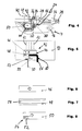
- the sealing device 42 is partial arranged in recesses 44 (see. FIG. 1 or FIG. 5), which on the top of the two opposite side plates 8, 10 are formed.
- Any sealing device has one consisting of a substantially rigid material Pressure piece 46, made of a substantially elastically deformable material existing sealing element 48, one with a lateral end portion of the Application roller 20 and / or the contact element in contact with the doctor element 30 50 and one arranged on the contact element 50 from an elastic deformable material formed penetration element 52 (see. Fig. 5 to 8), in which the doctor element 30 penetrates with its end portion.
- barriers 49 the contact elements 50 are fastened to the base body 28.
- the penetration element 52 consists of silicone and is in one recess 54 formed on the contact element 50 (see FIG. 5 or FIG. 8) arranged.
- the contact element 50 consists of a wear-resistant and temperature-resistant material such as Pertinax, which is so-called Hard paper deals; however, it could also be made of Kevlar.
- the contact element 50 has a rounded contour at an end section - on the left in FIG. 4 on, which is adapted to the shape of the recess 44.
- the contact element 50 can be together with the Base body 28 moved in the direction of arrows 40 in an adjustment range to an optimal position of the doctor element 30 relative to the application roller 20 to be able to adjust.
- a sealing cord 56 is in one on the elastic sealing member 48 trained elongated recess 58 inserted in the form of a groove (Fig. 5) and is in the assembled state by a clamping force applied by the pressure piece 46 pressed.
- the sealing cord 56 serves to seal between the housing 4 and the base body 28 of the doctor device 24 in the region of the side plates 8, 10 and in the region of the side plate 14 and extends essentially over the entire length of the application roller 20 and the side plate 14 (see FIG. 1).
- the Sealing cord 56 runs in a groove 60 which, like FIG. 1 and FIGS. 4 and 5 illustrate in the opposite side plates 8 and 10 and the Side plate 14 is formed.
- FIG. 5 shows, the pressure piece 46 by means of clamping screws, not shown, each in a threaded bore formed in the side plate 10 62 are arranged by turning the clamping screws with a force are applied so that the pressure piece 46 and the elastic sealing element 48 pressed together with the sealing cord 56 and by means of elastic sealing element 48 transmit a force to the contact element 50 is, whereby the contact element on the side face of the applicator roller 20 is pressed.
- FIGS. 9 and 10 illustrate a first embodiment of an inventive Applicator roller 20, part of which is shown.
- the field of Surface of the applicator roller 20 are a variety of those made by drilling Recesses 64 are provided.
- a coating on the surface the application roller 20 has been applied, which fixed to the application roller 20 attached.
- the coating consists of a hard material and is, for example from the company Hartec, Schmeienstr. 51, sites on the cold market, Germany, offered under the name ICER ®.
- the coating ensures a very low tendency to stick, low adhesion, minimal formation of deposits and shows at the same time a high chemical resistance to acids and alkalis.
- PVD physical vapor deposition
- a recess 64 is circular. Each Recess 64 each has a spherical surface. From Fig. 10 is can be seen that the dome-shaped surface of a recess 64 by means of a Drill with a diameter of one millimeter has been made and the Surface accordingly has a radius of one millimeter. The depth of one The recess is 0.14 millimeters. The outer diameter of a recess is 0.69 millimeters.
- the recesses 64 are arranged in several parallel to one another and transversely to the direction of rotation of the applicator roller, shown in FIG. 9 Arranged rows.
- the row spacing is calculated from the center of the Recesses 64 a millimeter.
- the distance between a recess 64 and one adjacent recess 64 of the same row is also one millimeter.
- the recesses in adjacent rows are each offset by 0.5 mm arranged to each other. This surface structure allows a very even application on a substrate and also a relatively small application each Achieve unit area on the substrate.
- FIGS. 9 and 10 illustrate an alternative embodiment of a Applicator roller 20, in which recesses 66 are also produced by drilling in the area of your surface.
- the drill for making the recesses 66 is oblique and not vertical arranged so that recesses 66 with an asymmetrical surface shape arise, as Figs. 13 and 14 illustrate in an enlarged view.
- the longitudinal axis of the drill 68 does not intersect the axis of rotation 22 of the application roller 20th
- FIG. 15 and 16 show a further alternative embodiment of a Applicator roller 20 with recesses 70, which are also made by drilling become.
- the drill is also inclined relative to the surface of the application roller arranged and additionally obliquely to the axis of rotation 22 of the applicator roller 20 arranged so that a surface structure according to FIG. 16 is formed.
Landscapes
- Coating Apparatus (AREA)
- Engineering & Computer Science (AREA)
- Mechanical Engineering (AREA)
- Inking, Control Or Cleaning Of Printing Machines (AREA)
Abstract
Description
- Fig. 1
- das Gehäuse einer erfindungsgemäßen Rad-Auftragsvorrichtung bestehend aus einer Grundplatte und drei Seitenplatten in einer Draufsicht;
- Fig. 2
- das in Fig. 1 dargestellte Ausführungsbeispiel in einer Seitenansicht;
- Fig. 3
- das in den Fig. 1 und 2 dargestellte Ausführungsbeispiel mit einer schematisch dargestellten Auftragswalze in einer weiteren Seitenansicht;
- Fig. 4
- einen Abschnitt des Ausführungsbeispiels gemäß Fig. 1 bis 3 in einer weiteren Teilschnittdarstellung, aus der die Dichtungseinrichtung und Rakeleinrichtung ersichtlich sind;
- Fig. 5
- eine Draufsicht auf die Abdichtungseinrichtung gemäß Fig. 4;
- Fig. 6
- ein Druckstück der Abdichtungseinrichtung in einer Draufsicht;
- Fig. 7
- ein erfindungsgemäßes elastisch verformbares Dichtungselement mit einer länglichen Ausnehmung zur Aufnahme einer Dichtungsschnur in einer Draufsicht;
- Fig. 8
- ein Kontaktelement mit einem elastischen Eindringelement in einer Draufsicht;
- Fig. 9
- einen vergrößerten Abschnitt der Auftragswalze mit einer Vielzahl von Ausnehmungen;
- Fig. 10
- eine Ausnehmung in einer Schnittdarstellung;
- Fig. 11
- eine Auftragswalze mit einer alternativen Oberflächenstruktur;
- Fig. 12
- eine seitliche Darstellung der in Fig. 11 dargestellten Auftragswalze;
- Fig. 13
- eine vergrößerte Ansicht eines Ausschnitts gemäß Fig. 11;
- Fig. 14
- einen vergrößten Abschnitt gemäß Fig. 12 zusammen mit einem Bohrer zur Herstellung der Ausnehmungen in einer vergrößerten Darstellung;
- Fig. 15
- ein weiteres alternatives Ausführungsbeispiel einer Auftragswalze mit mehreren Ausnehmungen;
- Fig. 16
- einen vergrößerten Ausschnitt aus Fig. 15.
- 2
- Auftragsvorrichtung
- 4
- Gehäuse
- 6
- Grundplatte
- 8
- Seitenplatte
- 10
- Seitenplatte
- 12
- Seitenplatte
- 14
- Seitenplatte
- 18
- Leimbecken
- 20
- Auftragswalze
- 22
- Drehachse
- 24
- Rakeleinrichtung
- 26
- Ausnehmung
- 28
- Grundkörper
- 30
- Rakelelement
- 32
- Klemmkörper
- 36
- Verstellschraube
- 38
- Vierkant
- 40
- Pfeile
- 42
- Dichtungseinrichtung
- 44
- Ausnehmungen
- 46
- Druckstück
- 48
- Dichtungselement
- 49
- Schranke
- 50
- Kontaktelement
- 52
- Eindringelement
- 54
- Ausnehmung
- 56
- Dichtungsschnur
- 58
- Ausnehmung
- 60
- Nut
- 62
- Gewindebohrung
- 64
- Ausnehmung
- 66
- Ausnehmung
- 68
- Bohrer
- 70
- Ausnehmung
Claims (15)
- Rad-Auftragsvorrichtung zum Auftragen eines Fluids auf ein Substrat, mit einer an einem Gehäuse (4) rotierbar gelagerten Auftragswalze (20), deren Umfangsfläche mit einem Fluid beaufschlagbar ist und an der das Substrat so vorbeibewegt werden kann, daß Fluid von der Oberfläche der Auftragswalze (20) auf das Substrat übertragen wird,dadurch gekennzeichnet, daß ein elastisch verformbares Dichtungselement (48) zwischen dem Druckstück (46) und dem Kontaktelement (50) angeordnet ist.mit einer mit der Auftragswalze (20) zusammenwirkenden Rakeleinrichtung (24) mit einem Rakelelement (30), das so relativ zu der Oberfläche der Auftragswalze (20) angeordnet ist, daß auf der rotierenden Auftragswalze (20) befindliches Fluid teilweise abgestreift wird,und mit mindestens einer im seitlichen Endbereich der Auftragswalze (20) angeordneten Dichtungseinrichtung (42) zum seitlichen Abdichten zwischen dem Rakelelement (30) und/oder der Auftragswalze (20) und dem Gehäuse (4) der Auftragsvorrichtung (2), wobei die Dichtungseinrichtung (42) ein mit der Auftragswalze (20) und/oder dem Rakelelement (30) in Kontakt stehendes, mittels eines Druckstücks (46) verspannbares Kontaktelement (50) aufweist,
- Auftragsvorrichtung nach Anspruch 1 oder dem Oberbegriff des Anspruchs 1, dadurch gekennzeichnet daß das Kontaktelement (50) der Dichtungseinrichtung (42) aus einem elastisch verformbaren Material gebildet ist oder ein aus einem elastisch verformbaren Material gebildetetes Eindringelement (52) aufweist, so daß das Rakelelement (30) der Rakeleinrichtung (24) in das Kontaktelement (50) oder das Eindringelement (52) eindringen kann.
- Rad-Auftragsvorrichtung zum Auftragen eines Fluids auf ein Substrat, insbesondere nach Anspruch 1 oder 2,
mit einer an einem Gehäuse (4) rotierbar gelagerten Auftragswalze (20), deren Umfangsfläche mit einem Fluid beaufschlagbar ist und an der das Substrat so vorbeibewegbar ist, daß Fluid von der Oberfläche der Auftragswalze (20) auf das Substrat übertragen wird,
dadurch gekennzeichnet, daßdie Auftragswalze (20) an ihrem Umfangsbereich eine Vielzahl von durch Bohren hergestellte Ausnehmungen (64, 66, 70) und eine Beschichtung aufweist. - Auftragsvorrichtung nach Anspruch 3 oder dem Oberbegriff des Anspruchs 3, dadurch gekennzeichnet, daß das Gehäuse (4) eine separate Grundplatte (6) und mehrere separate Seitenplatten (8, 10, 12, 14) aufweist, welche zur Herstellung des Gehäuses (4) aneinander befestigbar sind.
- Auftragsvorrichtung nach Anspruch 1, 2, 3 oder 4,
dadurch gekennzeichnet, daß das elastische Dichtungselement (48) eine Ausnehmung (58) aufweist, in die eine Dichtungsschnur (56) zur Abdichtung zwischen dem Gehäuse (4) und der Rakeleinrichtung (24) einlegbar ist. - Auftragsvorrichtung nach wenigstens einem der vorstehenden Ansprüche,
dadurch gekennzeichnet, daß das Kontaktelement (50) aus einem verschleißfesten und temperaturbeständigen Material wie Hartpapier (Pertinax) besteht. - Auftragsvorrichtung nach mindestens einem der vorstehenden Ansprüche, dadurch gekennzeichnet, daß das Eindringelement (52) des Kontaktelements (50) aus Polytetrafluoräthylen (PTFE) besteht.
- Auftragsvorrichtung nach wenigstens einem der vorstehenden Ansprüche,
dadurch gekennzeichnet, daß das Druckstück (46) der Dichtungseinrichtung (42) mittels zweier Spannschrauben verspannbar ist, welche sich durch in einer Seitenplatte (8, 10) ausgebildete Bohrungen (62) erstrecken. - Auftragsvorrichtung nach einem der Ansprüche 3 bis 8,
dadurch gekennzeichnet, daß die an dem Umfangsbereich der Auftragswalze (20) ausgebildeten Ausnehmungen (64) jeweils eine kalottenförmige Oberfläche aufweisen. - Auftragsvorrichtung nach Anspruch 9,
dadurch gekennzeichnet, daß jede Ausnehmung (64) etwa einen Durchmesser von 0,69 Millimeter, eine Tiefe von 0,14 Millimeter und die kalottenförmige Oberfläche einen Radius von etwa 1 Millimeter aufweist. - Auftragsvorrichtung nach Anspruch 9 oder 10,
dadurch gekennzeichnet, daß eine Vielzahl von Ausnehmungen (64) in parallelen Reihen angeordnet sind und in Rotationsrichtung der Auftragswalze (20) gesehen versetzt zueinander angeordnet sind. - Auftragsvorrichtung nach einem der Ansprüche 3 bis 11,
dadurch gekennzeichnet, daß die an dem Umfangsbereich der Auftragswalze (20) ausgebildeten Ausnehmungen (66) jeweils eine asymetrische Oberflächenform aufweisen, die daraus resultiert, daß während des Bohrens die Längsachse des Bohrers (68) schräg zur Oberfläche der Auftragswalze (20) angeordnet ist. - Auftragsvorrichtung nach einem der Ansprüche 4 bis 12,
dadurch gekennzeichnet, daß die Grundplatte (6) und die Seitenplatten (8, 10) im wesentlichen eine rechteckige Form aufweisen und mittels Schraubverbindung aneinander befestigt sind. - Auftragsvorrichtung nach Anspruch 13,
dadurch gekennzeichnet, daß zwei gegenüberliegende Seitenplatten (8,10,12,14) je eine Ausnehmung (44) zur Aufnahme einer Dichtungseinrichtung (42) aufweisen. - Auftragsvorrichtung nach einem der Ansprüche 3 bis 14,
dadurch gekennzeichnet, daß die Beschichtung aus einem metallischen Hartstoff besteht.
Applications Claiming Priority (2)
| Application Number | Priority Date | Filing Date | Title |
|---|---|---|---|
| DE29903308U | 1999-02-24 | ||
| DE29903308U DE29903308U1 (de) | 1999-02-24 | 1999-02-24 | Rad-Auftragsvorrichtung |
Publications (2)
| Publication Number | Publication Date |
|---|---|
| EP1031383A2 true EP1031383A2 (de) | 2000-08-30 |
| EP1031383A3 EP1031383A3 (de) | 2006-04-05 |
Family
ID=8069878
Family Applications (1)
| Application Number | Title | Priority Date | Filing Date |
|---|---|---|---|
| EP00102528A Withdrawn EP1031383A3 (de) | 1999-02-24 | 2000-02-07 | Rad-Auftragsvorrichtung |
Country Status (2)
| Country | Link |
|---|---|
| EP (1) | EP1031383A3 (de) |
| DE (1) | DE29903308U1 (de) |
Cited By (1)
| Publication number | Priority date | Publication date | Assignee | Title |
|---|---|---|---|---|
| CN112974145A (zh) * | 2021-02-22 | 2021-06-18 | 吴品露 | 一种多次挤压均匀刮胶的汽车地毯加工涂胶装置 |
Family Cites Families (8)
| Publication number | Priority date | Publication date | Assignee | Title |
|---|---|---|---|---|
| DE1718005U (de) | 1955-12-14 | 1956-03-01 | Wilhelm Stritz | Klebeapparat fuer streifen. |
| US4398494A (en) | 1982-02-02 | 1983-08-16 | Beloit Corporation | End dam seal for blade type fountain coaters |
| US4590855A (en) * | 1984-06-18 | 1986-05-27 | Printco Industries, Ltd. | Reverse angle doctor blade assembly with stationary end seal |
| DE3713027A1 (de) | 1987-04-16 | 1988-11-17 | Frankenthal Ag Albert | Rasterwalze fuer ein offsetfarbwerk, sowie verfahren zur herstellung einer derartigen rasterwalze |
| US4821672A (en) * | 1987-06-22 | 1989-04-18 | Nick Bruno | Doctor blade assembly with rotary end seals and interchangeable heads |
| DE3828929C2 (de) | 1988-08-26 | 1999-04-22 | Festo Ag & Co | Vorrichtung zum Auftragen von Klebstoff auf zu verklebende Oberflächen |
| US5662042A (en) * | 1996-06-10 | 1997-09-02 | Paper Converting Machine Co. | Method of operating ink unit for printing press |
| DE59800788D1 (de) * | 1998-01-28 | 2001-07-05 | Fischer & Krecke Gmbh & Co | Dichtung für Kammerrakel |
-
1999
- 1999-02-24 DE DE29903308U patent/DE29903308U1/de not_active Expired - Lifetime
-
2000
- 2000-02-07 EP EP00102528A patent/EP1031383A3/de not_active Withdrawn
Non-Patent Citations (1)
| Title |
|---|
| None |
Cited By (2)
| Publication number | Priority date | Publication date | Assignee | Title |
|---|---|---|---|---|
| CN112974145A (zh) * | 2021-02-22 | 2021-06-18 | 吴品露 | 一种多次挤压均匀刮胶的汽车地毯加工涂胶装置 |
| CN112974145B (zh) * | 2021-02-22 | 2021-12-21 | 南京塑九汽车内饰有限公司 | 一种多次挤压均匀刮胶的汽车地毯加工涂胶装置 |
Also Published As
| Publication number | Publication date |
|---|---|
| EP1031383A3 (de) | 2006-04-05 |
| DE29903308U1 (de) | 1999-09-30 |
Similar Documents
| Publication | Publication Date | Title |
|---|---|---|
| EP0297268A2 (de) | Vorrichtung zum Auftragen von flüssigen Klebstoffen auf ein Substrat | |
| DE19743210A1 (de) | Klinge | |
| DE19722117C2 (de) | Beschichtung poröser Träger | |
| EP0647749A1 (de) | Auftragvorrichtung für Mörtel | |
| DE4016662A1 (de) | Fluessigkeitsuebertragungseinheit | |
| DE3429049C2 (de) | ||
| EP0744220A2 (de) | Schlitzdüse | |
| DE69511051T2 (de) | Druckmaschine mit Rakelklinge mit Abdichtungsstreifen | |
| DE2305120A1 (de) | Rakel fuer tiefdruckmaschinen | |
| DE2604422C2 (de) | Vorrichtung zum Aufbringen eines Kunststoff-Sicherungsbelages auf das Gewinde einer Metallschraube | |
| EP0906788A2 (de) | Rakeleinrichtung für eine Vorrichtung zum Auftragen eines flüssigen bis pastösen Mediums auf einen sich vorbeibewegenden Untergrund | |
| DE3828929C2 (de) | Vorrichtung zum Auftragen von Klebstoff auf zu verklebende Oberflächen | |
| DE29903308U1 (de) | Rad-Auftragsvorrichtung | |
| EP0600435B1 (de) | Farbmesser-Lamelle und Farbmesserträger für einen Farbkasten einer Rotationsdruckmaschine | |
| EP0454280B1 (de) | Rasterwalze für ein Auftragswerk mit einer Näpfchengravur | |
| EP0056067A1 (de) | Vorrichtung zum Aufbringen einer dünnen Schicht eines Beschichtungsmaterials auf eine laufende Materialbahn | |
| DE3308066C1 (de) | Farbdosiervorrichtung fuer eine Farbkastenwalze | |
| EP3590854B1 (de) | System aus einem standteller und einer auflage und direktdruckmaschine | |
| DE4209385A1 (de) | Pressmaschine fuer elektronische komponenten des chip-types | |
| DE29521909U1 (de) | Schlitzdüse | |
| DE2107081C3 (de) | Vorrichtung zum Auftragen mikrodünner Streifenüberzüge auf die Oberfläche eines isolierenden Trägers mit einer auswechselbaren Auftragkammer für eine fließfähige, insbesondere zur Herstellung elektrischer Widerstände geeignete Kunststoffmasse | |
| DE3829208A1 (de) | Vorrichtung zur haftvermittlerbeschichtung von als armierung fuer extrudierte gummiprofilleisten dienenden bandstahl od. dgl. | |
| DE3149295A1 (de) | Vorrichtung zum gleichmaessigen verteilen einer hochviskosen fluessigkeit | |
| DE2944393C2 (de) | Vorrichtung zum Aufbringen einer dünnen Schicht eines Beschichtungsmaterials auf eine laufende Materialbahn | |
| EP0573801B1 (de) | Waschvorrichtung für einen Gummituchzylinder einer Druckmaschine |
Legal Events
| Date | Code | Title | Description |
|---|---|---|---|
| PUAI | Public reference made under article 153(3) epc to a published international application that has entered the european phase |
Free format text: ORIGINAL CODE: 0009012 |
|
| AK | Designated contracting states |
Kind code of ref document: A2 Designated state(s): AT BE CH CY DE DK ES FI FR GB GR IE IT LI LU MC NL PT SE |
|
| AX | Request for extension of the european patent |
Free format text: AL;LT;LV;MK;RO;SI |
|
| PUAL | Search report despatched |
Free format text: ORIGINAL CODE: 0009013 |
|
| AK | Designated contracting states |
Kind code of ref document: A3 Designated state(s): AT BE CH CY DE DK ES FI FR GB GR IE IT LI LU MC NL PT SE |
|
| AX | Request for extension of the european patent |
Extension state: AL LT LV MK RO SI |
|
| AKX | Designation fees paid | ||
| STAA | Information on the status of an ep patent application or granted ep patent |
Free format text: STATUS: THE APPLICATION IS DEEMED TO BE WITHDRAWN |
|
| 18D | Application deemed to be withdrawn |
Effective date: 20061006 |
|
| REG | Reference to a national code |
Ref country code: DE Ref legal event code: 8566 |