EP1025974A2 - Mécanisme de commande d'un élément de valve pour un appareil de moulage par injection - Google Patents
Mécanisme de commande d'un élément de valve pour un appareil de moulage par injection Download PDFInfo
- Publication number
- EP1025974A2 EP1025974A2 EP99103331A EP99103331A EP1025974A2 EP 1025974 A2 EP1025974 A2 EP 1025974A2 EP 99103331 A EP99103331 A EP 99103331A EP 99103331 A EP99103331 A EP 99103331A EP 1025974 A2 EP1025974 A2 EP 1025974A2
- Authority
- EP
- European Patent Office
- Prior art keywords
- piston
- cylinder
- elongated
- valve
- pin plate
- Prior art date
- Legal status (The legal status is an assumption and is not a legal conclusion. Google has not performed a legal analysis and makes no representation as to the accuracy of the status listed.)
- Granted
Links
- 230000007246 mechanism Effects 0.000 title claims abstract description 38
- 238000001746 injection moulding Methods 0.000 title claims abstract description 25
- 238000002347 injection Methods 0.000 claims abstract description 23
- 239000007924 injection Substances 0.000 claims abstract description 23
- 239000012530 fluid Substances 0.000 claims description 25
- 229920000139 polyethylene terephthalate Polymers 0.000 description 37
- 239000005020 polyethylene terephthalate Substances 0.000 description 37
- 239000000463 material Substances 0.000 description 31
- 230000004888 barrier function Effects 0.000 description 20
- 238000001816 cooling Methods 0.000 description 6
- 238000010438 heat treatment Methods 0.000 description 6
- 229920000219 Ethylene vinyl alcohol Polymers 0.000 description 5
- 125000006850 spacer group Chemical group 0.000 description 5
- 229910000831 Steel Inorganic materials 0.000 description 4
- 239000010959 steel Substances 0.000 description 4
- 239000004677 Nylon Substances 0.000 description 3
- 239000004715 ethylene vinyl alcohol Substances 0.000 description 3
- 229920001778 nylon Polymers 0.000 description 3
- -1 polyethylene terephthalate Polymers 0.000 description 3
- 239000000155 melt Substances 0.000 description 2
- 238000000465 moulding Methods 0.000 description 2
- 229920003023 plastic Polymers 0.000 description 2
- 239000004033 plastic Substances 0.000 description 2
- VGGSQFUCUMXWEO-UHFFFAOYSA-N Ethene Chemical compound C=C VGGSQFUCUMXWEO-UHFFFAOYSA-N 0.000 description 1
- 239000005977 Ethylene Substances 0.000 description 1
- 229920000297 Rayon Polymers 0.000 description 1
- 235000013361 beverage Nutrition 0.000 description 1
- 239000000498 cooling water Substances 0.000 description 1
- 238000000034 method Methods 0.000 description 1
- 238000012986 modification Methods 0.000 description 1
- 230000004048 modification Effects 0.000 description 1
- 230000008569 process Effects 0.000 description 1
- 238000005086 pumping Methods 0.000 description 1
- 229920006163 vinyl copolymer Polymers 0.000 description 1
- XLYOFNOQVPJJNP-UHFFFAOYSA-N water Substances O XLYOFNOQVPJJNP-UHFFFAOYSA-N 0.000 description 1
Images


Classifications
-
- B—PERFORMING OPERATIONS; TRANSPORTING
- B29—WORKING OF PLASTICS; WORKING OF SUBSTANCES IN A PLASTIC STATE IN GENERAL
- B29C—SHAPING OR JOINING OF PLASTICS; SHAPING OF MATERIAL IN A PLASTIC STATE, NOT OTHERWISE PROVIDED FOR; AFTER-TREATMENT OF THE SHAPED PRODUCTS, e.g. REPAIRING
- B29C45/00—Injection moulding, i.e. forcing the required volume of moulding material through a nozzle into a closed mould; Apparatus therefor
- B29C45/16—Making multilayered or multicoloured articles
- B29C45/1603—Multi-way nozzles specially adapted therefor
-
- B—PERFORMING OPERATIONS; TRANSPORTING
- B29—WORKING OF PLASTICS; WORKING OF SUBSTANCES IN A PLASTIC STATE IN GENERAL
- B29C—SHAPING OR JOINING OF PLASTICS; SHAPING OF MATERIAL IN A PLASTIC STATE, NOT OTHERWISE PROVIDED FOR; AFTER-TREATMENT OF THE SHAPED PRODUCTS, e.g. REPAIRING
- B29C45/00—Injection moulding, i.e. forcing the required volume of moulding material through a nozzle into a closed mould; Apparatus therefor
- B29C45/17—Component parts, details or accessories; Auxiliary operations
- B29C45/26—Moulds
- B29C45/27—Sprue channels ; Runner channels or runner nozzles
- B29C45/28—Closure devices therefor
- B29C45/2806—Closure devices therefor consisting of needle valve systems
- B29C45/281—Drive means therefor
-
- B—PERFORMING OPERATIONS; TRANSPORTING
- B29—WORKING OF PLASTICS; WORKING OF SUBSTANCES IN A PLASTIC STATE IN GENERAL
- B29C—SHAPING OR JOINING OF PLASTICS; SHAPING OF MATERIAL IN A PLASTIC STATE, NOT OTHERWISE PROVIDED FOR; AFTER-TREATMENT OF THE SHAPED PRODUCTS, e.g. REPAIRING
- B29C45/00—Injection moulding, i.e. forcing the required volume of moulding material through a nozzle into a closed mould; Apparatus therefor
- B29C45/16—Making multilayered or multicoloured articles
- B29C45/1603—Multi-way nozzles specially adapted therefor
- B29C2045/1612—Multi-way nozzles specially adapted therefor using needle valves with at least four positions
-
- B—PERFORMING OPERATIONS; TRANSPORTING
- B29—WORKING OF PLASTICS; WORKING OF SUBSTANCES IN A PLASTIC STATE IN GENERAL
- B29C—SHAPING OR JOINING OF PLASTICS; SHAPING OF MATERIAL IN A PLASTIC STATE, NOT OTHERWISE PROVIDED FOR; AFTER-TREATMENT OF THE SHAPED PRODUCTS, e.g. REPAIRING
- B29C45/00—Injection moulding, i.e. forcing the required volume of moulding material through a nozzle into a closed mould; Apparatus therefor
- B29C45/17—Component parts, details or accessories; Auxiliary operations
- B29C45/26—Moulds
- B29C45/27—Sprue channels ; Runner channels or runner nozzles
- B29C45/28—Closure devices therefor
- B29C45/2806—Closure devices therefor consisting of needle valve systems
- B29C45/281—Drive means therefor
- B29C2045/2813—Common drive means for several needle valves
-
- B—PERFORMING OPERATIONS; TRANSPORTING
- B29—WORKING OF PLASTICS; WORKING OF SUBSTANCES IN A PLASTIC STATE IN GENERAL
- B29C—SHAPING OR JOINING OF PLASTICS; SHAPING OF MATERIAL IN A PLASTIC STATE, NOT OTHERWISE PROVIDED FOR; AFTER-TREATMENT OF THE SHAPED PRODUCTS, e.g. REPAIRING
- B29C45/00—Injection moulding, i.e. forcing the required volume of moulding material through a nozzle into a closed mould; Apparatus therefor
- B29C45/17—Component parts, details or accessories; Auxiliary operations
- B29C45/26—Moulds
- B29C45/27—Sprue channels ; Runner channels or runner nozzles
- B29C45/28—Closure devices therefor
- B29C45/2806—Closure devices therefor consisting of needle valve systems
- B29C45/281—Drive means therefor
- B29C2045/2831—Needle valves driven by a cam
Definitions
- This invention relates generally to valve gated multi-cavity injection molding apparatus and more particularly to such apparatus including apparatus to simultaneously accurately drive all the valve pins between more than two positions.
- Hydraulic mechanism for actuating injection molding valve pins is well known. However, in some applications such as those involving food, hydraulic fluid is not allowed in the mold. In these cases, pneumatic actuating mechanism is often used, but it does not have sufficient power for some requirements.
- the applicant's U.S. Patent Number 4,212,627 which issued July 15, 1980 shows mechanical mechanism for driving several valve pins simultaneously between the open and closed positions. While this two position actuating mechanism is satisfactory for many applications, it cannot be used for applications such as multi-layer molding where it is necessary to drive the valve pins between three or four positions during each injection cycle.
- Canadian Application Serial Number 2,192,611 to Schramm et al. which was laid open August 20, 1997 also shows previous mechanism for simultaneously driving the valve pins.
- valve gated multi-cavity injection molding apparatus having actuating mechanism to simultaneously accurately position all the valve pins between more than two different positions without requiring hydraulics in the mold.
- the invention provides a multi-cavity injection molding apparatus having at least one melt distribution manifold and a plurality of heated nozzles mounted in a mold with an elongated valve pin reciprocating in a first direction in a central bore in each heated nozzle.
- a valve pin plate is mounted in the mold to reciprocate in a first direction.
- the valve pin plate has the valve pins extending forwardly therefrom and actuator means extending rearwardly therefrom.
- One or more elongated cam members are mounted in the mold adjacent the valve pin plate actuator means to reciprocate in a second direction lateral to the first direction.
- Either the valve pin plate actuator means or the elongated cam member has a plurality of diagonally extending grooves facing the other of the valve pin plate actuator means and the elongated cam member.
- the other of the valve pin plate actuator means and the elongated cam member has a number of laterally projecting slide means. Each of the laterally projecting slide means extends into one of the diagonally extending grooves, whereby movement of the elongated cam member in the second direction moves the valve pin plate actuator means, the valve pin plate and the attached valve pins in the first direction.
- the apparatus includes actuator mechanism to accurately drive the elongated cam member between at least first, second and third positions to accurately drive all the elongated valve pins simultaneously between first, second and third corresponding positions during each injection cycle.
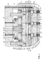
- Figures 1 and 2 show a portion of a valve gated multi-cavity injection molding system or apparatus for molding five layer preforms or other products by a combination of sequential and simultaneous coinjection.
- Two layers of a barrier material such as ethylene vinyl alcohol copolymer (EVOH) or nylon are molded between two outer layers and a central layer of a polyethylene terephthalate (PET) type material.
- a number of heated nozzles 10 are mounted in a mold 12 with their rear ends 14 abutting against the front face 16 of a steel front melt distribution manifold 18.
- Thermal insulating melt transfer spacers 20 extending through openings 22 in the front melt distribution manifold 18 to provide an insulating air space 24 between the front melt distribution manifold 18 and a rear melt distribution manifold 26.
- the mold 12 can have a greater number of plates depending upon the application, in this case only a nozzle retainer plate 28, a manifold retainer plate 30, a spacer plate 32 and a back plate 34 secured together by bolts 36, as well as a cavity retainer plate 38 are shown for ease of illustration.
- the front end 40 of each heated nozzle 10 is aligned with a gate 42 extending through a cooled gate insert 44 to a cavity 46.
- This cavity 46 for making beverage bottle preforms extends between a cavity insert (not shown) and a cooled mold core 47 in a conventional manner.
- Each nozzle is heated by an integral electrical heating element having an electrical terminal 48.
- Each heated nozzle 10 is seated in an opening 50 in the nozzle retainer plate 28 with a rear collar portion 52 of the heated nozzle 10 received in a circular locating seat 54 extending around the opening 50.
- This provides an insulative air space 56 between the heated nozzle 10 and the surrounding mold 12 which is cooled by pumping cooling water through cooling conduits 58.
- the front melt distribution manifold 18 is heated by an integral electrical heating element 60 and is separated from the cooled nozzle retainer plate 28 by an insulative air space 62.
- the rear melt distribution manifold 26 is heated by an integral electrical heating element 64 to a different operating temperature than the front distribution manifold 18.
- the rear melt distribution manifold 26 is spaced by insulative spacers 66 from the manifold retainer plate 30 to provide an insulative air space 68 between them.
- a melt dividing bushing 70 is seated in an opening 72 in the front melt distribution manifold 18 in alignment with each heated nozzle 10.
- a first melt passage 74 branches in the front melt distribution manifold 18 and divides in each melt dividing bushing 70 to extend from a common inlet (not shown) through each heated nozzle 10 to the aligned gate 42.
- a second melt passage 76 branches in the rear melt distribution manifold 26 to extend from a common inlet (not shown) through each melt transfer spacer 20 and each heated nozzle 10 to the aligned gate 42.
- the heated nozzles 10 each have inner and outer annular melt channels extending around a central melt channel 78 as shown in the applicants' Canadian Patent Application Serial Number 2,219,235 entitled “Five Layer Injection Molding Apparatus Having Four Position Valve Member Actuating Mechanism” filed October 23, 1997.
- Each heated nozzle 10 receives an elongated valve pin 80 extending through its central melt channel 78 in alignment with the gate 42.
- the valve pin 80 extends rearwardly through the aligned melt dividing bushing 70 and aligned bores 82 and 84 through the rear melt dividing manifold 26 and the manifold retainer plate 30.
- Each elongated valve pin 80 has a front end 86 which fits in the aligned gate 42 and a rear head 88 which is attached to a valve pin plate 90.
- Leader pins 92 having bushings 94 are secured by screws 96 to extend between the manifold retainer plate 30 and the back plate 34.
- the valve pin plate 90 is mounted in the mold to reciprocate frontwardly and rearwardly on the leader pins 92.
- a support pillar 98 is secured by a screw 100 to the manifold retainer plate 30.
- the valve pin plate 90 has a front portion 102 and a rear portion 104.
- the valve pins 80 are inserted through holes 106 in the front portion 102, and the front and rear portions 102, 104 are then secured together by screws 108 to securely attach the valve pins 80 to the valve pin plate 90.
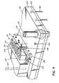
- the valve pin plate 90 has a pair of spaced elongated actuator bars 110 attached to its rear surface 112 by screws 114 to extend parallel to each other.
- a pair of elongated cam bars 116 extend between the pair of elongated actuator bars 110.
- These cam bars 116 which also extend parallel to each other, are mounted in a cam bar retainer plate 118 secured to the back plate 34 by bolts 120.
- each cam bar 116 is mounted to slide longitudinally on a series of linear roller bearings 122 mounted in the cam bar retainer plate 118.
- Another series of roller bearings 124 is mounted on its rear surface 126 which abuts against the front face 128 of the back plate 34.
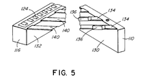
- each of the elongated actuator bars 110 attached to the valve pin plate 90 has a side surface 130 which faces a side surface 132 of the adjacent cam bar 116.
- the side surface 130 of each actuator bar 110 has a number of grooves 134 extending diagonally therein with rectangular slide blocks 136 seated in each diagonal groove 134.
- the slide blocks 136 are securely attached to the actuator bars 110 by bolts 138.
- the side surfaces 132 of the cam bars 116 also have grooves 140 which extend diagonally at the same angle as the grooves 134 in the actuator bars 110.
- the slide blocks 136 project outwardly from the side surface 130 of the actuator bar 110 and fit into the grooves 140 in the adjacent side surface 132 of the adjacent cam bar 116.
- the slide blocks 136 attached to each actuator bar 110 slide in the grooves 140 in the adjacent cam bar 116 which cannot move longitudinally.
- the actuator bars 110, cam bars 116, and slide blocks 136 are treated by a suitable process to be wear resistant. While the slide blocks 136 shown in this embodiment are attached to the actuator bars 110, in other embodiments they can be attached to the cam bars 116 to slide in the grooves 134 in the actuators bars 110.
- the two cam bars 116 are both attached to a yoke member 142 which is driven by actuating mechanism 144 according to one embodiment of the invention having an outer casing 146 attached to the mold 12 by bolts 148.
- the actuating mechanism 144 includes a drive nut 150 which moves along a drive screw 152 as the screw is rotated.
- the drive nut 150 is attached to a cylindrical thrust transmitting tube 154 which is, in turn, attached to the yoke member 142.
- the drive screw 152 having a thrust bearing 156 is driven by a DC motor 158 through a drive belt 160 extending between pulleys 162, 164.
- the actuating mechanism 144 is an electromechanical linear actuator model number made by Jasta-Dynact.
- the electric motor 158 is programmed to drive the cam bars 116 and thus all of the valve pins 80 simultaneously between four different positions during the injection cycle. In other embodiments, the electric motor 158 can be programmed to simultaneously drive the valve pins 80 between three or five different positions according to a different injection cycle.
- the injection molding system is assembled as shown in Figures 1 and 2 and operates to form five layer preforms or other products as follows.
- electrical power is applied to the heating element 60 in the front melt distribution manifold 18 and the heating elements in the heated nozzles 10 to heat them to the operating temperature of the plastic material to be injected through the central melt channel 78 in each heated nozzle 10.
- this material is a polyethylene terephthalate (PET) type material which has a melt temperature of about 565°F.
- Electrical power is also applied to the heating element 64 in the rear melt distribution manifold 26 to heat it to the operating temperature of the plastic material that is injected through the inner annular melt channel in each heated nozzle 10.
- EVOH ethylene vinyl copolymer
- Water is supplied to the cooling conduits 58 to cool the mold 12 and the gate inserts 44.
- Hot pressurized melt is then injected from separate injection cylinders (not shown) into the first and second melt passages 74, 76 according to a predetermined injection cycle.
- the first melt passage 74 branches in the front melt distribution manifold 18 and extends to each melt dividing bushing 70 where it divides again and flows to the central melt channel 78 around the elongated valve pin member 80 as well as to the outer annular melt channel of the aligned heated nozzle 10.
- the second melt passage 76 branches in the rear melt distribution manifold 26 and extends through a central bore 166 in each melt transfer spacer 20 to the inner annular melt channel in each heated nozzle 10.
- the flow of PET from the first melt passage 74 and the barrier material from the second melt passage 76 through each gate 42 into the cavity 46 is controlled by the actuating mechanism 144 reciprocating the elongated valve pins 80 between first, second, third and fourth positions during the injection cycle as follows.
- the valve pin plate 90 and the valve pins 80 attached thereto are in a first forward closed position shown in Figure 1 wherein the front end 86 of each valve pin 80 is seated in the aligned gate 42.
- the program controlling the electric motor 158 according to the injection cycle then activates the electric motor 158 to draw the pair of cam bars 116 a precise distance to the right as seen in Figure 3 and then stop.
- each valve pin 80 is retracted sufficiently to allow PET to flow from the outer annual melt channel in each heated nozzle 10 through the gate 42 into the cavity 46 where part of it adheres to the sides of the cavity 46.
- the electric motor 158 is then again activated to draw the pair of cam bars 116 a precise distance further to the right and then stop. This further retracts the valve pins 80 simultaneously to a third further open position in which both PET from the outer annular melt channel and a barrier material from the inner annular melt channel are coinjected simultaneously through the gates 42 to the cavities 46. The flow of the less viscose barrier material splits the flow of PET into two outer layers.
- the program again activates the electric motor 58 to draw the pair of cam bars 116 another precise distance further to the right. This retracts the valve pins 80 to the fourth fully open position. In this fully open position, the front ends 86 of the valve pins 80 are retracted sufficiently to also allow simultaneous flow of PET from the central melt channels 78 through the gates 42 into the cavities 46. This inner flow of PET, in turn, splits the flow of the barrier material into two layers on both sides of an inner layer of PET.
- the program activates the electric motor 158 in the opposite direction to drive the pair of cam bars 116 a precise distance to the left as seen in Figure 3 to return the valve pins 80 to the second position which stops the flow of PET from the central melt channel 78 and the flow of the barrier material from the inner annular melt channel.
- the electric motor 158 is again activated to drive the pair of cam bars 116 another precise distance further to the left which advances the valve members 80 and returns them to the first closed position.
- the mold 12 is open for ejection. After ejection, the mold 12 is closed and the cycle is repeated continuously every 15 to 30 seconds with a frequency depending upon the wall thickness and the number and size of the cavities 46 and the exact materials being molded.
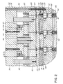
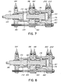
- FIG. 6 - 9 show a portion of a valve gated multi-cavity injection molding system or apparatus having actuating mechanism according to another embodiment of the invention.
- the elements of this embodiment which are the same as in the embodiment described above are described and illustrated using the same reference numerals.
- the nozzles 10, the front and rear manifolds 18, 26, the actuator bars 110 and the cam bars 116 are the same as in the above embodiment and the description of them and their operation need not be repeated.
- the cam bars 116 are driven by a four position hydraulic actuating mechanism 168 rather than the electro-mechanical actuating mechanism 144 described above.
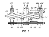
- the hydraulic actuating mechanism 168 comprises a first piston 170 seated in a front cylinder 172, and a second ring piston 174 and a third piston 176 seated in a rear cylinder 178.
- the two cylinders 172, 178 extend in alignment and are formed by steel outer body parts 180 which are secured together by screws 182.
- the first piston 170 has a head portion 184 seated in the front cylinder 172 and a stem portion 186 extending forwardly out of the front cylinder 172 and connected by a pin 188 to the yoke member 142 extending between the two cam bars 116.
- the second ring piston 174 is seated in the rear cylinder 178.
- the third piston 176 has a head portion 190 seated in the rear cylinder 178 and a stem portion 192 extending forwardly through the second ring piston 174 and out of the rear cylinder 178 into the front cylinder 172 to abut against the head portion 184 of the first piston 170.
- first and second hydraulic lines 194, 196 from a controlled source of hydraulic pressure are connected to the front cylinder 172 on opposite sides of the first piston 170.
- a third hydraulic line 198 from the hydraulic pressure source is connected to the rear cylinder 178 in front of the second ring piston 174.
- a fourth hydraulic line 200 from the hydraulic pressure source is connected to the rear cylinder 178 between the second ring piston 174 and the third piston 176.
- a fifth hydraulic line 202 from the hydraulic pressure source is connected to the rear cylinder 178 behind the third piston 176.
- hydraulic lines 194, 196, 198, 200, 202 extend from the source (not shown) which applies hydraulic pressure to the different lines according to a predetermined program controlled according to the injection cycle to reciprocate the valve pins 80 between first, second, third and fourth positions during the injection cycle as follows.
- hydraulic pressure is applied from the second hydraulic line 196 to the front cylinder 172 behind the first piston 170 and from the fifth hydraulic line 202 to the rear cylinder 178 behind the third piston 176 which drives both pistons 170, 176 forwardly to the position shown in Figure 7.
- This drives the valve pin plate 90 and the valve pins 80 attached thereto simultaneously to the first forward closed position shown in Figure 1 wherein the front end 86 of each valve pin 80 is seated in the aligned gate 42.
- the hydraulic pressure from the second hydraulic line 196 is released and hydraulic pressure is applied from the first hydraulic line 194 to the front cylinder 172 in front of the first piston 170 which drives the first piston 170 rearwardly to the position shown in Figure 8.
- each valve pin 80 is retracted sufficiently to allow PET to flow from the outer annular melt channel in each heated nozzle 10 through the aligned gate 42 into the aligned cavity 46 where part of it adheres to the sides of the cavity 46.
- the mold 12 After a short cooling period, the mold 12 is open for ejection. After ejection, the mold 12 is closed and the cycle is repeated continuously every 15 to 30 seconds with a frequency depending upon the wall thickness and the number and size of the cavities 46 and the exact materials being molded.
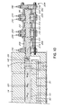
- FIG. 10 shows a portion of a valve gated multi-cavity injection molding system or apparatus having a different four position hydraulic actuating mechanism according to another embodiment of the invention.
- the nozzles 10, the front and rear manifolds 18, 26, the actuator bars 110 and the cam bars 116 are the same as in the previous embodiment and their description need not be repeated.
- the hydraulic actuating mechanism 204 comprises a first piston 206 seated in a front cylinder 208, a second piston 210 seated in a middle cylinder 212, and a third piston 214 seated in a rear cylinder 216.
- the cylinders 208, 212, 216 extend in alignment and are formed by steel outer body parts 218 which are secured together by screws 220.
- the first piston 206 has a head portions 222 seated in the front cylinder 208 and a stem portion 224 extending forwardly out of the front cylinder 208 and connected by a pin 188 to the yoke member 142 extending between the two cam bars 116.
- the second piston 210 has a head portion 228 seated in the middle cylinder 212 with a stem portion 230 extending forwardly out of the middle cylinder 212 into the front cylinder 208 to abut against the head portion 222 of the first piston 206.
- the third piston 214 has a head portion 232 seated in the rear cylinder 216 and a stem portion 234 extending forwardly out of the rear cylinder 216 into the middle cylinder 212 to abut against the head portion 228 of the second piston 210.
- first and second hydraulic lines 236, 238 are connected to the front cylinder 208 on opposite sides of the first piston 206.
- Third and fourth hydraulic lines 240, 242 are connected to the middle cylinder 212 on opposite sides of the second piston 210.
- Fifth and sixth hydraulic lines 244, 246 are connected to the rear cylinder 216 on opposite sides of the third piston 214.
- These hydraulic lines 236, 238, 240, 242, 244 and 246 extend from a source (not shown) which applies hydraulic pressure or exhaust back to a hydraulic tank to the different lines according to a predetermined program controlled according to the injection cycle to reciprocate the valve pins 80 between first, second, third and fourth positions during the injection cycle as follows.
- hydraulic pressure is applied from the second, fourth and sixth hydraulic lines 238, 242, 246 to drive all of the pistons 206, 210, 214 forwardly. Then, hydraulic pressure from the second hydraulic line 238 is released and hydraulic pressure is applied from the first hydraulic line 236 to the front cylinder 208 in front of the first piston 206 which retracts the first piston 206 rearwardly to a second partially open position.
- the hydraulic pressure from the fourth hydraulic line 242 is released which allows the first and second pistons 206, 210 to retract to the third further open position.
- the hydraulic pressure from the sixth hydraulic line 246 is released which allows the pistons 206, 210, 214 to fully retract to the fully open position shown in Figure 10.
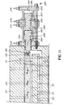
- FIGS 11 - 13 show a portion of a valve gated multi-cavity injection molding system or apparatus having a three position hydraulic actuating mechanism 247 according to a further embodiment of the invention.
- a barrier material such as ethylene vinyl alcohol copolymer (EVOH) or nylon is molded between two outer layers of a polyethylene terephthalate (PET) type material to make preforms or other layered products.
- EVOH ethylene vinyl alcohol copolymer
- PET polyethylene terephthalate
- the actuator bars 110 and cam bars 116 are the same as in the previous embodiments and the nozzles 10 and the front and rear manifolds 18, 26 are similar except that the nozzles only have a single annular melt channel extending around the central melt channel 78 and the PET is supplied to the annular melt channels and the barrier material to the central melt channel 78.
- the hydraulic actuating mechanism 247 comprises a first piston 248 seated in a front cylinder 250 and a second piston 252 seated in a rear cylinder 254.
- the cylinders 250, 254 extend in alignment and are formed by steel outer body parts 256 which are secured together by screws 258.
- the first piston 248 has a head portion 260 seated in the front cylinder 250 and a stem portion 262 extending forwardly out of the front cylinder 250 and connected by a pin 188 to the yoke member 142 extending between the two cam bars 116.
- the second piston 252 has a head portion 264 seated in the rear cylinder 254 with a stem portion 266 extending forwardly out of the rear cylinder 254 into the front cylinder 250 to abut against the head portion 260 of the front piston 248.
- first and second hydraulic lines 268, 270 are connected to the front cylinder 250 on opposite sides of the first piston 248.
- Third and fourth hydraulic lines 272, 274 are connected to the rear cylinder 254 on opposite sides of the second piston 252.
- These hydraulic lines 268, 270, 272, 274 extend from a source (not shown) which applies hydraulic pressure to the different lines according to a predetermined program controlled according to the injection cycle to reciprocate the valve pins 80 between first, second and third positions during the injection cycle as follows.
- each valve pin 80 is retracted sufficiently to allow simultaneous flow of PET from the annular melt channel and a barrier material from the central melt channel 78 in each nozzle 10 through the gates 42 into the cavities 46.
- the flow of the less viscous barrier material splits the flow of PET into two outer layers.
- valve gated injection molding apparatus having actuating mechanism to simultaneously accurately position the valve pins between a number of different positions
- pistons can be driven by pneumatic pressure rather than hydraulic pressure.
Landscapes
- Engineering & Computer Science (AREA)
- Manufacturing & Machinery (AREA)
- Mechanical Engineering (AREA)
- Moulds For Moulding Plastics Or The Like (AREA)
- Injection Moulding Of Plastics Or The Like (AREA)
Applications Claiming Priority (2)
| Application Number | Priority Date | Filing Date | Title |
|---|---|---|---|
| CA002261367A CA2261367C (fr) | 1999-02-08 | 1999-02-08 | Mecanisme d'actionnement d'elements de robinet de moulage par injection |
| CA2261367 | 1999-02-08 |
Publications (3)
| Publication Number | Publication Date |
|---|---|
| EP1025974A2 true EP1025974A2 (fr) | 2000-08-09 |
| EP1025974A3 EP1025974A3 (fr) | 2001-11-28 |
| EP1025974B1 EP1025974B1 (fr) | 2004-04-28 |
Family
ID=4163277
Family Applications (1)
| Application Number | Title | Priority Date | Filing Date |
|---|---|---|---|
| EP99103331A Expired - Lifetime EP1025974B1 (fr) | 1999-02-08 | 1999-02-19 | Mécanisme de commande d'un élément de valve pour un appareil de moulage par injection |
Country Status (9)
| Country | Link |
|---|---|
| US (1) | US6113381A (fr) |
| EP (1) | EP1025974B1 (fr) |
| JP (1) | JP2000238083A (fr) |
| CN (1) | CN1099951C (fr) |
| BR (1) | BR9902484A (fr) |
| CA (1) | CA2261367C (fr) |
| DE (2) | DE69916775T2 (fr) |
| HK (1) | HK1028374A1 (fr) |
| SG (1) | SG84523A1 (fr) |
Cited By (9)
| Publication number | Priority date | Publication date | Assignee | Title |
|---|---|---|---|---|
| EP1184152A1 (fr) * | 2000-09-01 | 2002-03-06 | Mold-Masters Limited | Dispositif de moulage par injection à étages avec ensembles d'entrées d'injection à valve qui sont actionées séparément |
| EP1714769A2 (fr) | 2005-04-22 | 2006-10-25 | Schreck Kunststofftechnik GmbH | Dispositif pour l'ouverture et la fermeture de buses d'injection dans un moule d'injection |
| US7172410B2 (en) | 2003-06-23 | 2007-02-06 | Panos Trakas | Adjustable valve pin assembly |
| US7207790B2 (en) | 2004-07-02 | 2007-04-24 | Panos Trakas | Needle assembly with adjustable gating needle position for injection molding nozzle |
| WO2007079951A1 (fr) * | 2006-01-10 | 2007-07-19 | Günther Heisskanaltechnik Gmbh | Dispositif d'actionnement de pointeaux de vannes dans des dispositifs de moulage par injection comportant des buses a vannes a pointeaux |
| WO2007079836A1 (fr) * | 2005-12-28 | 2007-07-19 | Günther Heisskanaltechnik Gmbh | Dispositif d'actionnement de pointeaux de vannes dans des dispositifs de moulage par injection comportant des buses a vannes a pointeaux |
| US8113818B2 (en) | 2010-03-30 | 2012-02-14 | Panos Trakas | Valve gate system |
| EP3117977A1 (fr) * | 2015-07-14 | 2017-01-18 | Günther Heisskanaltechnik GmbH | Moitié d'outil pour un moule de formage d'une machine à mouler par injection comprenant un système de canaux chauffants |
| DE102017005299B3 (de) | 2017-06-02 | 2018-10-31 | Otto Männer GmbH | Stelleinrichtung zum Verstellen wenigstens einer Ventilnadel einer Spritzgießvorrichtung |
Families Citing this family (30)
| Publication number | Priority date | Publication date | Assignee | Title |
|---|---|---|---|---|
| CA2317779A1 (fr) * | 2000-09-06 | 2002-03-06 | Mold-Masters Limited | Corps de vanne pour le moulage par injection |
| CA2358148A1 (fr) | 2001-10-03 | 2003-04-03 | Mold-Masters Limited | Buse d'injection |
| CN100448646C (zh) * | 2002-07-30 | 2009-01-07 | 标准模具(2007)有限公司 | 用于注塑装置中的热流道的阀针导向和对准系统 |
| CN1833853B (zh) * | 2005-03-18 | 2010-12-08 | 亚洲光学股份有限公司 | 可封阻浇口的射出模具 |
| KR101353883B1 (ko) * | 2005-12-21 | 2014-02-18 | 알베마를 코포레이션 | 브롬화 음이온성 스티렌계 중합체 및 이의 제조 |
| ATE478897T1 (de) * | 2005-12-21 | 2010-09-15 | Albemarle Corp | Herstellung brominierter styren-polymere oder - harze |
| DE202006000036U1 (de) * | 2006-01-02 | 2007-05-16 | Günther Heisskanaltechnik Gmbh | Betätigungsvorrichtung für Verschlußnadeln in Spritzgießvorrichtungen mit Nadelverschlußdüsen |
| DE202006014168U1 (de) * | 2006-09-12 | 2008-02-14 | Günther Heisskanaltechnik Gmbh | Betätigungsvorrichtung für Verschlussnadeln in Spritzgießvorrichtungen mit Nadelverschlussdüsen |
| DE202006000373U1 (de) * | 2006-01-10 | 2007-05-16 | Günther Heisskanaltechnik Gmbh | Betätigungsvorrichtung für Verschlußnadeln in Spritzgießvorrichtungen mit Nadelverschlußdüsen |
| US7553150B2 (en) | 2006-06-19 | 2009-06-30 | Mold-Masters (2007) Limited | Valve-pin actuating device for a hot runner apparatus |
| EP2044133B1 (fr) | 2006-07-20 | 2015-01-28 | Albemarle Corporation | Technologie de traitement pour la récupération de polymères styréniques bromés à partir de mélanges réactifs dans lesquels ils sont formés et/ou conversion de ces mélanges en granules ou en pastilles |
| TW200817447A (en) | 2006-08-22 | 2008-04-16 | Albemarle Corp | Terminating bromination of styrenic polymer in a bromination reaction mixture |
| DE102006040182A1 (de) * | 2006-08-26 | 2008-03-06 | Mht Mold & Hotrunner Technology Ag | Verfahren zur Herstellung eines mehrschichtigen Vorformlings sowie Düse hierfür |
| US7770760B2 (en) * | 2007-02-12 | 2010-08-10 | Illinois Tool Works Inc. | Modular system for the delivery of hot melt adhesive or other thermoplastic materials |
| US7766646B2 (en) * | 2007-06-22 | 2010-08-03 | Mold-Masters (2007) Limited | Injection molding apparatus with plate actuation of valve pins |
| US8220362B2 (en) * | 2007-10-23 | 2012-07-17 | Husky Injection Molding Systems Ltd. | Cam apparatus for valve stem actuation |
| JP5498486B2 (ja) | 2008-06-06 | 2014-05-21 | アルベマール・コーポレーシヨン | 低分子量臭素化ポリマー、それらの製作プロセス、および熱可塑性配合物におけるそれらの使用 |
| JP2011183741A (ja) * | 2010-03-10 | 2011-09-22 | Aoki Technical Laboratory Inc | ホットランナー金型におけるノズル開閉装置 |
| US10899056B2 (en) | 2011-11-23 | 2021-01-26 | Synventive Molding Solutions, Inc. | Non-coaxially mounted electric actuator and transmission |
| DE102012003574A1 (de) | 2012-02-27 | 2013-05-02 | Otto Männer Innovation GmbH | Stelleinrichtung zum Verstellen der Nadelventile einer Heißkanal-Spritzgießvorrichtung |
| CN102700079A (zh) * | 2012-06-12 | 2012-10-03 | 深圳市精控机电有限公司 | 用于塑胶模具阀式热流道的针阀装置 |
| ITTO20120578A1 (it) * | 2012-06-28 | 2013-12-29 | Inglass Spa | Apparecchiatura di stampaggio ad iniezione di materie plastiche |
| EP3342575B2 (fr) | 2013-07-08 | 2022-11-16 | Synventive Molding Solutions, Inc. | Actionneur électrique et transmission montés de façon non coaxiale |
| PT2918389T (pt) * | 2014-03-10 | 2018-04-17 | Inglass Spa | Placa de fixação de um molde, de um aparelho de moldagem por injeção de material plástico |
| DE102015007903B4 (de) | 2015-06-22 | 2019-01-31 | Audi Ag | Verfahren zur Herstellung eines Werkstücks |
| CN108367474B (zh) | 2015-11-23 | 2020-10-23 | 赫斯基注塑系统有限公司 | 阀杆致动 |
| CA3037567C (fr) | 2016-10-05 | 2023-01-03 | Husky Injection Molding Systems Ltd. | Buse de canal chauffe a materiaux multiples |
| WO2018194961A1 (fr) * | 2017-04-18 | 2018-10-25 | Synventive Molding Solutions, Inc. | Entraînement de tige de soupape linéaire à linéaire pendant un cycle d'injection |
| IT201800003490A1 (it) * | 2018-03-13 | 2019-09-13 | Inglass Spa | Apparecchiatura di stampaggio ad iniezione di materie plastiche |
| CN113043558A (zh) * | 2021-03-31 | 2021-06-29 | 广州华煜网络科技有限公司 | 一种可调节的注塑冷却用输送带 |
Citations (3)
| Publication number | Priority date | Publication date | Assignee | Title |
|---|---|---|---|---|
| US4212627A (en) * | 1978-12-08 | 1980-07-15 | Gellert Jobst U | Injection molding valve pin actuator mechanism |
| CA2192611A1 (fr) * | 1996-02-19 | 1997-08-20 | Klaus Schramm | Methode de pulverisation pour la fabrication d'articles moules a trois epaisseurs |
| DE19611880A1 (de) * | 1996-03-26 | 1997-10-02 | Zahoransky Formenbau Gmbh | Spritzgießwerkzeug |
Family Cites Families (5)
| Publication number | Priority date | Publication date | Assignee | Title |
|---|---|---|---|---|
| CA1153524A (fr) * | 1980-10-15 | 1983-09-13 | Jobst U. Gellert | Mecanisme a double effet pour actionneur de soupape de moulage par injection |
| JPS6347549A (ja) * | 1986-08-11 | 1988-02-29 | Aisin Warner Ltd | フエイルセ−フ機能を備えた自動変速機 |
| CA2068543C (fr) * | 1992-05-11 | 1999-11-09 | Jobst Ulrich Gellert | Appareil de moulage par coinjection a mecanisme de manoeuvre axial rotatif |
| EP0832729B1 (fr) * | 1996-09-30 | 2000-03-08 | EUROTOOL Beheer B.V. | Dispositif de buse à obturation pour moulage par injection |
| CA2219235C (fr) * | 1997-10-23 | 2006-12-12 | Mold-Masters Limited | Appareil de moulage par injection de cinq couches ayant un actionneur de soupape a quatre positions |
-
1999
- 1999-02-08 CA CA002261367A patent/CA2261367C/fr not_active Expired - Fee Related
- 1999-02-19 EP EP99103331A patent/EP1025974B1/fr not_active Expired - Lifetime
- 1999-02-19 DE DE69916775T patent/DE69916775T2/de not_active Expired - Lifetime
- 1999-02-19 DE DE19907116A patent/DE19907116A1/de not_active Withdrawn
- 1999-02-22 US US09/257,141 patent/US6113381A/en not_active Expired - Lifetime
- 1999-02-25 SG SG9901255A patent/SG84523A1/en unknown
- 1999-03-05 JP JP11058946A patent/JP2000238083A/ja active Pending
- 1999-03-08 CN CN99102921A patent/CN1099951C/zh not_active Expired - Fee Related
- 1999-04-22 BR BR9902484-5A patent/BR9902484A/pt not_active Application Discontinuation
-
2000
- 2000-11-25 HK HK00107572A patent/HK1028374A1/xx not_active IP Right Cessation
Patent Citations (3)
| Publication number | Priority date | Publication date | Assignee | Title |
|---|---|---|---|---|
| US4212627A (en) * | 1978-12-08 | 1980-07-15 | Gellert Jobst U | Injection molding valve pin actuator mechanism |
| CA2192611A1 (fr) * | 1996-02-19 | 1997-08-20 | Klaus Schramm | Methode de pulverisation pour la fabrication d'articles moules a trois epaisseurs |
| DE19611880A1 (de) * | 1996-03-26 | 1997-10-02 | Zahoransky Formenbau Gmbh | Spritzgießwerkzeug |
Cited By (14)
| Publication number | Priority date | Publication date | Assignee | Title |
|---|---|---|---|---|
| EP1184152A1 (fr) * | 2000-09-01 | 2002-03-06 | Mold-Masters Limited | Dispositif de moulage par injection à étages avec ensembles d'entrées d'injection à valve qui sont actionées séparément |
| US7172410B2 (en) | 2003-06-23 | 2007-02-06 | Panos Trakas | Adjustable valve pin assembly |
| USRE41280E1 (en) | 2003-06-23 | 2010-04-27 | Panos Trakas | Adjustable valve pin assembly |
| US7207790B2 (en) | 2004-07-02 | 2007-04-24 | Panos Trakas | Needle assembly with adjustable gating needle position for injection molding nozzle |
| EP1714769A2 (fr) | 2005-04-22 | 2006-10-25 | Schreck Kunststofftechnik GmbH | Dispositif pour l'ouverture et la fermeture de buses d'injection dans un moule d'injection |
| EP1714769A3 (fr) * | 2005-04-22 | 2006-11-02 | Schreck Kunststofftechnik GmbH | Dispositif pour l'ouverture et la fermeture de buses d'injection dans un moule d'injection |
| WO2007079836A1 (fr) * | 2005-12-28 | 2007-07-19 | Günther Heisskanaltechnik Gmbh | Dispositif d'actionnement de pointeaux de vannes dans des dispositifs de moulage par injection comportant des buses a vannes a pointeaux |
| US7815431B2 (en) | 2005-12-28 | 2010-10-19 | Gunther Heisskanaltechnik Gmbh | Actuating device for shut-off needles in injection molding devices comprising needle shut-off nozzles |
| WO2007079951A1 (fr) * | 2006-01-10 | 2007-07-19 | Günther Heisskanaltechnik Gmbh | Dispositif d'actionnement de pointeaux de vannes dans des dispositifs de moulage par injection comportant des buses a vannes a pointeaux |
| US8113818B2 (en) | 2010-03-30 | 2012-02-14 | Panos Trakas | Valve gate system |
| US8449799B2 (en) | 2010-03-30 | 2013-05-28 | Panos Trakas | Valve gate system |
| EP3117977A1 (fr) * | 2015-07-14 | 2017-01-18 | Günther Heisskanaltechnik GmbH | Moitié d'outil pour un moule de formage d'une machine à mouler par injection comprenant un système de canaux chauffants |
| DE102017005299B3 (de) | 2017-06-02 | 2018-10-31 | Otto Männer GmbH | Stelleinrichtung zum Verstellen wenigstens einer Ventilnadel einer Spritzgießvorrichtung |
| US11225004B2 (en) | 2017-06-02 | 2022-01-18 | Otto Männer GmbH | Actuating device for adjusting at least one valve needle of an injection molding apparatus |
Also Published As
| Publication number | Publication date |
|---|---|
| EP1025974A3 (fr) | 2001-11-28 |
| DE69916775T2 (de) | 2004-09-23 |
| CA2261367A1 (fr) | 2000-08-08 |
| CN1099951C (zh) | 2003-01-29 |
| JP2000238083A (ja) | 2000-09-05 |
| CN1262990A (zh) | 2000-08-16 |
| DE69916775D1 (de) | 2004-06-03 |
| HK1028374A1 (en) | 2001-02-16 |
| DE19907116A1 (de) | 2000-08-10 |
| EP1025974B1 (fr) | 2004-04-28 |
| US6113381A (en) | 2000-09-05 |
| BR9902484A (pt) | 2000-03-14 |
| SG84523A1 (en) | 2001-11-20 |
| CA2261367C (fr) | 2008-04-22 |
Similar Documents
| Publication | Publication Date | Title |
|---|---|---|
| CA2261367C (fr) | Mecanisme d'actionnement d'elements de robinet de moulage par injection | |
| EP0911134B1 (fr) | Dispositif de moulage par injection avec une soupape à quatre positions pour la fabrication d'articles à cinq couches | |
| EP1126963B1 (fr) | Procede de moulage par injection de trois couches avec co-injection sequentielle et simultanee | |
| EP0911138B1 (fr) | Dispositif de moulage par injection ayant des douilles pour le transfert de masse fondue interposées entre les distributeurs | |
| EP0911135B1 (fr) | Dispositif de moulage par injection avec un canal de coulée débouchant sur la face frontale de l'aiguille | |
| CA2068543C (fr) | Appareil de moulage par coinjection a mecanisme de manoeuvre axial rotatif | |
| JP3258282B2 (ja) | スプルーゲート式5層射出成形装置 | |
| EP0443387A1 (fr) | Système de moulage par injection avec buses chargées par ressorts | |
| CA2137178C (fr) | Installation de moulage par injection a entrees commandees par obturateur | |
| EP0916468B1 (fr) | Dispositif de moulage par injection ayant des douilles pour transférer et distribuer une masse fondue | |
| US5942257A (en) | Multi-layer injection molding apparatus having three position valve member | |
| CA2264224A1 (fr) | Moule a injection a empreintes multiples separant la fonte a l'avant des busettes | |
| MXPA99002251A (en) | Mechanism of actuation of valve member for molding by inyecc | |
| CA2010381A1 (fr) | Appareil de moulage par injection sequentielle reglee par soupape rotative | |
| WO2000051803A1 (fr) | Appareil de moulage par injection a empreintes multiples separant la matiere fondue a proximite de la partie avant de la buse | |
| MXPA99000290A (en) | Molding apparatus by injection of multiple layers that has a three-position valve member | |
| MXPA98008713A (en) | Injection molding apparatus that has transfer bushings of bath fused between multip |
Legal Events
| Date | Code | Title | Description |
|---|---|---|---|
| PUAI | Public reference made under article 153(3) epc to a published international application that has entered the european phase |
Free format text: ORIGINAL CODE: 0009012 |
|
| AK | Designated contracting states |
Kind code of ref document: A2 Designated state(s): AT BE CH CY DE DK ES FI FR GB GR IE IT LI LU MC NL PT SE Kind code of ref document: A2 Designated state(s): DE ES FR IT LU NL PT |
|
| AX | Request for extension of the european patent |
Free format text: AL;LT;LV;MK;RO;SI |
|
| PUAL | Search report despatched |
Free format text: ORIGINAL CODE: 0009013 |
|
| AK | Designated contracting states |
Kind code of ref document: A3 Designated state(s): AT BE CH CY DE DK ES FI FR GB GR IE IT LI LU MC NL PT SE |
|
| AX | Request for extension of the european patent |
Free format text: AL;LT;LV;MK;RO;SI |
|
| RIC1 | Information provided on ipc code assigned before grant |
Free format text: 7B 29C 45/17 A, 7B 29C 45/16 B, 7B 29C 45/28 B, 7B 29C 45/22 B |
|
| 17P | Request for examination filed |
Effective date: 20020513 |
|
| AKX | Designation fees paid |
Free format text: DE ES FR IT LU NL PT |
|
| 17Q | First examination report despatched |
Effective date: 20021018 |
|
| GRAP | Despatch of communication of intention to grant a patent |
Free format text: ORIGINAL CODE: EPIDOSNIGR1 |
|
| RIN1 | Information on inventor provided before grant (corrected) |
Inventor name: CHU, SIMON Inventor name: GELLERT, JOBST ULRICH |
|
| GRAS | Grant fee paid |
Free format text: ORIGINAL CODE: EPIDOSNIGR3 |
|
| GRAA | (expected) grant |
Free format text: ORIGINAL CODE: 0009210 |
|
| AK | Designated contracting states |
Kind code of ref document: B1 Designated state(s): DE ES FR IT LU NL PT |
|
| PG25 | Lapsed in a contracting state [announced via postgrant information from national office to epo] |
Ref country code: NL Free format text: LAPSE BECAUSE OF FAILURE TO SUBMIT A TRANSLATION OF THE DESCRIPTION OR TO PAY THE FEE WITHIN THE PRESCRIBED TIME-LIMIT Effective date: 20040428 Ref country code: IT Free format text: LAPSE BECAUSE OF FAILURE TO SUBMIT A TRANSLATION OF THE DESCRIPTION OR TO PAY THE FEE WITHIN THE PRE;WARNING: LAPSES OF ITALIAN PATENTS WITH EFFECTIVE DATE BEFORE 2007 MAY HAVE OCCURRED AT ANY TIME BEFORE 2007. THE CORRECT EFFECTIVE DATE MAY BE DIFFERENT FROM THE ONE RECORDED.SCRIBED TIME-LIMIT Effective date: 20040428 |
|
| REF | Corresponds to: |
Ref document number: 69916775 Country of ref document: DE Date of ref document: 20040603 Kind code of ref document: P |
|
| PG25 | Lapsed in a contracting state [announced via postgrant information from national office to epo] |
Ref country code: ES Free format text: LAPSE BECAUSE OF FAILURE TO SUBMIT A TRANSLATION OF THE DESCRIPTION OR TO PAY THE FEE WITHIN THE PRESCRIBED TIME-LIMIT Effective date: 20040808 |
|
| NLV1 | Nl: lapsed or annulled due to failure to fulfill the requirements of art. 29p and 29m of the patents act | ||
| ET | Fr: translation filed | ||
| PG25 | Lapsed in a contracting state [announced via postgrant information from national office to epo] |
Ref country code: LU Free format text: LAPSE BECAUSE OF NON-PAYMENT OF DUE FEES Effective date: 20050219 |
|
| PLBE | No opposition filed within time limit |
Free format text: ORIGINAL CODE: 0009261 |
|
| STAA | Information on the status of an ep patent application or granted ep patent |
Free format text: STATUS: NO OPPOSITION FILED WITHIN TIME LIMIT |
|
| 26N | No opposition filed |
Effective date: 20050131 |
|
| PG25 | Lapsed in a contracting state [announced via postgrant information from national office to epo] |
Ref country code: PT Free format text: LAPSE BECAUSE OF NON-PAYMENT OF DUE FEES Effective date: 20040928 |
|
| REG | Reference to a national code |
Ref country code: FR Ref legal event code: TP |
|
| REG | Reference to a national code |
Ref country code: FR Ref legal event code: PLFP Year of fee payment: 17 |
|
| PGFP | Annual fee paid to national office [announced via postgrant information from national office to epo] |
Ref country code: DE Payment date: 20150122 Year of fee payment: 17 |
|
| PGFP | Annual fee paid to national office [announced via postgrant information from national office to epo] |
Ref country code: FR Payment date: 20150220 Year of fee payment: 17 |
|
| REG | Reference to a national code |
Ref country code: DE Ref legal event code: R119 Ref document number: 69916775 Country of ref document: DE |
|
| REG | Reference to a national code |
Ref country code: FR Ref legal event code: ST Effective date: 20161028 |
|
| PG25 | Lapsed in a contracting state [announced via postgrant information from national office to epo] |
Ref country code: DE Free format text: LAPSE BECAUSE OF NON-PAYMENT OF DUE FEES Effective date: 20160901 Ref country code: FR Free format text: LAPSE BECAUSE OF NON-PAYMENT OF DUE FEES Effective date: 20160229 |