EP1025390B1 - Articles with diffuse reflection of light from light fibers - Google Patents
Articles with diffuse reflection of light from light fibers Download PDFInfo
- Publication number
- EP1025390B1 EP1025390B1 EP98915182A EP98915182A EP1025390B1 EP 1025390 B1 EP1025390 B1 EP 1025390B1 EP 98915182 A EP98915182 A EP 98915182A EP 98915182 A EP98915182 A EP 98915182A EP 1025390 B1 EP1025390 B1 EP 1025390B1
- Authority
- EP
- European Patent Office
- Prior art keywords
- light
- article
- sheet material
- fiber
- reflective sheet
- Prior art date
- Legal status (The legal status is an assumption and is not a legal conclusion. Google has not performed a legal analysis and makes no representation as to the accuracy of the status listed.)
- Expired - Lifetime
Links
Images

Classifications
-
- G—PHYSICS
- G02—OPTICS
- G02B—OPTICAL ELEMENTS, SYSTEMS OR APPARATUS
- G02B6/00—Light guides; Structural details of arrangements comprising light guides and other optical elements, e.g. couplings
- G02B6/0001—Light guides; Structural details of arrangements comprising light guides and other optical elements, e.g. couplings specially adapted for lighting devices or systems
- G02B6/0005—Light guides; Structural details of arrangements comprising light guides and other optical elements, e.g. couplings specially adapted for lighting devices or systems the light guides being of the fibre type
- G02B6/001—Light guides; Structural details of arrangements comprising light guides and other optical elements, e.g. couplings specially adapted for lighting devices or systems the light guides being of the fibre type the light being emitted along at least a portion of the lateral surface of the fibre
-
- Y—GENERAL TAGGING OF NEW TECHNOLOGICAL DEVELOPMENTS; GENERAL TAGGING OF CROSS-SECTIONAL TECHNOLOGIES SPANNING OVER SEVERAL SECTIONS OF THE IPC; TECHNICAL SUBJECTS COVERED BY FORMER USPC CROSS-REFERENCE ART COLLECTIONS [XRACs] AND DIGESTS
- Y10—TECHNICAL SUBJECTS COVERED BY FORMER USPC
- Y10S—TECHNICAL SUBJECTS COVERED BY FORMER USPC CROSS-REFERENCE ART COLLECTIONS [XRACs] AND DIGESTS
- Y10S385/00—Optical waveguides
- Y10S385/901—Illuminating or display apparatus
Definitions
- This invention is directed in general to articles that are illuminated using light fibers and methods for making and using these articles. More particularly, the invention is directed to articles with structures to provide enhanced diffuse reflection of light from light fibers and to methods for making and using these articles.
- Light fibers are often useful for illuminating an area that is remote from a light source by conducting light through the fiber by total internal reflection. These fibers can be made with varying diameter and length. Light fibers having a diameter of 5 mm or greater are often referred to as "large core optical fibers" and have been used, for example, as accents for architectural features, as lights for areas that would otherwise be hazardous due to the presence of, for example, the heat or electricity present with incandescent or fluorescent lights (e.g., underwater or poolside lights), and as building or vehicle interior lights.
- Light can be emitted from light fibers in a number of ways.
- Most light fibers provide at least some "end-light”.
- Many light fibers are designed to maximize internal reflection so that the primary function of the light fiber is to conduct light from a light source to a remote location. The light emitted by this type of light fiber is primarily "end-light”.
- light can be emitted radially along a portion of or over the entire length of the light fiber.
- This light is often referred to as "side-light".
- Most light fibers emit this type of light, which is often due to imperfections in the light fiber, including imperfections in the core and cladding of the light fiber and/or an imperfect interface between the core and cladding.
- this type of light emission is minimized; however, there is typically at least some minimal amount of "side-light” which is often seen as a faint glow around the light fiber.
- the "side-light” is typically a diffuse light.
- Light fibers may also be formed which purposefully include mechanisms or structures for extracting light along the length or a portion of the length of the fiber. For example, imperfections in the core or cladding or at the interface between the core and cladding may be introduced to interrupt the internal reflection of at least a portion of the light.
- These light fibers can be used, for example, as visible or decorative articles for providing a ribbon of light along a distance. Light extracted in this manner is typically diffuse.
- Another method of extracting light includes redirecting light in a controlled manner out of the light fiber by means of optical elements introduced into the light fiber core or applied directly thereto, such that the function of the light fiber is to conduct light from a source to a specific location other than the end of the fiber.
- This method of extraction may provide diffuse light; but is more commonly used to produce directed light.
- Such fibers may be used to provide directed light at particular points or positions, for example, on a screen or other object.
- Diffuse light which is emitted from a light source, such as an incandescent or fluorescent light bulb, in the desk lamp, however, is typically emitted in all directions. This is an inefficient use of the light because not all of the light is properly directed. A significant portion of the light is radiated away from the desired illumination location.
- Light fibers can be an efficient way to transmit light and illuminate desired areas using light from a distant light source. However, just as with other light sources, light fibers may not efficiently direct the emitted light, especially if the light is "side-light” or diffusely extracted.
- US-A-5,416,608 describes an illumination system that includes a light guide formed of a cylindrical shaped light-transmitting material, a light source for introducing light into the light guide from the lengthwise direction of the light guide, a light-diffusing portion formed on the circumference of the light guide in the lengthwise direction of the light guide and a slit portion positioned opposite the light-diffusing portion.
- the present invention relates to articles having a light fiber for illumination and diffusive reflective material around a portion of the light fiber to direct the light from the light fiber in a desired set of directions and provide diffuse illumination.
- the illumination in the desired set of directions is brighter than if the light fiber were used alone.
- the present invention is also directed to methods of using and manufacturing these articles.
- One embodiment of the invention is an article configured for emitting diffuse light in a predetermined set of directions when coupled with a light source.
- the article includes a light fiber having a light receiving end coupled to the light source and a diffuse reflective sheet material disposed around at least a portion of the light fiber to direct at least a portion of the light emitted by the light fiber toward the predetermined set of directions.
- the light fiber emits light when coupled to the light source.
- Another embodiment of the invention is an illuminated article which includes . a light source, a light fiber having a light receiving end which is positioned to receive light from the light source and a diffuse reflective sheet material which is disposed around at least a portion of the light fiber to direct light toward a predetermined set of directions.
- a further embodiment is a method of making a diffusive illumination device which includes disposing a diffuse reflective sheet material around at least a portion of a light fiber.
- Yet another embodiment is a method of providing diffuse illumination in a predetermined set of directions.
- the method includes disposing a diffuse reflective sheet material around at least a portion of a light fiber to direct light emitted from the light fiber in the predetermined set of directions and coupling a light source to a receiving end of the light fiber.
- the invention is directed to articles having a light fiber which provides diffuse light in a desired set of directions.
- the invention is also directed to methods for making and using these articles.
- the term "light” is intended to include any form of electromagnetic radiation, but particularly radiation in the spectrum of visible light (approximately 400 to 700 nm wavelength). While the present invention is not so limited, an understanding of various aspects of the invention is best gained through a discussion of various application examples in which the light fiber is a large core optical fiber. Other light fibers including small core optical fibers may also be used.
- the embodiments described below and illustrated in the drawings typically include only a single light fiber, it will be understood that multiple light fibers could also be used in place of the single light fiber.
- Specular reflection refers to mirror-like reflection, in which light is reflected at an angle equal but opposite to that of the incident radiation.
- diffuse reflection provides reflective luminance over a range of angles, regardless of the angle that the incident radiation makes with respect to the macroscopic surface of the diffuse reflective sheet material. It is this property of diffuse reflective sheet material that allows such material to be used to reflect even highly directed light and provide diffuse light over an illumination area.
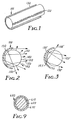
- an article 100 for emitting diffuse light in a desired set of directions includes a light fiber 120 and a diffuse reflective sheet material 130 which is provided around at least a portion of the light fiber.
- a cross-sectional view, Figure 2, of the article 100 shows that a portion of the light which is emitted from the light fiber 120 is reflected by the diffuse reflective sheet material 130 and eventually is directed away from the light fiber 120 and the diffuse reflective sheet material 130.
- the region of the light fiber 120 which is surrounded by the diffuse reflective sheet material 130 can be chosen so that light from the light fiber 120 is emitted from the article only in a desired set of directions (i.e., one or more directions).
- the light seen by an observer includes light rays 140 directly exiting the light fiber 120 and light rays 150 that have been reflected by the diffuse reflective sheet material 130.
- the light rays 150 may reflect more than once off the diffuse reflective sheet material 130.
- the diffuse reflective sheet material is in direct contact with the light fiber. In other embodiments, the diffuse reflective sheet material 130 is spaced apart from the light fiber 120 (as shown in Figure 2).
- Figure 2 illustrates a light fiber 120 which emits "side-light” or light diverted from the light fiber by diffuse light extraction techniques.
- diffuse reflective sheet material may also be used with a light fiber having directed light extractors.
- Figure 3 illustrates one particular embodiment of the invention with a light fiber 120' which is oriented so that the directed light extractors (not shown) in the light fiber direct light 145' toward a diffuse reflective sheet material 130'.
- Light 150' is then reflected off the diffuse reflective sheet material 130' over a range of directions. In some cases, light may be reflected by the diffuse reflective sheet material 130' several times before it finally escapes.
- the use of diffuse reflective sheet material 130 with the light fiber 120 may increase the brightness of the light directed in the desired set of directions as compared to light produced by a light fiber without the diffuse reflective sheet material 130.
- the brightness is increased by at least 10%, more preferably by at least 25%, even more preferably by at least 50%, and most preferably by at least 100%. In some cases, the brightness increases by 200% or more.
- the light fiber 220 may be placed in a bracket or holder 210 having a channel 215 around the light fiber, as shown in Figures 4A and 4B.
- the diffuse reflective sheet material 230 may be disposed on the inner surface of the channel 215 for reflecting light away from the holder 210.
- the holder 210 may also include a connecting neck 211 and a support or foot 212, which can be fastenably mounted to a wall or panel or other supporting structure (not shown).
- a plurality of supports 212 may be provided along the length of the light fiber 220.
- the support 212 may be a single device having a length comparable to the length of the light fiber 220 and/or the diffuse reflective sheet material 230.
- the light fiber 220 may be shaped in a desired pattern.
- the light fiber 220 may be, for example, frictionally fitted or adhesively mounted in the channel 215, so that it remains in place.
- Figure 4A shows a circular design for channel 215 and Figure 4B shows a square design for channel 215. It will be understood that other shapes and configurations may be similarly used for the channel 215 and holder 210.
- a perspective view of the light fiber 220 and holder 210 is presented in Figure 5.
- the diffuse reflective sheet material 230 is provided on the inner surfaces of the channel 215 and extends for a distance along the length of the light fiber 220.
- the diffuse reflective sheet material 230 may extend the entire length of the channel 215, particularly when uniform illumination is desired.
- a light fiber 320 may be positioned within a structure 360 which has one or more walls 370, as shown in Figure 6.
- the structure 360 may be in the form of a box, as shown in Figure 6, or may be formed in other shapes as desired.
- the diffuse reflective sheet material 330 is provided on at least a portion of the walls 370. There are a variety of methods for providing the diffuse reflective sheet material 330 on the walls 370 including, but not limited to, attachment by fasteners, adhesives, and/or friction.
- the structure 360 may include a covering (not shown) or a portion of the walls 370 which is transparent or translucent. This covering or portion of the walls may be colored. When light is emitted from the light fiber 320 and reflected from the diffuse reflective sheet material 330, the transparent or translucent covering or portion of the walls 370 becomes luminous.
- the structure 360 includes a translucent region, such as covering or portion of the walls 370, it may be desirable that the luminous intensity be uniform across that the translucent region.
- a low-transmittance (e.g., less that 30% transmittance) non-absorbing material such as PlexiglassTM.
- Light emitted by the fiber is then forced to bounce many times within the structure before exiting the translucent portion.
- the diffuse reflective sheet material 330 can be used as a light reflective lining for channel lettering, that is, hollow letters, numerals, symbols, or other figures formed in three dimensions and used, for example, in signs.
- the channel lettering is lit from within by the light fiber and typically has a transparent or translucent front covering and/or walls.
- Figure 6 illustrates a channel letter 300, in the shape of the letter "T", with the cover removed.
- light is provided to the interior of channel letter 300 by a light fiber 320 from the end of light fiber 320 (i.e. "end-light”).
- An external light source 380 is coupled to a light receiving end of the light fiber 320 to illuminate the light fiber.
- the diffuse reflective sheet material 330 covers the inside of channel letter 300, which may be fabricated from any formable material, for example, sheet metal, glass, fiberglass, wood, plastic, or other polymeric material.
- the light fiber 320 may be formed roughly in the shape of the channel letter 300, although this is not required.
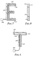
- Figure 7 illustrates another embodiment of a three-dimensional channel letter 500, this time in the shape of the letter "E", with the front cover removed.
- An external light source 580 is provided to illuminate the light fiber 520.
- the light from the light fiber 520 is "side-light" which may optionally be extracted by either diffuse or directed light extractor structures in the light fiber. If directed light extraction is used, then preferably the extracted light is directed toward the portion of the channel letter 500 upon which the diffuse reflective sheet material 530 is provided.
- Figure 8 is a side view of the channel letter 500, showing a cover 515 in place on the front of the channel letter.
- the cover 515 and/or other portions of the channel letter 500 may be transparent or translucent and can be clear, tinted, or colored and disposed on the face of the letter that is to be seen by-a viewer.
- more than one of the walls of the channel letter are transparent or translucent.
- all of the walls except for the back sidewall may be transparent or translucent to allow light to radiate in all directions except backwards.
- the channel letters may be used, for example, to create signs. Individual light fibers may be used for each channel letter. Alternatively, a single light fiber may be used for two or more channel letters or two or more light fibers could be used in any of the channel letters.
- light fibers may be used in the articles of the invention.
- Particularly suitable light fibers are prepared from polymeric materials and are commercially available from sources such as 3M Company (St. Paul, MN), Lumenyte International, Inc. (Costa Mesa, CA), Fiberstars, Inc. (Fremont, CA), Bridgestone Corp. (Tokyo, Japan), Rohm and Haas Co. (Philadelphia, PA), and Mitsubishi Rayon Co., Ltd. (Tokyo, Japan).
- the light fiber 600 typically includes a core 610, a cladding 620, and an optional jacket 630.
- a core 610 may be formed from a polymeric material, including methacrylates, such as n-butyl methacrylate and 2ethylhexyl methacrylate.
- the core may, for example, be prepared by copolymerizing at least one methacrylate monomer derived from the esterification of methacrylic acid with an alcohol having at least 4 carbon atoms and an ethylenically-unsaturated, free-radical polymerizable crosslinking agent.
- Particularly useful methacrylate monomers derived from the esterification of methacrylic acid with an alcohol having at least 4 carbon atoms include, for example, n-butyl methacrylate, n-hexyl methacrylate, 2-ethylhexyl methacrylate, noctyl methacrylate, iso-octyl methacrylate, n-decyl methacrylate, and dodecyl methacrylate, and combinations thereof.
- Preferred methacrylate monomers include n-butyl methacrylate, n-hexyl methacrylate, 2-ethylhexyl methacrylate, n-octyl methacrylate, and combinations thereof.
- Crosslinking agents useful in light fibers are those ethylenically-unsaturated, free-radical polymerizable compounds possessing two or more free-radical polymerizable, ethylenically-unsaturated reactive moieties, such as, for example, acrylate, methacrylate, allyl, or styryl groups, or the like.
- Preferred crosslinking agents are dimethacrylates and diallyl compounds, most preferably dimethacrylate compounds.
- Useful dimethacrylate compounds include, for example, hexanediol dimethacrylate, ethylene glycol dimethacrylate, diethlylene glycol dimethacrylate, triethylene glycol dimethacrylate, tetraethylene glycol dimethacrylate, propylene glycol dimethacrylate, trimethylol propane dimethacrylate, and methacrylate-terminated oligomers such as polyethylene glycol dimethacrylate and polypropylene oxide dimethacrylate, and combinations thereof
- Preferred dimethacrylate crosslinking agent include diethylene glycol dimethacrylate, triethylene glycol dimethacrylate, tetraethylene glycol dimethacrylate, propylene glycol dimethacrylate, and combinations thereof.
- one suitable core material includes a 1:1 mixture by weight of n-butyl methacrylate and 2-ethylhexyl methacrylate, which, in turn, can contain 0.05% by weight triethylene glycol dimethacrylate crosslinking agent and 0.2% by weight di(4-t-butylcyclohexyl)peroxydicarbonate (Perkadox 16TM, Akzo Nobel Chemicals, Inc., Chicago, IL) thermal initiator. Additional materials and examples are presented in U.S. Patent No. 5,225,166, incorporated herein by reference.
- the core 610 may be made from a flowable material which can, over time, flow around the inner surface of the cladding 620 to form an outer surface of the core 610 which is complementary to the inner surface of the cladding 620.
- core materials include, for example, the methacrylate core materials described above.
- the core may be formed by allowing raw core material to flow into the cladding and then polymerizing the core material in situ.
- a fluid having the same or nearly the same index of refraction can be included between the core and the cladding to help ensure proper optical contact between the core 610 and the cladding 620.
- This fluid may also be used even if the core flows around the cladding.
- Suitable fluids include, for example, a siloxane copolymer (PS 785, Petrarch Silanes, United Chemical Technologies, Inc., Bristol, PA), having an index of refraction (1.465 at 583 nm) nearly identical to the core.
- Other suitable index matching fluids are known in the art.
- the cladding 620 can be formed from a variety of different compounds.
- fluoropolymer tubing has been found to be useful as a cladding for the lightfiber.
- suitable fluoropolymer tubing includeTeflon-100TM fluorinated ethylene polymer tubing (FEP tubing, DuPont Chemicals Co. Fluoropolymer Division, Wilmington, DE), TeflonTM poly(tetrafluoroethylene) (PTFE) tubing (DuPont), THV tubing (a terpolymer of tetrafluoroethylene, hexafluoropropylene, and vinylidene fluoride, available from Dyneon, Inc., St. Paul, MN) or other similar commercially-available highly fluorinated polymeric tubing (e.g., tubing from Zeus Industrial Products, Inc., Raritan, NJ).
- the tubing is a heat-shrinkable tubing.
- the core 610 is disposed within the cladding 620 after the inner surface of the cladding is formed.
- the core 610 may be disposed in the cladding 620 by a variety of methods, including, for example, sliding a solid core into the cladding, or pouring a liquid core or core material into the cladding and optionally solidifying or polymerizing the core or core material. If the cladding 620 is heat shrinkable, it may be more tightly formed around the core 610 by application of heat.
- End-light light fibers useful in the invention are commercially available from, for example, 3M Company (St. Paul, MN) or Lumenyte International Corp. (Costa Mesa, CA), which often have diameters from about 5 mm to about 20 mm.
- light fibers are available in diameters of 7 mm, 9 mm, 12 mm, and 18 mm.
- So-called side-light light fibers are also commercially available from 3M Company (St. Paul, MN) or Lumenyte International Corp. (Costa Mesa, CA). Many of these light fibers, however, do not provide brightness equivalent to, for example, a neon light. Methods of achieving bright light fibers with diffuse light extraction are known.
- the light fibers are prepared by roughening the interior of the cladding. Rough or uneven areas of the cladding cause increased light extraction from the sides of the light fiber, because each depression or protrusion is a location at which light can be scattered away from the core.
- the degree of roughening of the cladding may be provided in a controlled, graded manner prior to filling the cladding such that light emitted by the light fiber is uniform in brightness over the length of the light fiber.
- the greatest amount of light in the light fiber is available for extraction immediately adjacent to the light source. Diminishing amounts of light are available further down the core because light has already been extracted.
- Graded extraction is preferably carried out so that the least amount of light extraction takes place closest to the light source and the greatest amount takes place farthest away from the source.
- light sources may be provided at both ends of the light fiber.
- the degree of roughening of the cladding interior preferably is the greatest at the middle of the light fiber, at a point equidistant from both light sources, if the light sources are of equal intensity.
- the light fiber is flexible. This allows the light fiber to be formed into a variety of shapes even after the light fiber has been made.
- the diffuse reflective sheet material is also flexible, particularly if the diffuse reflective sheet material is in direct contact with the light fiber.
- the light fiber and/or the diffuse reflective sheet material may be stiff or difficult to bend. In these cases, the light fiber is typically produced in the desired shape and cannot later be changed.
- a variety of diffuse reflective materials are known including, for example, white inorganic pigments in the form of a pressed cake, ceramic tile or opal glass. These materials may be expensive, stiff and brittle.
- Diffuse reflective sheet materials include microvoided particle-filled sheets that are diffusely reflective due to differences in refractive index of the particles, the surrounding matrix, and air-filled voids created or enlarged by, for example, stretching.
- microporous materials made from, for example, sintered polytetrafluoroethylene (PTFE), made in sheet form, can also act as diffuse reflective material.
- PTFE sintered polytetrafluoroethylene
- Preferred diffuse reflective sheet materials for use in the invention include any sheet material having a reflectivity of at least about 90%, preferably at least about 92%, and more preferably at least about 94%, as measured according to ASTM E 1164-94 at a wavelength of 550 nm.
- Specific sheet materials useful in the invention include, but are not limited to, sintered poly(tetrafluoroethylene) as described in U. S. Patent No. 5,596,450; filled polyolefin reflective sheets such as those described in European Patent Application No. 724,181; biaxially stretched white polyester laminated film such as is described in U. S. Patent No.
- TyvekTM nonwoven polyethylene fabric DuPont Co., Wilmington, DE
- MelinexTM titania-filled microvoided polyethylene terephthalate ICI Plastics, Wilmington, DE
- ScotchCalTM vinyl sheet material (3M Company, St.
- TIPS sheet material comprises a microporous polyolefin material such as described in U. S. Patent Nos. 4,539,251, 4,726,989, and 4,867,881, incorporated herein by reference, which may be referred to as a TIPS sheet material.
- TIPS means "thermally induced phase separation.”
- TIPS sheet material typically includes a thermoplastic polymeric structure having a plurality of cells with adjacent cells being interconnected by passageways to provide a network of communicating pores. This structure is oriented in at least one direction.
- the thermoplastic polymeric structure may be substantially homogeneous or the porosity of the structure may exhibit a gradient therethrough.
- the cells typically include void spaces encased by fibrous, lacy, or semi-continuous boundaries.
- Microporous TIPS sheet materials can be prepared from known thermoplastic polymers including olefinic, condensation and oxidation polymers.
- Representative olefinic polymers include high- and low-density polyethylene, polypropylene poly-vinyl polymers, butadiene-containing polymers, and acrylate containing polymers such as poly(methyl methacrylate).
- Condensation polymers include polyesters such as polyethylene terephthalate) (PET) and poly(butylene terephthalate) (PBT); polyamides such as NylonTM 6, Nylon 11, Nylon 13, and Nylon 66; polycarbonates; and polysulfones.
- Poly(phenylene oxide) is representative of the oxidation polymers which can form TIPS sheet materials.
- Blends of the above thermoplastic polymers can also be used.
- TIPS sheet materials useful in the invention comprise polyolefins, more preferably polyethylene and polypropylene, and most preferably. polypropylene.
- Microporous TIPS sheet materials can be prepared using a diluent component that is miscible with the polymer component at a temperature above the melting point of the polymer component but is immiscible at a temperature below the melting point of the polymer.
- the TIPS sheet material is formed by heating the diluent and polymer above the melting point of the polymer and then cooling the material until a phase separation (either solid/liquid or liquid/liquid) occurs.
- the diluent may be removed by, for example, extraction with a volatile solvent to leave "diluent-out" TIPS sheet material. Alternatively, the diluent may be retained ("diluent-in" TIPS sheet material).
- the TIPS sheet material may be stretched to increase the size of the micropores.
- this may result in the formation of airpockets with the diluent material being distributed in amorphous portions of the material.
- light fibers were from 3M Company (St. Paul, MN), catalog LF-120, unless otherwise specified.
- Brightness measurements were obtained using a Minolta CS-100 luminance meter (Minolta Corp., Instruments Systems, Ramsey, NJ) equipped with a close-up lens (Minolta Model 122) such that the measurement area was approximately 5 mm in diameter at a distance of approximately 25 mm from the surface to be measured.
- a channel letter in the shape of the letter "T", as shown in Figure 6, was constructed from sheet metal.
- the letter was 61 cm high, the stem of the T was 14 cm wide, the crossbar was 11 cm wide and 46 cm long, and the channel letter was 23 cm deep. All inside surfaces of the channel letter were lined with diluent-out polypropylene TIPS sheet material, 0.35 mm thick, prepared as described in Example 1 of U. S. Patent No. 4,539,256.
- a 12 mm "end-light” light fiber was introduced through a hole in the bottom of the stem of the T and positioned such that the end of the light fiber was approximately even with the bottom of the crossbar.
- the translucent face of the letter consisting of white poly(methyl methacrylate), such as PlexiglassTM, was put in place and the light fiber was lit using a Fostec ACETM light engine, using a quartz halogen 150 W MR 16 projector bulb (Fostec, Inc., Auburn, NY).
- the channel letter with the TIPS sheet material removed such that the interior was bare sheet metal was found to have an average brightness of 200 cd/m 2 with a uniformity of 0.48.
- white paint Feat White Rust-OleumTM fast drying enamel spray paint, Rust-Oleum Corp., Vernon Hills, IL
- brightness increased to 600 cd/m 2 with a uniformity of 0.45.
- TIPS diffuse reflectors can increase brightness of a channel letter illuminated by a light fiber by more than four-fold with an accompanying increase in uniformity of approximately 50%.
- a 12 mm diameter light fiber (Model LF120), 3 M, St. Paul, MN), 3 meters in length, was mounted in a "C" shaped channel as shown in FIG. 4A.
- Samples of several diffuse reflective sheet materials were cut to approximately 20 cm in length (except as noted in Table 1) and placed inside the channel, in intimate contact with the light fiber, such that the diffuse reflective sheet material covered the entire inside of the channel, approximately 270° around the circumference of the light fiber.
- the samples were approximately at the midpoint of the fiber, and one end of the fiber was inserted into a Fostec AGETM light engine having a quartz halogen 150 W MR 16 projector bulb which was operated at 50% power.
- the leading edge of the samples was approximately 1.5 meters from the light source.
- Light from the light engine was projected into the light fiber, and light output was measured along the length of each sample using a Minolta LS-110 Luminance Meter at a distance of approximately 75 cm from the fiber. Measurement size (footprint on the fiber) was approximately 4 mm.
- the data of Table 1 show that a wide variety of diffuse reflective sheet materials are useful in the method of the invention. Variations in brightness can be seen as a function of sample thickness (2F vs. 2G, 2H vs. 21). Diffuse reflective sheet materials made from polyethylene, polypropylene, particle-loaded fibrillated PTFE, unfilled microporous sintered PTFE, and diluent-in and diluent-out TIPS material showed reflected light having brightness levels of from nearly 3 times to more than 4 times the brightness of light from the article having the comparative black channel liner.
- a channel letter was formed in the shape of a "W" 12.5 cm deep, with each leg being approximately 47 cm long and 8 cm wide (outside legs) or 7 cm wide (inside legs) and having a width at the bottom of 33 cm and a width at the top of 59 cm.
- the channel letter was fitted with two 12 mm diameter end-light light fibers (Model LF120, 3M, St. Paul, MN), 90 cm long, which were inserted through the top two ends of the "W" to a distance of 40 cm into the channels. All of the interior walls of the channel letter, except for the translucent cover, were covered by the materials described below.
- the light fibers were lit by a Lumenyte QL-60 light engine, using a metal halide 150 W bulb (Lumenyte International, Inc., Costa Mesa, CA) such that a total of 750 lumens were injected into the channel letter.
- Brightness measurements were taken orthogonally at a distance of 25 cm from the translucent cover of the channel letter. The brightness was measured at nine points. These points consist of the ends of each leg and the middle of each leg. The brightness is reported as the average of the measurements at the nine points, for each diffuse reflective sheet material used. Results are shown in Table 2. Liner material Average brightness cd/m 2 Uniformity Flat White Paint 530 0.09 TIPS 1670 0.44 PoreflonTM 1190 0.27 TyvecTM 1140 0.31
- Table 2 shows that a wide variety of diffuse reflective sheet materials can be used to line the inside of channel letters that are illuminated by light from light fibers. and that considerable increases in the brightness of emitted light, from 2 to 3 times, can be obtained thereby, with accompanying increases in uniformity of the emitted light.
Landscapes
- Physics & Mathematics (AREA)
- General Physics & Mathematics (AREA)
- Optics & Photonics (AREA)
- Light Guides In General And Applications Therefor (AREA)
- Illuminated Signs And Luminous Advertising (AREA)
Applications Claiming Priority (3)
| Application Number | Priority Date | Filing Date | Title |
|---|---|---|---|
| US957573 | 1997-10-24 | ||
| US08/957,573 US6123442A (en) | 1997-10-24 | 1997-10-24 | Articles with diffuse reflection of light from light fibers |
| PCT/US1998/006118 WO1999022174A1 (en) | 1997-10-24 | 1998-03-27 | Articles with diffuse reflection of light from light fibers |
Publications (2)
| Publication Number | Publication Date |
|---|---|
| EP1025390A1 EP1025390A1 (en) | 2000-08-09 |
| EP1025390B1 true EP1025390B1 (en) | 2002-10-02 |
Family
ID=25499790
Family Applications (1)
| Application Number | Title | Priority Date | Filing Date |
|---|---|---|---|
| EP98915182A Expired - Lifetime EP1025390B1 (en) | 1997-10-24 | 1998-03-27 | Articles with diffuse reflection of light from light fibers |
Country Status (7)
| Country | Link |
|---|---|
| US (1) | US6123442A (bg) |
| EP (1) | EP1025390B1 (bg) |
| JP (1) | JP2001521200A (bg) |
| AU (1) | AU6942798A (bg) |
| BR (1) | BR9814093A (bg) |
| DE (1) | DE69808503T2 (bg) |
| WO (1) | WO1999022174A1 (bg) |
Cited By (3)
| Publication number | Priority date | Publication date | Assignee | Title |
|---|---|---|---|---|
| CN102439094A (zh) * | 2009-03-20 | 2012-05-02 | 埃里克·威廉赫恩·蒂特 | 漫反射光的涂料组合物、制备涂料组合物的方法以及漫反射光的制品 |
| US8361611B2 (en) | 2009-03-20 | 2013-01-29 | Whiteoptics Llc | Diffusively light reflective paint composition, method for making paint composition, and diffusively light reflective articles |
| US8517570B2 (en) | 2009-03-20 | 2013-08-27 | Whiteoptics Llc | Diffusive light reflectors with polymeric coating and opaque blackout layer |
Families Citing this family (67)
| Publication number | Priority date | Publication date | Assignee | Title |
|---|---|---|---|---|
| JP3873302B2 (ja) * | 1995-07-13 | 2007-01-24 | 株式会社デンソー | 積層型酸素センサ素子 |
| US6091878A (en) * | 1997-11-20 | 2000-07-18 | Rohm And Haas Company | Flexible light pipe for side-lit applications |
| KR20020001858A (ko) | 1999-04-28 | 2002-01-09 | 캐롤린 에이. 베이츠 | 깊이가 얕은 후방 발광식 조명 신호판 |
| JP3512682B2 (ja) * | 1999-07-21 | 2004-03-31 | Necインフロンティア株式会社 | 表示素子照明方法及び表示装置 |
| JP4182600B2 (ja) * | 1999-08-23 | 2008-11-19 | 市光工業株式会社 | Led光源を用いた車両用灯具 |
| KR100318744B1 (ko) * | 2000-02-21 | 2001-12-28 | 윤종용 | 광파이버를 이용한 액정 디스플레이어의 후방 조명장치 |
| CA2401459A1 (en) | 2000-03-06 | 2001-09-13 | Teledyne Lighting And Display Products, Inc. | Lighting apparatus having quantum dot layer |
| US6603243B2 (en) | 2000-03-06 | 2003-08-05 | Teledyne Technologies Incorporated | LED light source with field-of-view-controlling optics |
| US6550952B1 (en) * | 2000-04-28 | 2003-04-22 | Ilight Technologies, Inc. | Optical waveguide illumination and signage device and method for making same |
| US6637924B2 (en) * | 2000-11-15 | 2003-10-28 | Teledyne Lighting And Display Products, Inc. | Strip lighting apparatus and method |
| KR100562971B1 (ko) | 2000-12-14 | 2006-03-23 | 미쯔이카가쿠 가부시기가이샤 | 반사체, 사이드라이트형 백라이트장치 및 반사체용 기판 |
| US6634779B2 (en) * | 2001-01-09 | 2003-10-21 | Rpm Optoelectronics, Inc. | Method and apparatus for linear led lighting |
| US20020118919A1 (en) * | 2001-01-25 | 2002-08-29 | Maria Bruchmann | Optical fiber line |
| US6592238B2 (en) | 2001-01-31 | 2003-07-15 | Light Technologies, Inc. | Illumination device for simulation of neon lighting |
| US6784603B2 (en) * | 2001-07-20 | 2004-08-31 | Teledyne Lighting And Display Products, Inc. | Fluorescent lighting apparatus |
| US6722065B2 (en) | 2001-10-31 | 2004-04-20 | Gemini, Inc. | Illuminated indicia enclosures |
| GB0200776D0 (en) * | 2002-01-15 | 2002-03-06 | Graham Morton | An illuminated clear rod |
| US6874924B1 (en) | 2002-03-14 | 2005-04-05 | Ilight Technologies, Inc. | Illumination device for simulation of neon lighting |
| DE10248924A1 (de) | 2002-10-17 | 2004-04-29 | C. & E. Fein Gmbh & Co Kg | Elektrowerkzeug |
| DE10301078B4 (de) * | 2003-01-14 | 2018-06-28 | BSH Hausgeräte GmbH | Beleuchtungsvorrichtung für Backöfen |
| FR2850731B1 (fr) * | 2003-01-30 | 2005-09-09 | Valeo Vision | Guide de lumiere equipe de reflecteurs |
| WO2004070262A2 (en) | 2003-02-04 | 2004-08-19 | Ilight Technologies, Inc. | Flexible illumination device for simulating neon lighting |
| US7008097B1 (en) | 2003-02-25 | 2006-03-07 | Ilight Technologies, Inc. | Illumination device for simulating neon or fluorescent lighting including a waveguide and a scattering cap |
| US7118251B1 (en) | 2003-05-23 | 2006-10-10 | Ilight Technologies, Inc. | Illumination device for simulating channel letters |
| US7036971B2 (en) * | 2003-10-06 | 2006-05-02 | Chia Shin Kuo | Light guiding frame with a plurality of guiding tracks |
| JP4578091B2 (ja) * | 2003-12-16 | 2010-11-10 | 東洋インキ製造株式会社 | 反射型液晶表示装置を構成する光硬化型光散乱膜用組成物、およびそれを用いた光散乱膜 |
| EP1560045B1 (de) * | 2004-01-29 | 2009-01-07 | Behr France Rouffach SAS | Beleuchtungsvorrichtung insbesondere für ein Kraftfahrzeug-Armaturenbrett |
| TW200536986A (en) * | 2004-05-14 | 2005-11-16 | Baycom Opto Electronics Technology Co Ltd | Fabric with active illumination and reflection characters |
| US7389020B2 (en) * | 2005-01-28 | 2008-06-17 | Intier Automotive Inc. | Light pipe assembly |
| US7660040B2 (en) * | 2005-05-17 | 2010-02-09 | E. I. Du Pont De Nemours And Company | Diffuse reflective article |
| WO2007038652A2 (en) * | 2005-09-28 | 2007-04-05 | Illumination Management Solutions, Inc. | An led-fiber optic combination for simulating neon lit signage |
| TWI270724B (en) * | 2005-12-27 | 2007-01-11 | Ind Tech Res Inst | Flexible backlight module and system of manufacturing the same |
| US7575355B2 (en) * | 2006-01-27 | 2009-08-18 | Megapull, Inc. | Apparatus for illuminating channel letters and light boxes |
| US7600890B2 (en) * | 2006-09-12 | 2009-10-13 | Osram Sylvania Inc. | Illuminated sign and light source for use with said sign |
| KR100988621B1 (ko) * | 2008-05-07 | 2010-10-20 | 엘지전자 주식회사 | 광 파이프 및 이를 구비한 조명장치 |
| KR100988623B1 (ko) * | 2008-05-08 | 2010-10-20 | 엘지전자 주식회사 | 광 파이프 및 이를 구비한 조명장치 |
| US8075167B2 (en) | 2008-05-20 | 2011-12-13 | Lg Electronics Inc. | Optical film and illuminating device having the same |
| GB0813186D0 (en) | 2008-07-18 | 2008-08-27 | 3M Innovative Properties Co | Lighting device comprising a light guide and a support |
| FR2936296B1 (fr) * | 2008-09-25 | 2011-09-02 | Valeo Vision Sas | Dispositif d'eclairage comportant une nappe de guidage |
| JP5275776B2 (ja) * | 2008-12-17 | 2013-08-28 | 株式会社小糸製作所 | 車両用灯具 |
| EP2302294A1 (en) * | 2009-09-18 | 2011-03-30 | 3M Innovative Properties Company | Connector |
| EP2302427B1 (en) | 2009-09-18 | 2014-06-18 | 3M Innovative Properties Company | Illumination system |
| EP2317352A1 (en) | 2009-11-03 | 2011-05-04 | 3M Innovative Properties Company | Side light guide and light device |
| EP2466349A1 (en) | 2010-12-17 | 2012-06-20 | 3M Innovative Properties Company | Light guide illumination device with fibrous diffuser layer |
| KR101042986B1 (ko) * | 2011-02-17 | 2011-07-08 | 에스오태양에너지주식회사 | 요철광섬유를 이용한 조명장치 |
| US8787717B2 (en) * | 2011-04-26 | 2014-07-22 | Corning Incorporated | Systems and methods for coupling light into a transparent sheet |
| US9541694B2 (en) | 2011-04-28 | 2017-01-10 | L.E.S.S. Ltd | Waveguide apparatus for illumination systems |
| US8805141B2 (en) * | 2011-10-07 | 2014-08-12 | Corning Incorporated | Optical fiber illumination systems and methods |
| US9308051B2 (en) | 2011-11-15 | 2016-04-12 | Smiths Medical Asd, Inc. | Illuminated tubing set |
| US9308323B2 (en) | 2011-11-15 | 2016-04-12 | Smiths Medical Asd, Inc. | Systems and methods for illuminated medical tubing detection and management indicating a characteristic of at least one infusion pump |
| DE102011087811A1 (de) * | 2011-12-06 | 2013-06-27 | BSH Bosch und Siemens Hausgeräte GmbH | Haushaltsgerätetür mit Beleuchtungseinrichtung |
| DE102012106472B4 (de) | 2012-07-18 | 2023-07-13 | HELLA GmbH & Co. KGaA | Beleuchtungsvorrichtung für Fahrzeuge |
| US9677721B2 (en) * | 2012-12-21 | 2017-06-13 | Flex-N-Gate Advanced Product Development, Llc | Optical light pipe with uniform lit intensity |
| US9254785B2 (en) * | 2013-02-14 | 2016-02-09 | Ford Global Technologies, Llc | Extruded light pipe carrier |
| JP5913230B2 (ja) * | 2013-08-23 | 2016-04-27 | フクビ化学工業株式会社 | 線状発光体 |
| JP5888788B2 (ja) * | 2013-09-27 | 2016-03-22 | フクビ化学工業株式会社 | 線状発光体、及びその製造方法 |
| EP3058268B1 (en) | 2013-10-18 | 2020-12-30 | L.E.S.S. Ltd | Waveguide-based illumination apparatus |
| WO2015108529A1 (en) * | 2014-01-17 | 2015-07-23 | Empire Technology Development Llc | Optical fibers without cladding |
| DE102014116517B4 (de) | 2014-11-12 | 2022-04-28 | Dr. Ing. H.C. F. Porsche Aktiengesellschaft | Beleuchtungseinrichtung |
| CN105864721B (zh) * | 2015-01-24 | 2019-05-21 | 鸿富锦精密工业(武汉)有限公司 | 面板导光装置 |
| JP6007280B1 (ja) * | 2015-04-08 | 2016-10-12 | 古河電気工業株式会社 | 線状ライトガイド、線状ライトガイド構造体、照明装置 |
| NO20151263A1 (no) * | 2015-09-25 | 2017-03-27 | Energyoptimal As | Nødbelysning |
| EP3390904B1 (en) | 2015-12-17 | 2021-04-21 | L.E.S.S. Ltd | Optical fiber light source with composite overcoating structure |
| JP6759077B2 (ja) * | 2016-11-24 | 2020-09-23 | フクビ化学工業株式会社 | 導光体ジョイント構造 |
| US11086062B2 (en) * | 2017-03-31 | 2021-08-10 | Fukuvi Chemical Industry Co., Ltd. | Circumferentially light-emitting type thermoplastic resin molded body |
| US10222022B2 (en) * | 2017-07-06 | 2019-03-05 | Valeo North America, Inc. | Covered fiber bundle for lighting modules |
| DE102020100058A1 (de) | 2020-01-03 | 2021-07-08 | Leoni Kabel Gmbh | Faseroptische Temperaturmessung mit Quantendot-Nanokomposit |
Family Cites Families (32)
| Publication number | Priority date | Publication date | Assignee | Title |
|---|---|---|---|---|
| US3497981A (en) * | 1967-12-13 | 1970-03-03 | George Henry Tyne | Sign formed of light conducting and emitting members |
| DE7706786U1 (de) * | 1977-03-05 | 1977-06-08 | Jenaer Glaswerk Schott & Gen., 6500 Mainz | Lichtleitfaser mit querlicht |
| US4422719A (en) * | 1981-05-07 | 1983-12-27 | Space-Lyte International, Inc. | Optical distribution system including light guide |
| JPS587603A (ja) * | 1981-07-07 | 1983-01-17 | Mitsubishi Electric Corp | 光フアイバ照光装置 |
| US4750798A (en) * | 1983-08-29 | 1988-06-14 | Canadian Patents And Developement Limited | Prism light guide luminaire |
| US4733332A (en) * | 1985-02-22 | 1988-03-22 | Agency Of Industrial Science And Technology | Illuminating device |
| JPH0638626B2 (ja) * | 1985-12-17 | 1994-05-18 | 工業技術院長 | 光源ユニット |
| US4977487A (en) * | 1987-10-09 | 1990-12-11 | Sakae Riken Kogyo Co., Ltd. | Face brightening device for use with vehicles |
| JP2665664B2 (ja) * | 1988-01-22 | 1997-10-22 | 株式会社ブリヂストン | 散光管およびその製造方法 |
| US4996632A (en) * | 1988-10-07 | 1991-02-26 | Gulton Industries, Inc. | Multi-color illuminating system |
| US5027259A (en) * | 1990-03-05 | 1991-06-25 | Chujko Daniel A | Flexible light pipe with improved performance coating |
| JPH0514619A (ja) * | 1991-07-04 | 1993-01-22 | Minolta Camera Co Ltd | 画像読取装置 |
| DE4131340C1 (bg) * | 1991-09-20 | 1992-11-05 | Preh-Werke Gmbh & Co Kg, 8740 Bad Neustadt, De | |
| US5542017A (en) * | 1991-09-27 | 1996-07-30 | Koike; Yasuhiro | Light scattering light guide and applied optical apparatuses |
| US5339382A (en) * | 1993-02-23 | 1994-08-16 | Minnesota Mining And Manufacturing Company | Prism light guide luminaire with efficient directional output |
| US5537297A (en) * | 1993-07-15 | 1996-07-16 | Editha S. Shemke | Image reflecting light guide |
| FR2709567B1 (fr) * | 1993-09-03 | 1995-09-29 | Commissariat Energie Atomique | Dispositif de visualisation à conversion de faisceau laser en lumière visible et incohérente. |
| FR2714147B1 (fr) * | 1993-12-17 | 1996-02-09 | Andre Bernasson | Fibre optique à éclairage latéral. |
| JPH07198951A (ja) * | 1993-12-27 | 1995-08-01 | Bridgestone Corp | 光伝送体 |
| JPH07198947A (ja) * | 1993-12-28 | 1995-08-01 | Bridgestone Corp | 光伝送チューブ |
| JP3240799B2 (ja) * | 1993-12-28 | 2001-12-25 | 康博 小池 | 発光体 |
| DE4407498C2 (de) * | 1994-03-07 | 1998-07-02 | Hoechst Ag | Lichtwellenleiter für Beleuchtungszwecke |
| JPH0815527A (ja) * | 1994-07-04 | 1996-01-19 | Hitachi Cable Ltd | 側面発光型プラスチック光ファイバー及びその製造方法 |
| EP0699863A3 (en) * | 1994-08-12 | 1997-09-17 | Matsushita Electric Ind Co Ltd | Luminaire for interior lighting |
| JP3317053B2 (ja) * | 1994-11-22 | 2002-08-19 | 株式会社エンプラス | 面光源装置 |
| JPH08175259A (ja) * | 1994-12-21 | 1996-07-09 | Nippondenso Co Ltd | 車両用前照灯 |
| US5892621A (en) * | 1995-01-06 | 1999-04-06 | W. L. Gore & Associates, Inc. | Light reflectant surface for luminaires |
| TW344032B (en) * | 1995-01-27 | 1998-11-01 | Mitsui Toatsu Chemicals | Light reflective sheet and light reflector using it |
| US5838406A (en) * | 1995-08-29 | 1998-11-17 | W. L. Gore & Associates, Inc. | Light reflectant surface of expanded polytetrafluoroethylene with nodes and fibrils for backlit liquid crystal displays |
| US5806263A (en) * | 1996-02-08 | 1998-09-15 | Coleman; William J. | Glass block connector strip |
| US5799124A (en) * | 1996-05-15 | 1998-08-25 | Southeastern Univ. Research Assn., Inc. | Illuminating system and method for specialized and decorative lighting using liquid light guides |
| JPH10142428A (ja) * | 1996-11-07 | 1998-05-29 | Minnesota Mining & Mfg Co <3M> | 光照射ロッド |
-
1997
- 1997-10-24 US US08/957,573 patent/US6123442A/en not_active Expired - Lifetime
-
1998
- 1998-03-27 AU AU69427/98A patent/AU6942798A/en not_active Abandoned
- 1998-03-27 EP EP98915182A patent/EP1025390B1/en not_active Expired - Lifetime
- 1998-03-27 JP JP2000518231A patent/JP2001521200A/ja active Pending
- 1998-03-27 WO PCT/US1998/006118 patent/WO1999022174A1/en active IP Right Grant
- 1998-03-27 DE DE69808503T patent/DE69808503T2/de not_active Expired - Lifetime
- 1998-03-27 BR BR9814093-0A patent/BR9814093A/pt active Search and Examination
Cited By (3)
| Publication number | Priority date | Publication date | Assignee | Title |
|---|---|---|---|---|
| CN102439094A (zh) * | 2009-03-20 | 2012-05-02 | 埃里克·威廉赫恩·蒂特 | 漫反射光的涂料组合物、制备涂料组合物的方法以及漫反射光的制品 |
| US8361611B2 (en) | 2009-03-20 | 2013-01-29 | Whiteoptics Llc | Diffusively light reflective paint composition, method for making paint composition, and diffusively light reflective articles |
| US8517570B2 (en) | 2009-03-20 | 2013-08-27 | Whiteoptics Llc | Diffusive light reflectors with polymeric coating and opaque blackout layer |
Also Published As
| Publication number | Publication date |
|---|---|
| JP2001521200A (ja) | 2001-11-06 |
| AU6942798A (en) | 1999-05-17 |
| US6123442A (en) | 2000-09-26 |
| EP1025390A1 (en) | 2000-08-09 |
| DE69808503D1 (de) | 2002-11-07 |
| BR9814093A (pt) | 2000-10-03 |
| DE69808503T2 (de) | 2003-01-30 |
| WO1999022174A1 (en) | 1999-05-06 |
Similar Documents
| Publication | Publication Date | Title |
|---|---|---|
| EP1025390B1 (en) | Articles with diffuse reflection of light from light fibers | |
| JP4881528B2 (ja) | その長さに沿って輝度が均一に見える光導波路照明装置 | |
| US7758227B1 (en) | Light fixture with curved light scattering region comprising ellipsoidal domains | |
| CA2008931C (en) | Improved linear optical conduit, system and method of manufacture | |
| US7186005B2 (en) | Color-changing illumination device | |
| AU2003258363C1 (en) | Improvements in side-scattering light guides | |
| US9200775B2 (en) | Light assembly | |
| KR20120041765A (ko) | 광 조립체 | |
| EP1173707B1 (en) | Shallow depth back lit illuminated signage | |
| KR100794349B1 (ko) | 광학 파이프를 이용한 조명 시스템 | |
| JP2001166113A (ja) | 集光フィルム、面光源装置及び液晶表示装置 | |
| KR20010072361A (ko) | 광섬유 및 그 제조 방법 | |
| JP2001066405A (ja) | 光拡散シート及びこれを用いたバックライトユニット | |
| WO2002021177A1 (en) | Optical conduit | |
| KR20090119561A (ko) | 광파이프 및 이를 구비한 조명 장치 | |
| CN110799860A (zh) | 采光构件及采光装置 | |
| JP2766841B2 (ja) | 照明装置 | |
| EP0987488A1 (en) | Optical lighting apparatus | |
| KR101549730B1 (ko) | 광확산판, 그 제조방법 및 이를 포함하는 백라이트 유닛 | |
| US6461031B1 (en) | Spot light fiber and illuminating apparatus | |
| KR101793321B1 (ko) | 광 실린더의 광입사부 및 출사부에 프레넬 렌즈를 가지는 형광등 타입의 조명 장치 | |
| JPH06236157A (ja) | 表示物 | |
| KR20160114882A (ko) | 광 출력 홀을 가지는 광 실린더 및 이를 이용한 조명 장치 | |
| JPH07151928A (ja) | プラスチック光伝送体 |
Legal Events
| Date | Code | Title | Description |
|---|---|---|---|
| PUAI | Public reference made under article 153(3) epc to a published international application that has entered the european phase |
Free format text: ORIGINAL CODE: 0009012 |
|
| 17P | Request for examination filed |
Effective date: 20000523 |
|
| AK | Designated contracting states |
Kind code of ref document: A1 Designated state(s): DE GB |
|
| 17Q | First examination report despatched |
Effective date: 20000922 |
|
| GRAG | Despatch of communication of intention to grant |
Free format text: ORIGINAL CODE: EPIDOS AGRA |
|
| GRAG | Despatch of communication of intention to grant |
Free format text: ORIGINAL CODE: EPIDOS AGRA |
|
| GRAG | Despatch of communication of intention to grant |
Free format text: ORIGINAL CODE: EPIDOS AGRA |
|
| GRAH | Despatch of communication of intention to grant a patent |
Free format text: ORIGINAL CODE: EPIDOS IGRA |
|
| GRAH | Despatch of communication of intention to grant a patent |
Free format text: ORIGINAL CODE: EPIDOS IGRA |
|
| GRAA | (expected) grant |
Free format text: ORIGINAL CODE: 0009210 |
|
| AK | Designated contracting states |
Kind code of ref document: B1 Designated state(s): DE GB |
|
| REG | Reference to a national code |
Ref country code: GB Ref legal event code: FG4D |
|
| REF | Corresponds to: |
Ref document number: 69808503 Country of ref document: DE Date of ref document: 20021107 |
|
| PLBE | No opposition filed within time limit |
Free format text: ORIGINAL CODE: 0009261 |
|
| STAA | Information on the status of an ep patent application or granted ep patent |
Free format text: STATUS: NO OPPOSITION FILED WITHIN TIME LIMIT |
|
| 26N | No opposition filed |
Effective date: 20030703 |
|
| PGFP | Annual fee paid to national office [announced via postgrant information from national office to epo] |
Ref country code: GB Payment date: 20070327 Year of fee payment: 10 |
|
| GBPC | Gb: european patent ceased through non-payment of renewal fee |
Effective date: 20080327 |
|
| PG25 | Lapsed in a contracting state [announced via postgrant information from national office to epo] |
Ref country code: GB Free format text: LAPSE BECAUSE OF NON-PAYMENT OF DUE FEES Effective date: 20080327 |
|
| PGFP | Annual fee paid to national office [announced via postgrant information from national office to epo] |
Ref country code: DE Payment date: 20170321 Year of fee payment: 20 |
|
| REG | Reference to a national code |
Ref country code: DE Ref legal event code: R071 Ref document number: 69808503 Country of ref document: DE |