EP1024486A2 - Appareil de transport de cassette - Google Patents
Appareil de transport de cassette Download PDFInfo
- Publication number
- EP1024486A2 EP1024486A2 EP00101704A EP00101704A EP1024486A2 EP 1024486 A2 EP1024486 A2 EP 1024486A2 EP 00101704 A EP00101704 A EP 00101704A EP 00101704 A EP00101704 A EP 00101704A EP 1024486 A2 EP1024486 A2 EP 1024486A2
- Authority
- EP
- European Patent Office
- Prior art keywords
- cartridge
- holder
- gear
- transporting
- driving roller
- Prior art date
- Legal status (The legal status is an assumption and is not a legal conclusion. Google has not performed a legal analysis and makes no representation as to the accuracy of the status listed.)
- Withdrawn
Links
- 230000007246 mechanism Effects 0.000 claims abstract description 27
- 238000003780 insertion Methods 0.000 claims abstract description 12
- 230000037431 insertion Effects 0.000 claims abstract description 12
- 230000032258 transport Effects 0.000 claims description 7
- 230000008878 coupling Effects 0.000 description 2
- 238000010168 coupling process Methods 0.000 description 2
- 238000005859 coupling reaction Methods 0.000 description 2
- 229920001875 Ebonite Polymers 0.000 description 1
- 230000004075 alteration Effects 0.000 description 1
- 238000005452 bending Methods 0.000 description 1
- 230000008859 change Effects 0.000 description 1
- 238000006073 displacement reaction Methods 0.000 description 1
- 238000000034 method Methods 0.000 description 1
Images


Classifications
-
- G—PHYSICS
- G11—INFORMATION STORAGE
- G11B—INFORMATION STORAGE BASED ON RELATIVE MOVEMENT BETWEEN RECORD CARRIER AND TRANSDUCER
- G11B17/00—Guiding record carriers not specifically of filamentary or web form, or of supports therefor
- G11B17/02—Details
- G11B17/04—Feeding or guiding single record carrier to or from transducer unit
- G11B17/041—Feeding or guiding single record carrier to or from transducer unit specially adapted for discs contained within cartridges
- G11B17/043—Direct insertion, i.e. without external loading means
- G11B17/0438—Direct insertion, i.e. without external loading means with mechanism for subsequent vertical movement of the disc and opening mechanism of the cartridge shutter
-
- G—PHYSICS
- G11—INFORMATION STORAGE
- G11B—INFORMATION STORAGE BASED ON RELATIVE MOVEMENT BETWEEN RECORD CARRIER AND TRANSDUCER
- G11B17/00—Guiding record carriers not specifically of filamentary or web form, or of supports therefor
- G11B17/02—Details
- G11B17/04—Feeding or guiding single record carrier to or from transducer unit
- G11B17/0401—Details
- G11B17/0402—Servo control
- G11B17/0404—Servo control with parallel drive rollers
Definitions
- the present invention relates to a recording/reproducing apparatus using a cartridge such as MD (minidisk) or MO (magneto-optic disk), particularly to a cartridge transporting apparatus for transporting a cartridge between a prescribed input/output position and a recording/reproducing position.
- a cartridge such as MD (minidisk) or MO (magneto-optic disk)
- Previously known is a cartridge having a structure in which a recording/reproducing medium such as a MD, MO, etc. is housed in a cartridge case.
- a conventional recording/reproducing apparatus using such a cartridge is disclosed in JP-A-8-315481.
- a cartridge transporting mechanism automatically starts a loading operation so that the cartridge being held in a cartridge holder is horizontally transported to a prescribed position in a recording/reproducing apparatus. Thereafter, the cartridge and cartridge holder which are integrally held descend into a prescribed recording/reproducing position so that the cartridge is clamped at a prescribed recording/reproducing position.
- the cartridge transporting mechanism attached to the conventional recording/reproducing apparatus the cartridge is horizontally transported to the above prescribed position by rotating a roller by a driving motor while it is in contact with the side wall or edge of the cartridge inserted from the insertion opening.
- the present invention has been accomplished in order to obviate such an inconvenience.
- An object of the present invention is to provide a cartridge transporting apparatus which can transport a cartridge to a prescribed recording/reproducing position surely and accurately.
- a cartridge transporting apparatus in which a disk cartridge inserted from an insertion opening is loaded into a cartridge holder in an x-direction in a three-dimensional coordinate and the cartridge holder is transported to a reproducing position in a z-direction perpendicular to the x-direction, comprising: a driving roller for transporting the cartridge in its contact with a lower face of the cartridge into the cartridge holder in the x-direction, and a holder transporting mechanism for transporting the cartridge holder in the z-direction, wherein the driving roller continues to rotate also after the holder transporting mechanism starts to transport the cartridge holder toward the reproducing position.
- a cartridge transporting apparatus for transporting a cartridge with an information recording medium housed therein to a recording/reproducing position, comprising: a cartridge holder in which the cartridge is loaded from an insertion opening in a x-direction in a three-dimensional coordinate; a driving roller for transporting the cartridge into the cartridge holder in contact with a lower surface of the cartridge; and a cartridge holder transporting mechanism for transporting the cartridge holder in a z-direction perpendicular to the x-direction; wherein the holder transporting mechanism has a rack member including a contact portion on the back side of the cartridge holder in the x-direction, the contact portion being movable in the x-direction in contact with the front end of the cartridge, and transports the cartridge holder downward in the z-direction when the contact portion is moved by a prescribed distance.
- the driving roller rotates in contact with the cartridge to carry the cartridge into a cartridge holder. Further, since a holder transporting mechanism transports the cartridge holder in a direction perpendicular to the direction of inserting the cartridge, the cartridge can be loaded to a recording/reproducing position reliably and accurately.
- FIGs. 1- 8 an explanation will be given of various embodiments of a cartridge transporting apparatus which is applied to a recording/reproducing apparatus using an MD cartridge.
- the explanation will be made assuming that the direction of carrying in the MD cartridge is an x direction, that of clamping the MD cartridge is a z direction and that orthogonal to the x direction and z direction is a y direction.
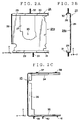
- Fig. 8A is a plan view of the MD cartridge when viewed from the surface side.
- Fig. 8B is another plan view of the MD cartridge when viewed from the back side.
- the MD cartridge has a structure based on a prescribed standard in which a disk-shaped recording/reproducing medium 4 supported by a circular clamping region 3 is housed in a cartridge case 2 with resin-molded square shells superposed on each other.
- the cartridge case 2 includes, on its back side, a square opening 5 for exposing the one side of the recording/reproducing medium 4 during recording/reproducing, a sliding shutter for protecting the recording/reproducing medium 4 by covering the opening 5 during the other period than the recording/reproducing, a circular supporting hole 7 for rotatably supporting the clamping region 3 and positioning holes 8 and 9 for positioning the MD cartridge 1 at a prescribed recording/reproducing position in a recording/reproducing apparatus.
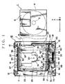
- Fig. 1 is a plan view of the cartridge transporting mechanism 10 which is applied to a recording/reproducing apparatus using an MD cartridge 1.
- fixing members 12 -15 having oscillation-proofing structure for fixing the cartridge transporting apparatus are attached at four positions of the bottom of a square hard frame 11.
- a first side plate 16, which is perpendicular to the bottom face of the hard frame 11, is attached to the fixing members 12 and 13, whereas a supporting member 18 for supporting a second side plate 17, which is perpendicular to the bottom face of the hard frame 11, is attached to the fixing members 14 and 15.
- the first and the second side plate 16 and 17 are arranged in parallel in the x-direction.
- a through-hole 19 is made to expose a magnetic head (not shown) for recording/reproducing, and a turn table (not shown) upward in a z-direction.
- the turn table serves to mount the clamping region 3 of the MD cartridge 1 for recording/reproducing and to rotate it.
- the rotary center position of the turn table is indicated by reference numeral 20.
- Projections 21 and 22 are uprighted apart by a prescribed interval therebetween upward from the bottom of the hard frame 11 so that they are adapted to be engaged with the holes for positioning the MD cartridge.
- a driving roller 23 is provided which is perpendicular to the first and the second side plate 16 and 17.
- the driving roller 23 is formed in a shape of circular cylinder with a metallic rotary shaft which is covered with hard rubber having a friction resistance on its circumferencial face.
- the driving roller 23 is rotatably supported at both ends of the rotary shaft.
- the driving roller 23 is arranged on the second side plate 17.
- the driving roller is designed at a length which is brought into contact with the slide shatter 6 when the MD cartridge 1 is transported.
- a square cartridge holder 24 is arranged above the hard frame 11 between the first and the second side plate 16 and 17, a square cartridge holder 24 is arranged.
- a steering member 25 is arranged between the outer wall of the cartridge 24 and the inner walls of the first and the second side plate 16 and 17.
- a through-hole 27 is made to expose the turn table in such a manner that it overlaps the through-hole 27 for exposing the turn table.
- both sides of the bottom wall 26 in the y-direction as seen from the side view of Fig.
- the cartridge holder 24 has side walls 28 and 29 each having a prescribed height and visors 30 and 31 attached to upper ends the side walls 28 and 29 inwardly.
- the side walls 28, 29 and visors 30, 31 are integrally molded to the bottom wall 26 by the technique such as bending.
- the cartridge holder 24 has engagement projections 32 and 33 oriented outwardly in the y-direction at the prescribed positions of the side walls 28 and 29.
- a spring plate SP is attached to the side wall 28 so that it is elastically engaged with the shatter 6 of the MD cartridge 1.
- the shatter 6 can be opened in accordance with the carry-in operation of the MD cartridge 1.
- the MD cartridge 1 is adapted to be inserted horizontally from an inlet/outlet position on the side of the driving roller 23 into a square gap 24a defined by the bottom wall 26, side walls 28, 29 and visors 30, 31.
- the MD cartridge 1 is adapted to be inserted in such a fashion that its bottom face (rear face) is oriented toward the driving roller 23.
- the steering member 25 includes a first arm 34 which intervenes between the first side plate 16 and the side wall 28 of the cartridge holder 24, a second arm 35 which intervenes between the second side plate 17 and the side wall of the cartridge holder 24, and a coupling member 36 coupling these first and second arms 34 and 35 with each other.
- the first and the second arm 34 and 35 have a plurality of engagement projections 37, 38, 39, 40 and 41 which protrude outwardly in the y-direction at the prescribed positions of the arms 34 and 35.
- the second arm 35 of the steering member 25 has a pair of guiding projections 43 and 44 which protrude from the bottom thereof.
- the second arm 35 has a slanted guiding hole 42 slanted on the skew for the x-direction and y-direction.
- the second side plate 17 has lengthy engagement holes 45, 46 and 47 in the x-direction and a guide hole 48 in the z-direction.
- the supporting member 18 has guide members 49 and 50 for guiding the steering member 25 back and forth in the x-direction while they are engaged with the guiding protrusions 43 and 44.
- the engagement projections 39, 40 and 41 of the second arm 35 are fit in the engagement holes 45, 46 and 47.
- the engagement projection 33 of the cartridge holder 24 is fit in the hole formed when the slanted guide hole 42 of the second arm 35 and the guide hole 48 of the second side plate 17 overlap.
- the cartridge holder 24 and the second arm 35 of the steering member 25 are combined with the second side plate 17.
- the guide hole 48 has a length in the z-direction which is equal to the clamping distance along which the cartridge holder 24 is moved to the recording/reproducing position during loading described later.
- the slanted guide hole 42 is designed so that the engagement projection 33 is movable in the guide hole 48.
- the first arm 34 of the steering member 25 also has a slanted guide hole similar to the slanted guide hole of the second arm 35.
- the first side plate 16 also has engagement holes and a guide hole similar to the engagement holes 45 - 47 and guide hole 48 of the second side plate 17.
- the cartridge holder 24 and first arm 34 of the steering member 25 are combined with the first side plate 16 in such a manner that the engagement projections 32, 37 and 38 are fit in the slanted guide hole, engagement hole and guide hole on the side of the first side plate 16 and first arm 34. Therefore, when the steering member 25 moves in the x-direction, the cartridge holder 24 can move with no slant nor rattle.
- a rack member 51 is arranged on the outside of the second side plate 17.
- the rack member 51 has elliptical eccentric holes 52, 53, gear 54 and a contact portion 55 which extends to the inside of the cartridge holder 24.
- the engagement projections 39 and 40 are adapted to fit in the eccentric holes 52 and 53.
- the eccentric holes 52 and 53 of the rack member 51 are designed to have a length in the x-direction so that the moving distance in the x-direction of the rack member 51 in the state where the engagement projections 39, 40 have been fit in the engagement holes is approximately equal to the radius of the driving roller 23 for transporting the cartridge 1.
- a gear plate 70 is arranged on the outside of the rack member 51.
- the gear plate 70 has a gear portion 71 and engagement holes 72, 73.
- the engagement projections 39 and 40 are adapted to fit in the engagement holes 72 and 73 so that the gear plate 70 is secured to the tip of the engagement protrusions 39 and 40.
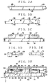
- Fig. 3 is a side view of the state where the cartridge holder 24, steering member 25, second side plate 17, rack member 51 and a gear plate 70 have been assembled.
- the gear portion 54 of the rack member 51 is designed to have a length of the radius of the driving roller 23 plus the length of the slanted guide hole 42 in the x-direction, over which the rack member 51 can move.
- the gear portion 71 of the gear plate 70 is designed to have a length of the slanted guide hole 42 over which the steering member 25 can move.
- the engagement projection 33 of the cartridge holder 24 resides at the top of the slanted guide hole 42 in the z-direction and the cartridge holder 24 resides to be able to house the cartridge 1 which is transported by the rotation of the driving roller 23.
- the rack member 51 is in a state where the engagement protrusions 39 and 40 of the steering member 25 are in contact with the leftmost positions of the the eccentric holes 52 and 53, respectively.
- the gear 69 is not still engaged with the gear portion 54 of the rack member 51.
- the gear 69 will be engaged with the gear 54.
- the contact portion 55 of the rack member 51 resides at the position slightly shorter than the length of the cartridge from the center of the driving roller 23.
- the gear plate 70 has a gear portion 71 extending from the position where it is engaged with the gear 69 after the rack 51 moves in the x-direction to bring the engagement protrusions 39, 40 into contact with the rightmost ends of the eccentric holes 52, 53
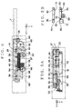
- FIG. 4 is a side view of the holder transporting mechanism seen from the side of the second side plate.
- the holder transporting mechanism is supported by a supporting member 18 and is provided with a driving motor 56 and plural worm gears 57, 58 and gears 59 - 69.
- the gear 59 is engaged with the worm gear 57 coupled with the driving shaft of the driving motor 56.
- the gear 61 is engaged with the small-diameter gear 60 integrated with the gear 59.
- the gear 63 is engaged with the small-diameter gear 62 integrated with the gear 61.
- the gear 64 fixed to the rotary shaft of the driving roller 23 is engaged with the gear 63.
- the gear 65 is engaged with the worm gear 57.
- the gear 66 is engaged with the worm gear 58 integrated with the gear 65.
- the gear 68 is engaged with the small-diameter gear 67 integrated with the gear 66.
- the small-diameter gear 69 integrated with the gear 68 is located at a position where it is not engaged with the gear 54 of the rack member 51 when the rack 51 moves rightmost under control by the eccentric holes 52 and 53.
- FIGs. 5A, 6A and 7A are side views of the cartridge transporting apparatus when seen from the side of the rack 51 in which the holder transporting mechanism except the gear 69 is not shown.
- the operation will be explained typically of the cartridge holder 24, steering member 25 and rack member 51 for the second side plate 17.
- the operation will be not explained about the cartridge holder 24, steering member 25 and rack member 25 and rack member for the first side plate 16.
- Figs. 5B, 6B and 7B show a relationship among the gear plate 70, rack member 51 and gear 69.
- the rack member 51 moves rightward according to the displacement between the engagement protrusions 39, 40 and the elliptical eccentric holes 52, 53.
- the engagement protrusions 33, 39, 40 and 41 as shown in Figs. 3A - 3C are limited by the engagement holes 45, 46 and 47, slanted guide hole 42 and guide hole 48.
- the cartridge holder 24 and steering member 25 are at rest at a rightmost position for the first side plate 17.
- the gear 54 of the rack member 51 is not engaged with the gear 69.
- the engagement projection 33 is moved in the direction defined by the slanted hole 42 and guide hole 48, i.e. z-direction.
- the cartridge holder 24 is forcibly descended toward the bottom wall of the hard plate 11.
- the rear end of the cartridge 1 in the insertion direction remains in contact with the driving roller 23.
- this does not hinder the descend of the cartridge in the z-direction since the driving roller 23 is rotating counterclockwise.
- the rear end of the cartridge 1 in the insertion direction descends being in contact with the driving roller 23.
- the cartridge holder 24 descends so that the clamping region 3 of the cartridge 1 is loaded on the turn table so as to be aligned with the rotary center position 20.
- the cartridge 1 is loaded surely and accurately in a prescribed recording/reproducing position since the positioning protrusions 21 and 22 uprighted from the hard frame 11 are fit in the positioning holes 8 and 9.
- the gear 69 further rotates so that the rack member 51 moves rightwards. Then, the cartridge 1 in the cartridge holder 24 is extruded by the contact portion 55 of the rack member 51. As a result, as shown in Fig. 6A, the rear end of the cartridge 1 in the insertion direction is brought into contact with the driving roller 23 as shown in Fig. 6A. Thus, the transportation of the cartridge 1 is started in the x-direction.
- the gear 69 leaves from the gear portion 54 of the rack member 51.
- the driving of the driving motor 56 is stopped.
- the contact area between the cartridge 1 and driving roller 23 is increased, thereby improving the reliability of transportation. Further, the increase in the contact area between the cartridge 1 and driving roller 23 greatly reduces the aberration of the contact face of the driving roller 23. Since the cartridge 1 can be transported by the driving roller 23 not being in contact with the sliding shutter 6, an accident that the sliding shutter 6 is inadvertently opened during transportation to injure the recording/reproducing medium 4 can be prevented.
- the cartridge can be transported to a prescribed recording/reproducing position surely and accurately.
Landscapes
- Feeding And Guiding Record Carriers (AREA)
Applications Claiming Priority (2)
| Application Number | Priority Date | Filing Date | Title |
|---|---|---|---|
| JP2197799 | 1999-01-29 | ||
| JP02197799A JP3822760B2 (ja) | 1999-01-29 | 1999-01-29 | カートリッジ搬送装置 |
Publications (2)
| Publication Number | Publication Date |
|---|---|
| EP1024486A2 true EP1024486A2 (fr) | 2000-08-02 |
| EP1024486A3 EP1024486A3 (fr) | 2000-12-06 |
Family
ID=12070097
Family Applications (1)
| Application Number | Title | Priority Date | Filing Date |
|---|---|---|---|
| EP00101704A Withdrawn EP1024486A3 (fr) | 1999-01-29 | 2000-01-27 | Appareil de transport de cassette |
Country Status (3)
| Country | Link |
|---|---|
| US (1) | US6388973B1 (fr) |
| EP (1) | EP1024486A3 (fr) |
| JP (1) | JP3822760B2 (fr) |
Families Citing this family (2)
| Publication number | Priority date | Publication date | Assignee | Title |
|---|---|---|---|---|
| US6526018B1 (en) * | 1999-12-08 | 2003-02-25 | Matsushita Electric Industrial Co., Ltd. | Disk cartridge |
| JP2007012104A (ja) * | 2005-06-28 | 2007-01-18 | Mitsumi Electric Co Ltd | 記録再生装置およびクラッチ部材 |
Family Cites Families (11)
| Publication number | Priority date | Publication date | Assignee | Title |
|---|---|---|---|---|
| DE3672000D1 (de) * | 1985-08-10 | 1990-07-19 | Sanyo Electric Co | Frontladevorrichtung fuer plattengeraet. |
| US5146069A (en) * | 1988-09-19 | 1992-09-08 | Fuji Photo Film Co., Ltd. | Device for loading and unloading a memory cartridge using a sliding member |
| JPH0722006A (ja) | 1993-07-06 | 1995-01-24 | Yuasa Corp | プリント基板への電池配置方法 |
| US5537378A (en) * | 1993-08-25 | 1996-07-16 | Clarion Co., Ltd. | Data processing device with controlled insertion of recording media |
| JPH07226006A (ja) * | 1994-02-08 | 1995-08-22 | Matsushita Electric Ind Co Ltd | ディスク記録再生装置 |
| JP3404912B2 (ja) * | 1994-09-19 | 2003-05-12 | 松下電器産業株式会社 | ローディング装置 |
| JP3215290B2 (ja) * | 1995-05-22 | 2001-10-02 | シャープ株式会社 | ディスク記録再生装置 |
| JP3514549B2 (ja) * | 1995-05-26 | 2004-03-31 | アルパイン株式会社 | 記録媒体の搬送装置 |
| JP3410282B2 (ja) * | 1996-03-19 | 2003-05-26 | パイオニア株式会社 | ディスクドライブ装置 |
| JP3424227B2 (ja) * | 1997-06-04 | 2003-07-07 | 日本ビクター株式会社 | ミニディスク及びコンパクトディスクの兼用ディスクプレーヤ |
| JP2000100039A (ja) * | 1998-09-28 | 2000-04-07 | Pioneer Electronic Corp | カートリッジ搬送装置 |
-
1999
- 1999-01-29 JP JP02197799A patent/JP3822760B2/ja not_active Expired - Fee Related
-
2000
- 2000-01-27 EP EP00101704A patent/EP1024486A3/fr not_active Withdrawn
- 2000-01-28 US US09/493,286 patent/US6388973B1/en not_active Expired - Fee Related
Also Published As
| Publication number | Publication date |
|---|---|
| EP1024486A3 (fr) | 2000-12-06 |
| JP3822760B2 (ja) | 2006-09-20 |
| JP2000222805A (ja) | 2000-08-11 |
| US6388973B1 (en) | 2002-05-14 |
Similar Documents
| Publication | Publication Date | Title |
|---|---|---|
| JP2850431B2 (ja) | 記録媒体駆動装置及びこれを備えた電子機器 | |
| US6480360B1 (en) | Method of accessing a disk-like recording medium in a disk cartridge | |
| US6388973B1 (en) | Cartridge transporting apparatus | |
| EP1016081B1 (fr) | Mecanisme de fixation de disque pour appareil a disques | |
| US20010021156A1 (en) | Disk device having disk transferring mechanism capable of shortening disk replacement time--in its place | |
| JP2517896B2 (ja) | ヘッド送り装置 | |
| JP2005116029A (ja) | ディスクプレーヤのディスク搬送機構 | |
| JP2000100039A (ja) | カートリッジ搬送装置 | |
| US6556373B1 (en) | Disk apparatus, method of accessing head thereof to disk-like recording medium, and method of retracting the same | |
| EP1024485A2 (fr) | Appareil de transport de cassette | |
| EP1465190A2 (fr) | Dispositif d'enregistrement magnétique du type carte | |
| US4853806A (en) | Apparatus for regulating the force rendered to a magnetic disc by a magnetic head in a rotary magnetic disc device | |
| JP2551145Y2 (ja) | ディスク駆動装置 | |
| JP2001143419A (ja) | ディスクドライブ装置 | |
| JP2597577Y2 (ja) | ディスク装置 | |
| CN1954378A (zh) | 光盘装置 | |
| JP2001143418A (ja) | ディスクドライブ装置 | |
| JP2001093217A (ja) | ディスクドライブ装置 | |
| JP2001093270A (ja) | カートリッジ型記録媒体のチャッキング方式、カートリッジ型記録媒体及びこれを用いるディスクドライブ装置 | |
| JP2001143429A (ja) | ディスクカートリッジ | |
| JP2001143428A (ja) | カートリッジ型記録媒体 | |
| JP2001143410A (ja) | ディスクドライブ装置 | |
| JP2001143417A (ja) | ディスクドライブ装置 | |
| JP2001093256A (ja) | カートリッジ型記録媒体及びこれを用いるドライブ装置 | |
| JP2001093216A (ja) | ディスクドライブ装置 |
Legal Events
| Date | Code | Title | Description |
|---|---|---|---|
| PUAI | Public reference made under article 153(3) epc to a published international application that has entered the european phase |
Free format text: ORIGINAL CODE: 0009012 |
|
| AK | Designated contracting states |
Kind code of ref document: A2 Designated state(s): DE FR GB |
|
| AX | Request for extension of the european patent |
Free format text: AL;LT;LV;MK;RO;SI |
|
| PUAL | Search report despatched |
Free format text: ORIGINAL CODE: 0009013 |
|
| AK | Designated contracting states |
Kind code of ref document: A3 Designated state(s): AT BE CH CY DE DK ES FI FR GB GR IE IT LI LU MC NL PT SE |
|
| AX | Request for extension of the european patent |
Free format text: AL;LT;LV;MK;RO;SI |
|
| RIC1 | Information provided on ipc code assigned before grant |
Free format text: 7G 11B 17/04 A, 7G 11B 23/03 B, 7G 11B 33/08 B |
|
| 17P | Request for examination filed |
Effective date: 20001117 |
|
| AKX | Designation fees paid |
Free format text: DE FR GB |
|
| STAA | Information on the status of an ep patent application or granted ep patent |
Free format text: STATUS: THE APPLICATION IS DEEMED TO BE WITHDRAWN |
|
| 18D | Application deemed to be withdrawn |
Effective date: 20060419 |