EP1024372B1 - Dispositif pour détecter la position - Google Patents
Dispositif pour détecter la position Download PDFInfo
- Publication number
- EP1024372B1 EP1024372B1 EP00100975A EP00100975A EP1024372B1 EP 1024372 B1 EP1024372 B1 EP 1024372B1 EP 00100975 A EP00100975 A EP 00100975A EP 00100975 A EP00100975 A EP 00100975A EP 1024372 B1 EP1024372 B1 EP 1024372B1
- Authority
- EP
- European Patent Office
- Prior art keywords
- acoustic signal
- signal line
- signal
- evaluation unit
- moving object
- Prior art date
- Legal status (The legal status is an assumption and is not a legal conclusion. Google has not performed a legal analysis and makes no representation as to the accuracy of the status listed.)
- Expired - Lifetime
Links
Images

Classifications
-
- B—PERFORMING OPERATIONS; TRANSPORTING
- B66—HOISTING; LIFTING; HAULING
- B66B—ELEVATORS; ESCALATORS OR MOVING WALKWAYS
- B66B1/00—Control systems of elevators in general
- B66B1/34—Details, e.g. call counting devices, data transmission from car to control system, devices giving information to the control system
- B66B1/3492—Position or motion detectors or driving means for the detector
-
- G—PHYSICS
- G01—MEASURING; TESTING
- G01S—RADIO DIRECTION-FINDING; RADIO NAVIGATION; DETERMINING DISTANCE OR VELOCITY BY USE OF RADIO WAVES; LOCATING OR PRESENCE-DETECTING BY USE OF THE REFLECTION OR RERADIATION OF RADIO WAVES; ANALOGOUS ARRANGEMENTS USING OTHER WAVES
- G01S11/00—Systems for determining distance or velocity not using reflection or reradiation
- G01S11/14—Systems for determining distance or velocity not using reflection or reradiation using ultrasonic, sonic, or infrasonic waves
Definitions
- the invention relates to a device for detecting a position along a predetermined distance moving object after the Preamble of claim 1.
- Such a device is known from EP-A-0 694 792 Position detection of a moving object known, the one Acoustic signal conductors extending along a travel path with predetermined uniform sound propagation speed as well as one with a Signal generator connected, located on the movable object Signal coupler for coupling a sound signal into the sound signal conductor having.
- a Signal generator located on the movable object Signal coupler for coupling a sound signal into the sound signal conductor having.
- the sound signal conductor Signal decouplers arranged, which are each connected to a counter, the two counters being clocked by a clock generator and with a Subtractors for the output signals of the two counters are connected.
- the output signal of the subtractor is a measure of the transit time difference Coupled sound signal from the coupling point to the Signal decouplers can be processed by an evaluation unit to form a signal, for the current position of the moving object on the Travel is representative, the signal coupler with a Signal separation time works that is greater than the sound propagation time from one end of the path to the other.
- the evaluation unit By means of the evaluation unit and one implemented in it Calculation algorithm is the measured transit times from the sound coupler a position value is assigned to the signal decouplers. Especially in elevator construction the evaluation unit is calibrated by the leveling point of each Floor assigned the result of the calculation algorithm in this point and the elevator position is associated with this numerical value. by virtue of of temperature-related changes in building and / or sound signal conductor length or by changing the speed of sound in the However, the sound signal conductor shifts due to temperature and diffusion effects the assignment between the leveling point and the one resulting from the calibration assigned numerical value.
- the object of the invention is a device for position detection an object moving along a predetermined distance the preamble of claim 1, with which it is possible to create simple and precisely predetermined positions of the movable object approach a long distance.
- the device shown for position detection in particular can be used to detect the position of an elevator cage includes one Sound signal conductor 1, for example a steel rail or in particular a wire, which extends along a predetermined travel path, along the one movable object 2, such as an elevator basket, is movable back and forth.
- the sound signal conductor 1 with a predetermined, more uniform Sound propagation speed is damping at both ends Clamping or bracket 3 clamped clamped or held.
- the movable object 2 carries a signal coupler 4, which with a signal generator 5, such as an oscillator, via a Signal matching circuit 4 'is connected.
- the signal coupler 4 the works particularly inductively, couples a sound signal that periodically from the signal generator 5 received synchronization pulses S, in the Sound signal conductor 1 a.
- the synchronization pulses S have a cycle time greater than the duration of the sound signal from one end of the Sound signal conductor 1 to others.
- the signal coupler couples 4 additional pulses M, and a large number of additional pulses M during each cycle time Synchronization pulses S.
- the cycle time of the additional pulses M is such that one for braking and for moving to an exact position the object 2 required distance resolution in the direction of the travel is achieved.
- the synchronization pulses S are marked, i.e. of the Additional pulses M can be distinguished by evaluation.
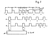
- the marking can for example, in that their cycle time is a corresponding one Is a multiple of the cycle time of the additional pulses M and they with respect to Additional pulses M additionally, for example by half a cycle time, are delayed, cf. the pulse train of the first generated by the signal generator 5 Row of Fig. 2. Then follows a synchronization pulse S one predetermined number of additional pulses M.
- the marking can also be done in a different way are, so the synchronization pulses S of the Additional pulses M through modulation, pulse width, pulse height or the like. differ.
- synchronization and additional pulses S, M to be coupled in can be short electromagnetic impulses, such as simple pulses or pulse sequences or periodic frequency shift keying.
- a signal decoupler 6 arranged at the ends of the sound signal conductor 1 .
- This is preferably a piezoelectric signal decoupler 6, however, can also be inductive or capacitive working.
- Each signal decoupler 6 has a signal matching circuit 7 connected, the output lines each lead to a counter 8.
- Both Counters 8 are clocked by a clock generator 9, an oscillator.
- the cycle time of the clock generator 9 is considerably shorter than the running time of the sound from one end of the sound signal conductor 1 to the other and corresponding to the desired measurement path resolution selected.
- the outputs of the counters 8 are fed to a subtractor 10, which is the difference between the Output signals of the counter 8 forms and an evaluation unit 11, such as one Microprocessor feeds where the output signal of the subtractor 10th is evaluated.
- the evaluation for position detection is primarily carried out in relation to the Additional signals M, however, the synchronization pulses S be evaluated in this regard, above all, but not only, if the mth additional pulse is marked, so as Serve synchronization pulse S.
- the movable object 2 is in the middle between the Signal decouplers 6, the outputs of the counters 8 are the same and their difference zero.
- Item 2 is located (for a vertical route) above the Middle, is the output of the upper signal decoupler 6 connected counter 8 smaller than that of the other.
- From the from Subtractor 10 determined transit time difference of the related Additional pulses M in the sound signal conductor 1 and the known one Speed of sound in this gives the distance of the moving Object 2 from the center. Because when the moving Item 2 would be below the center, the difference is another Is also known whether the moving Item 2 is above or below the center, i.e. with that is the exact position of the movable object 2 can be calculated.
- Such a thing Evaluation unit 11 can generate a digital or analog position signal used for succession control.
- a watchdog 12 (monitoring circuit) of the evaluation unit 11 can be used for simple monitoring of the measuring section at a time constant Coupling of the coupling signal can be used.
- the difference determined by the subtractor 10 exceeds one predetermined value to which the watchdog 12 responds by a corresponding warning signal or the like. trigger.
- the sensors 13 are preferably in pairs (at least one pair, which also depends in particular on the length of the sound signal conductor 1) each arranged the same distance from the center of the sound signal conductor 1.
- Errors such as those caused by changes in the height of a building or by Change in the speed of sound in the sound signal conductor 1 by temperature and / or Diffusion effects also have a corresponding effect Calibration points of the sensors 13 and are recognized there because of the Pulse the absolute position is always known and is accordingly from the Difference between the existing calibration and the measurement at Time of occurrence of the pulse of the errors at this point of the Travel path on which the respective sensor 13 is located. With the help of so known errors in at least two places can be at least one straight line be determined according to the calibration points by the Evaluation unit 11 can be recalibrated.
- the sound signal conductor 1 is not too long, two are sufficient Sensors 13, since the errors that occur in a first approximation are linear Dependence on the distance from a reference point. For larger ones however, lengths more than two sensors 13 are appropriate, their Error deviations are used to determine the coefficients of a polynomial to determine a predetermined degree, according to which the Recalibration of the calibration points, including those by the Sensors 13 formed, is made.
- This continuous recalibration eliminates the errors due to change in the speed of sound in the sound signal conductor 1 on the real length of the measuring path is compensated. This enables use a simple sound signal conductor 1 in the form of a wire.
- the speed of sound is in a sound signal conductor 1 made of steel at about 5300 m / s.
- a temporal resolution of 188 ns, which is one Clock frequency of 5.3 MHz is necessary, the spatial resolution of the Measuring distance at 1 mm.
- the former can also be triggered by the evaluation unit 11 in order to Coupling sound signals into the sound signal conductor 1. Instead it is also possible that the signal coupler 4 the evaluation unit 11 via a electrical signal triggers the timing of the coupling of a Sound signal in the sound signal conductor 1 for evaluation by the To define evaluation unit 11.
Claims (11)
- Dispositif pour la détection de la position d'un objet (2) mobile le long d'une voie de circulation prédéterminée, comprenant un conducteur de signaux sonores (1) qui s'étend le long de la voie de circulation et qui présente une vitesse de propagation des sons prédéterminée, constante, ainsi qu'un injecteur de signaux (4) relié à un émetteur de signaux (5) qui se trouve sur l'objet mobile (2), et est destiné à injecter un signal sonore rythmé dans le conducteur de signaux sonores (1), cependant qu'à au moins une extrémité du conducteur de signaux sonores (1), est disposé un extracteur de signaux (6) qui est relié à une unité d'analyse (11) destinée à produire un signal représentatif de la position momentanée de l'objet mobile (2) sur la voie de circulation, caractérisé en ce qu'au moins un capteur (13) qui peut être actionné par le passage de l'objet mobile (2) est disposé à une distance prédéterminée du milieu du conducteur de signaux sonores (1) et accouplé l'unité d'analyse (11), laquelle compense des points d'étalonnage sur la longueur de la voie de circulation pour l'élimination des erreurs en appliquant un polynôme d'erreur dont les coefficients sont dérivés d'erreurs, l'erreur liée à un trajet déterminé de la voie de circulation étant obtenue par analyse de l'impulsion émise par le capteur (13) associé au trajet lors du passage de l'objet mobile (2).
- Dispositif selon la revendication 1, caractérisé en ce que le polynôme d'erreur est une droite.
- Dispositif selon la revendication 1, caractérisé en ce que le polynôme d'erreur est un polynôme d'ordre plus élevé.
- Dispositif selon l'une des revendications 1 à 3, caractérisé en ce qu'il est prévu au moins deux capteurs (13) qui sont de préférence disposés par paires symétriquement par rapport au milieu du conducteur de signaux sonores (1)
- Dispositif selon l'une des revendications 1 à 4, caractérisé en ce que le conducteur de signaux sonores (1) est un fil métallique.
- Dispositif selon l'une des revendications 1 à 5, caractérisé en ce qu'il est
prévu deux extracteurs de signaux (6), munis chacun d'un compteur (8) placé en aval, les deux compteurs (8) étant rythmés au-moyen d'un-rythmeur (9) et étant relié à un soustracteur (10) agissant sur les signaux de sortie des deux compteurs (8). - Dispositif selon la revendication 6, caractérisé en ce que le rythmeur (9) prévu pour les compteurs (8) travaille avec une fréquence minimale nécessaire pour assurer une résolution prévue du trajet de mesure.
- Dispositif selon l'une des revendications 1 à 7, caractérisé en ce que les extracteurs de signaux (6) sont des extracteurs capacitifs, inductifs ou, en particulier, piézoélectriques.
- Dispositif selon l'une des revendications 6 à 8, caractérisé en ce que l'unité d'analyse (11) comprend un circuit de surveillance (12) qui déclenche un signal avertisseur lorsque la différence constatée par le soustracteur (10) devient supérieure à une valeur prédéterminée.
- Dispositif selon l'une des revendications 1 à 9, caractérisé en ce que l'objet mobile (2) est une cabine d'ascenseur.
- Dispositif selon l'une des revendications 1 à 10, caractérisé en ce qu'à chaque extrémité du conducteur de signaux sonores (1) est associé un extracteur de signaux (6), les extracteurs de signaux étant couplés à l'unité d'analyse (11).
Applications Claiming Priority (2)
| Application Number | Priority Date | Filing Date | Title |
|---|---|---|---|
| DE19903643 | 1999-01-29 | ||
| DE19903643A DE19903643A1 (de) | 1999-01-29 | 1999-01-29 | Einrichtung zur Positionserfassung |
Publications (2)
| Publication Number | Publication Date |
|---|---|
| EP1024372A1 EP1024372A1 (fr) | 2000-08-02 |
| EP1024372B1 true EP1024372B1 (fr) | 2002-10-02 |
Family
ID=7895844
Family Applications (1)
| Application Number | Title | Priority Date | Filing Date |
|---|---|---|---|
| EP00100975A Expired - Lifetime EP1024372B1 (fr) | 1999-01-29 | 2000-01-19 | Dispositif pour détecter la position |
Country Status (7)
| Country | Link |
|---|---|
| US (1) | US6311803B1 (fr) |
| EP (1) | EP1024372B1 (fr) |
| JP (1) | JP3485851B2 (fr) |
| CN (1) | CN1264047A (fr) |
| BR (1) | BR0000216A (fr) |
| CA (1) | CA2296656C (fr) |
| DE (2) | DE19903643A1 (fr) |
Families Citing this family (17)
| Publication number | Priority date | Publication date | Assignee | Title |
|---|---|---|---|---|
| ES2352340T3 (es) * | 1997-07-05 | 2011-02-17 | Hudson-Sharp Machine Company | Aparato para la aplicación de cierres resellables sobre una banda de película. |
| US6570817B2 (en) * | 1999-01-29 | 2003-05-27 | K. A. Schmersal Gmbh & Co. | Apparatus for detecting position |
| DE10129044C2 (de) * | 2001-06-15 | 2003-07-24 | Schmersal K A Gmbh & Co | Einrichtung zur Positionserfassung |
| DE10133171C1 (de) * | 2001-07-07 | 2002-12-05 | Schmersal K A Gmbh & Co | Verfahren und Einrichtung zur Positionserfassung |
| US7204347B2 (en) * | 2001-11-15 | 2007-04-17 | Otis Elevator Company | Arrhythmic pulse sequence for sonic distance measurement |
| DE10156043B4 (de) * | 2001-11-15 | 2006-03-02 | Otis Elevator Co., Farmington | Positionsermittlungsvorrichtung |
| JP4422035B2 (ja) * | 2003-02-03 | 2010-02-24 | オーチス エレベータ カンパニー | 受動超音波rfidエレベータ位置決め基準システム |
| ITBO20030141A1 (it) * | 2003-03-13 | 2004-09-14 | Jobs Spa | Dispositivo di controllo della posizione di un mandrino |
| DE10324532B4 (de) * | 2003-05-28 | 2005-07-21 | Dorma Gmbh + Co. Kg | Messsystem zur Bestimmung einer absoluten Position eines sich entlang einer Führungsschiene bewegenden Elementes, Horizontalschiebewand und Element für eine Horizontalschiebewand |
| US7434988B1 (en) | 2006-05-17 | 2008-10-14 | Enertechnix, Inc. | Low pressure acoustic pyrometer signal generator |
| CN101452265B (zh) * | 2007-12-04 | 2011-12-21 | 丁晓跃 | 实时在线自动校准方法和装置 |
| US8699200B2 (en) * | 2010-02-05 | 2014-04-15 | Honeywell International Inc. | Secure non-contact switch |
| US8456792B2 (en) * | 2010-02-05 | 2013-06-04 | Honeywell International Inc. | Secure non-contact switch |
| DE102013012761B3 (de) * | 2013-07-31 | 2014-12-24 | Georg-Simon-Ohm Hochschule für angewandte Wissenschaften Fachhochschule Nürnberg | Vorrichtung zur Bestimmung der Position einer Signalquelle |
| CN105173935B (zh) * | 2015-08-06 | 2017-04-05 | 日立电梯(中国)有限公司 | 电梯平层位置的控制装置及方法 |
| AU2018275606B2 (en) * | 2017-06-02 | 2021-05-20 | Inventio Ag | Floor position detection device of a lift installation and method for generating a floor signal |
| GB2574644B (en) * | 2018-06-13 | 2022-09-07 | Avire Ltd | A location system, method, and calibration method |
Family Cites Families (24)
| Publication number | Priority date | Publication date | Assignee | Title |
|---|---|---|---|---|
| DE965203C (de) | 1954-06-22 | 1957-06-06 | Siemens Ag | Verfahren und Einrichtung zur Aufzeichnung von Impulsfolgen |
| NO130133B (fr) | 1969-05-28 | 1974-07-08 | Krupp Gmbh | |
| GB1480779A (en) * | 1974-10-04 | 1977-07-27 | Coal Ind | Apparatus for determining the position of an object |
| US4035762A (en) | 1974-11-04 | 1977-07-12 | The Charles Stark Draper Laboratory, Inc. | Position sensing readout |
| US4012588A (en) * | 1975-08-29 | 1977-03-15 | Science Accessories Corporation | Position determining apparatus and transducer therefor |
| DE2610127A1 (de) | 1976-03-11 | 1977-09-22 | Roland Dipl Ing Kissling | Vorrichtung zur absolutwertmessung von bewegungsstrecken an maschinen |
| BR7901179A (pt) * | 1978-02-28 | 1979-10-09 | Yokogawa Electric Works Ltd | Dispositivo de deteccao de posicao deslocada |
| JPS54155561A (en) * | 1978-05-29 | 1979-12-07 | Mitsubishi Electric Corp | Position detector for elevator |
| JPS5699181A (en) * | 1980-01-07 | 1981-08-10 | Mitsubishi Electric Corp | Detector for location of elevator |
| FR2475769A1 (fr) * | 1980-02-12 | 1981-08-14 | Framatome Sa | Dispositif acoustique de surveillance d'une installation industrielle |
| US4375057A (en) * | 1980-12-10 | 1983-02-22 | Otis Elevator Company | Position sensor |
| JPS58156872A (ja) | 1982-03-15 | 1983-09-17 | Kazuo Okada | 超音波距離測定装置 |
| US4494224A (en) * | 1982-07-16 | 1985-01-15 | Morrell David J | Pipe measuring method and apparatus |
| JPS5937459A (ja) | 1982-08-27 | 1984-02-29 | Automob Antipollut & Saf Res Center | 超音波による物体検出装置 |
| JPS60218087A (ja) | 1984-04-13 | 1985-10-31 | Komatsu Ltd | 超音波パルスによる物体検出方法 |
| DE3608384A1 (de) | 1986-03-13 | 1987-09-17 | F & O Electronic Systems | Verfahren zur messung von wegen, insbesondere zur absoluten messung von kleinen wegen, ueber die laufzeit von impulsen in einem materiellen traegermedium und zugehoerige vorrichtung zur durchfuehrung des verfahrens |
| GB2211046A (en) * | 1987-10-10 | 1989-06-21 | Thames Valley Lift Company Lim | Lift movement monitoring |
| US5223680A (en) * | 1991-05-03 | 1993-06-29 | Otis Elevator Company | Measuring elevator car position using ultrasound |
| US5306882A (en) * | 1991-05-13 | 1994-04-26 | Otis Elevator Company | Measuring elevator hoistway position using audible signals |
| DE4229079A1 (de) | 1992-09-01 | 1994-03-03 | Vega Grieshaber Gmbh & Co | Verfahren und Vorrichtung zur berührungslosen Abstandsmessung |
| US5406200A (en) | 1993-02-18 | 1995-04-11 | Magnetek Controls, Inc. | Method and apparatus for temperature compensation of magnetostrictive position detection |
| JP3628356B2 (ja) * | 1993-09-29 | 2005-03-09 | オーチス エレベータ カンパニー | エレベータかご位置検出装置 |
| DE4426793C1 (de) * | 1994-07-28 | 1995-10-26 | Schmersal K A Gmbh & Co | Einrichtung zur Positionserfassung |
| US5883345A (en) * | 1997-12-23 | 1999-03-16 | Otis Elevator Company | Sonic position measurement system |
-
1999
- 1999-01-29 DE DE19903643A patent/DE19903643A1/de not_active Withdrawn
-
2000
- 2000-01-19 EP EP00100975A patent/EP1024372B1/fr not_active Expired - Lifetime
- 2000-01-19 DE DE50000574T patent/DE50000574D1/de not_active Expired - Fee Related
- 2000-01-20 CA CA002296656A patent/CA2296656C/fr not_active Expired - Fee Related
- 2000-01-20 JP JP2000011363A patent/JP3485851B2/ja not_active Expired - Fee Related
- 2000-01-24 US US09/490,648 patent/US6311803B1/en not_active Expired - Fee Related
- 2000-01-27 CN CN00101684A patent/CN1264047A/zh active Pending
- 2000-01-28 BR BR0000216-0A patent/BR0000216A/pt not_active IP Right Cessation
Also Published As
| Publication number | Publication date |
|---|---|
| CN1264047A (zh) | 2000-08-23 |
| US6311803B1 (en) | 2001-11-06 |
| JP2000221021A (ja) | 2000-08-11 |
| CA2296656A1 (fr) | 2000-07-29 |
| CA2296656C (fr) | 2004-08-31 |
| DE50000574D1 (de) | 2002-11-07 |
| BR0000216A (pt) | 2000-09-26 |
| JP3485851B2 (ja) | 2004-01-13 |
| DE19903643A1 (de) | 2000-08-24 |
| EP1024372A1 (fr) | 2000-08-02 |
Similar Documents
| Publication | Publication Date | Title |
|---|---|---|
| EP1024372B1 (fr) | Dispositif pour détecter la position | |
| EP0694792B1 (fr) | Appareil de détermination de position | |
| EP0987563B1 (fr) | Méthode pour déterminer la distance de séparation d'un objet et un engin déplaçable, en particulier un véhicule motorisé | |
| WO1998043111A1 (fr) | Procede de determination de l'ecart vertical entre un objet et un dispositif a position variable | |
| DE10335133A1 (de) | Vorrichtung und Verfahren zur Erfassung des Wegs eines Zielobjektes | |
| EP1030190B1 (fr) | Dispositif pour détecter la position | |
| DE102008039025B4 (de) | Verfahren zum berührungslosen Messen der Geschwindigkeit und/oder der Länge eines in Längsrichtung bewegten Strangs, insbesondere eines Kabels | |
| DE19903645C2 (de) | Einrichtung zur Positionserfassung | |
| EP3447456A1 (fr) | Appareil de mesure de niveau de remplissage tdr et procédé de fonctionnement d'un appareil de mesure de niveau de remplissage tdr | |
| DE19505509C2 (de) | Verfahren und Einrichtung zum Messen des Volumens eines bewegten Fördergutes | |
| DE4339419A1 (de) | Einrichtungen und Verfahren zum Erkennen von Metallgegenständen | |
| DE19903646C1 (de) | Einrichtung zur Positionserfassung | |
| DE3522809C2 (fr) | ||
| DE3036164C2 (de) | Längenmeßeinrichtung | |
| EP3350056B1 (fr) | Procédé de détermination de la vitesse d'un véhicule roulant sur rails | |
| DE4332461A1 (de) | Verfahren zum Erkennen von liegenden oder beschädigten Flaschen in einer Gruppe von aufrechtstehenden Flaschen und Vorrichtung zur Durchführung des Verfahrens | |
| AT509885B1 (de) | Vorrichtung und verfahren zur münzerkennung | |
| DE4211144A1 (de) | Berührungslose Geschwindigkeitserfassung von Werkstückträgern | |
| DE2402719C3 (de) | Weg- und Geschwindigkeitsmeßeinrichtung für Schienenfahrzeuge | |
| DE10006379C1 (de) | Einrichtung und Verfahren zur Längenmessung | |
| EP3992583B1 (fr) | Capteur de déplacement magnétostrictif | |
| DE3629174C2 (fr) | ||
| DE10154710A1 (de) | Vorrichtung und Verfahren zur Detektion der Position eines Targets | |
| EP0288952B1 (fr) | Procédé et dispositif de mesure de la vitesse de véhicules | |
| DE1616308B2 (de) | Radar-Anordnung zur Abstandsmessung aufeinanderfolgender Fahrzeuge durch Dopplerfrequenzintegration |
Legal Events
| Date | Code | Title | Description |
|---|---|---|---|
| PUAI | Public reference made under article 153(3) epc to a published international application that has entered the european phase |
Free format text: ORIGINAL CODE: 0009012 |
|
| AK | Designated contracting states |
Kind code of ref document: A1 Designated state(s): DE FR GB IT |
|
| AX | Request for extension of the european patent |
Free format text: AL;LT;LV;MK;RO;SI |
|
| 17P | Request for examination filed |
Effective date: 20001205 |
|
| AKX | Designation fees paid |
Free format text: DE FR GB IT |
|
| GRAG | Despatch of communication of intention to grant |
Free format text: ORIGINAL CODE: EPIDOS AGRA |
|
| GRAG | Despatch of communication of intention to grant |
Free format text: ORIGINAL CODE: EPIDOS AGRA |
|
| GRAH | Despatch of communication of intention to grant a patent |
Free format text: ORIGINAL CODE: EPIDOS IGRA |
|
| 17Q | First examination report despatched |
Effective date: 20020403 |
|
| GRAH | Despatch of communication of intention to grant a patent |
Free format text: ORIGINAL CODE: EPIDOS IGRA |
|
| GRAA | (expected) grant |
Free format text: ORIGINAL CODE: 0009210 |
|
| AK | Designated contracting states |
Kind code of ref document: B1 Designated state(s): DE FR GB IT |
|
| REG | Reference to a national code |
Ref country code: GB Ref legal event code: FG4D Free format text: NOT ENGLISH |
|
| GBT | Gb: translation of ep patent filed (gb section 77(6)(a)/1977) |
Effective date: 20021002 |
|
| REF | Corresponds to: |
Ref document number: 50000574 Country of ref document: DE Date of ref document: 20021107 |
|
| ET | Fr: translation filed | ||
| PLBE | No opposition filed within time limit |
Free format text: ORIGINAL CODE: 0009261 |
|
| STAA | Information on the status of an ep patent application or granted ep patent |
Free format text: STATUS: NO OPPOSITION FILED WITHIN TIME LIMIT |
|
| 26N | No opposition filed |
Effective date: 20030703 |
|
| PGFP | Annual fee paid to national office [announced via postgrant information from national office to epo] |
Ref country code: GB Payment date: 20040105 Year of fee payment: 5 |
|
| PGFP | Annual fee paid to national office [announced via postgrant information from national office to epo] |
Ref country code: FR Payment date: 20040109 Year of fee payment: 5 |
|
| PGFP | Annual fee paid to national office [announced via postgrant information from national office to epo] |
Ref country code: DE Payment date: 20040309 Year of fee payment: 5 |
|
| PG25 | Lapsed in a contracting state [announced via postgrant information from national office to epo] |
Ref country code: IT Free format text: LAPSE BECAUSE OF NON-PAYMENT OF DUE FEES Effective date: 20050119 Ref country code: GB Free format text: LAPSE BECAUSE OF NON-PAYMENT OF DUE FEES Effective date: 20050119 |
|
| PG25 | Lapsed in a contracting state [announced via postgrant information from national office to epo] |
Ref country code: DE Free format text: LAPSE BECAUSE OF NON-PAYMENT OF DUE FEES Effective date: 20050802 |
|
| GBPC | Gb: european patent ceased through non-payment of renewal fee |
Effective date: 20050119 |
|
| PG25 | Lapsed in a contracting state [announced via postgrant information from national office to epo] |
Ref country code: FR Free format text: LAPSE BECAUSE OF NON-PAYMENT OF DUE FEES Effective date: 20050930 |
|
| REG | Reference to a national code |
Ref country code: FR Ref legal event code: ST |