EP1024372B1 - Device for position detection - Google Patents
Device for position detection Download PDFInfo
- Publication number
- EP1024372B1 EP1024372B1 EP00100975A EP00100975A EP1024372B1 EP 1024372 B1 EP1024372 B1 EP 1024372B1 EP 00100975 A EP00100975 A EP 00100975A EP 00100975 A EP00100975 A EP 00100975A EP 1024372 B1 EP1024372 B1 EP 1024372B1
- Authority
- EP
- European Patent Office
- Prior art keywords
- acoustic signal
- signal line
- signal
- evaluation unit
- moving object
- Prior art date
- Legal status (The legal status is an assumption and is not a legal conclusion. Google has not performed a legal analysis and makes no representation as to the accuracy of the status listed.)
- Expired - Lifetime
Links
Images

Classifications
-
- B—PERFORMING OPERATIONS; TRANSPORTING
- B66—HOISTING; LIFTING; HAULING
- B66B—ELEVATORS; ESCALATORS OR MOVING WALKWAYS
- B66B1/00—Control systems of elevators in general
- B66B1/34—Details, e.g. call counting devices, data transmission from car to control system, devices giving information to the control system
- B66B1/3492—Position or motion detectors or driving means for the detector
-
- G—PHYSICS
- G01—MEASURING; TESTING
- G01S—RADIO DIRECTION-FINDING; RADIO NAVIGATION; DETERMINING DISTANCE OR VELOCITY BY USE OF RADIO WAVES; LOCATING OR PRESENCE-DETECTING BY USE OF THE REFLECTION OR RERADIATION OF RADIO WAVES; ANALOGOUS ARRANGEMENTS USING OTHER WAVES
- G01S11/00—Systems for determining distance or velocity not using reflection or reradiation
- G01S11/14—Systems for determining distance or velocity not using reflection or reradiation using ultrasonic, sonic, or infrasonic waves
Definitions
- the invention relates to a device for detecting a position along a predetermined distance moving object after the Preamble of claim 1.
- Such a device is known from EP-A-0 694 792 Position detection of a moving object known, the one Acoustic signal conductors extending along a travel path with predetermined uniform sound propagation speed as well as one with a Signal generator connected, located on the movable object Signal coupler for coupling a sound signal into the sound signal conductor having.
- a Signal generator located on the movable object Signal coupler for coupling a sound signal into the sound signal conductor having.
- the sound signal conductor Signal decouplers arranged, which are each connected to a counter, the two counters being clocked by a clock generator and with a Subtractors for the output signals of the two counters are connected.
- the output signal of the subtractor is a measure of the transit time difference Coupled sound signal from the coupling point to the Signal decouplers can be processed by an evaluation unit to form a signal, for the current position of the moving object on the Travel is representative, the signal coupler with a Signal separation time works that is greater than the sound propagation time from one end of the path to the other.
- the evaluation unit By means of the evaluation unit and one implemented in it Calculation algorithm is the measured transit times from the sound coupler a position value is assigned to the signal decouplers. Especially in elevator construction the evaluation unit is calibrated by the leveling point of each Floor assigned the result of the calculation algorithm in this point and the elevator position is associated with this numerical value. by virtue of of temperature-related changes in building and / or sound signal conductor length or by changing the speed of sound in the However, the sound signal conductor shifts due to temperature and diffusion effects the assignment between the leveling point and the one resulting from the calibration assigned numerical value.
- the object of the invention is a device for position detection an object moving along a predetermined distance the preamble of claim 1, with which it is possible to create simple and precisely predetermined positions of the movable object approach a long distance.
- the device shown for position detection in particular can be used to detect the position of an elevator cage includes one Sound signal conductor 1, for example a steel rail or in particular a wire, which extends along a predetermined travel path, along the one movable object 2, such as an elevator basket, is movable back and forth.
- the sound signal conductor 1 with a predetermined, more uniform Sound propagation speed is damping at both ends Clamping or bracket 3 clamped clamped or held.
- the movable object 2 carries a signal coupler 4, which with a signal generator 5, such as an oscillator, via a Signal matching circuit 4 'is connected.
- the signal coupler 4 the works particularly inductively, couples a sound signal that periodically from the signal generator 5 received synchronization pulses S, in the Sound signal conductor 1 a.
- the synchronization pulses S have a cycle time greater than the duration of the sound signal from one end of the Sound signal conductor 1 to others.
- the signal coupler couples 4 additional pulses M, and a large number of additional pulses M during each cycle time Synchronization pulses S.
- the cycle time of the additional pulses M is such that one for braking and for moving to an exact position the object 2 required distance resolution in the direction of the travel is achieved.
- the synchronization pulses S are marked, i.e. of the Additional pulses M can be distinguished by evaluation.
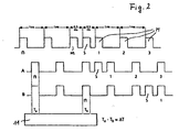
- the marking can for example, in that their cycle time is a corresponding one Is a multiple of the cycle time of the additional pulses M and they with respect to Additional pulses M additionally, for example by half a cycle time, are delayed, cf. the pulse train of the first generated by the signal generator 5 Row of Fig. 2. Then follows a synchronization pulse S one predetermined number of additional pulses M.
- the marking can also be done in a different way are, so the synchronization pulses S of the Additional pulses M through modulation, pulse width, pulse height or the like. differ.
- synchronization and additional pulses S, M to be coupled in can be short electromagnetic impulses, such as simple pulses or pulse sequences or periodic frequency shift keying.
- a signal decoupler 6 arranged at the ends of the sound signal conductor 1 .
- This is preferably a piezoelectric signal decoupler 6, however, can also be inductive or capacitive working.
- Each signal decoupler 6 has a signal matching circuit 7 connected, the output lines each lead to a counter 8.
- Both Counters 8 are clocked by a clock generator 9, an oscillator.
- the cycle time of the clock generator 9 is considerably shorter than the running time of the sound from one end of the sound signal conductor 1 to the other and corresponding to the desired measurement path resolution selected.
- the outputs of the counters 8 are fed to a subtractor 10, which is the difference between the Output signals of the counter 8 forms and an evaluation unit 11, such as one Microprocessor feeds where the output signal of the subtractor 10th is evaluated.
- the evaluation for position detection is primarily carried out in relation to the Additional signals M, however, the synchronization pulses S be evaluated in this regard, above all, but not only, if the mth additional pulse is marked, so as Serve synchronization pulse S.
- the movable object 2 is in the middle between the Signal decouplers 6, the outputs of the counters 8 are the same and their difference zero.
- Item 2 is located (for a vertical route) above the Middle, is the output of the upper signal decoupler 6 connected counter 8 smaller than that of the other.
- From the from Subtractor 10 determined transit time difference of the related Additional pulses M in the sound signal conductor 1 and the known one Speed of sound in this gives the distance of the moving Object 2 from the center. Because when the moving Item 2 would be below the center, the difference is another Is also known whether the moving Item 2 is above or below the center, i.e. with that is the exact position of the movable object 2 can be calculated.
- Such a thing Evaluation unit 11 can generate a digital or analog position signal used for succession control.
- a watchdog 12 (monitoring circuit) of the evaluation unit 11 can be used for simple monitoring of the measuring section at a time constant Coupling of the coupling signal can be used.
- the difference determined by the subtractor 10 exceeds one predetermined value to which the watchdog 12 responds by a corresponding warning signal or the like. trigger.
- the sensors 13 are preferably in pairs (at least one pair, which also depends in particular on the length of the sound signal conductor 1) each arranged the same distance from the center of the sound signal conductor 1.
- Errors such as those caused by changes in the height of a building or by Change in the speed of sound in the sound signal conductor 1 by temperature and / or Diffusion effects also have a corresponding effect Calibration points of the sensors 13 and are recognized there because of the Pulse the absolute position is always known and is accordingly from the Difference between the existing calibration and the measurement at Time of occurrence of the pulse of the errors at this point of the Travel path on which the respective sensor 13 is located. With the help of so known errors in at least two places can be at least one straight line be determined according to the calibration points by the Evaluation unit 11 can be recalibrated.
- the sound signal conductor 1 is not too long, two are sufficient Sensors 13, since the errors that occur in a first approximation are linear Dependence on the distance from a reference point. For larger ones however, lengths more than two sensors 13 are appropriate, their Error deviations are used to determine the coefficients of a polynomial to determine a predetermined degree, according to which the Recalibration of the calibration points, including those by the Sensors 13 formed, is made.
- This continuous recalibration eliminates the errors due to change in the speed of sound in the sound signal conductor 1 on the real length of the measuring path is compensated. This enables use a simple sound signal conductor 1 in the form of a wire.
- the speed of sound is in a sound signal conductor 1 made of steel at about 5300 m / s.
- a temporal resolution of 188 ns, which is one Clock frequency of 5.3 MHz is necessary, the spatial resolution of the Measuring distance at 1 mm.
- the former can also be triggered by the evaluation unit 11 in order to Coupling sound signals into the sound signal conductor 1. Instead it is also possible that the signal coupler 4 the evaluation unit 11 via a electrical signal triggers the timing of the coupling of a Sound signal in the sound signal conductor 1 for evaluation by the To define evaluation unit 11.
Description
Die Erfindung betrifft eine Einrichtung zur Positionserfassung eines
längs einer vorgegebenen Strecke beweglichen Gegenstandes nach dem
Oberbegriff des Anspruchs 1.The invention relates to a device for detecting a position
along a predetermined distance moving object after the
Preamble of
Aus EP-A-0 694 792 ist eine derartige Einrichtung zur Positionserfassung eines beweglichen Gegenstandes bekannt, die einen sich entlang eines Verfahrwegs erstreckenden Schallsignalleiter mit vorbestimmter, gleichmäßiger Schallausbreitungsgeschwindigkeit sowie einen mit einem Signalgeber verbundenen, an dem beweglichen Gegenstand befindlichen Signaleinkoppler zum Einkoppeln eines Schallsignals in den Schallsignalleiter aufweist. Hierbei sind an beiden Enden des Schallsignalleiters Signalauskoppler angeordnet, die jeweils mit einem Zähler verbunden sind, wobei die beiden Zähler über einen Taktgeber getaktet und mit einem Subtrahierer für die Ausgangssignale der beiden Zähler verbunden sind. Das Ausgangssignal des Subtrahierers ist als Maß für die Laufzeitdifferenz des eingekoppelten Schallsignals von der Einkopplungsstelle zu den Signalauskopplem von einer Auswerteeinheit zu einem Signal verarbeitbar, das für die momentane Position des beweglichen Gegenstandes auf dem Verfahrweg repräsentativ ist, wobei der Signaleinkoppler mit einer Signalabstandszeit arbeitet, die größer als die Schallaufzeit von einem Ende des Verfahrwegs zum anderen ist.Such a device is known from EP-A-0 694 792 Position detection of a moving object known, the one Acoustic signal conductors extending along a travel path with predetermined uniform sound propagation speed as well as one with a Signal generator connected, located on the movable object Signal coupler for coupling a sound signal into the sound signal conductor having. Here are at both ends of the sound signal conductor Signal decouplers arranged, which are each connected to a counter, the two counters being clocked by a clock generator and with a Subtractors for the output signals of the two counters are connected. The The output signal of the subtractor is a measure of the transit time difference Coupled sound signal from the coupling point to the Signal decouplers can be processed by an evaluation unit to form a signal, for the current position of the moving object on the Travel is representative, the signal coupler with a Signal separation time works that is greater than the sound propagation time from one end of the path to the other.
Mittels der Auswerteeinheit und eines in ihr implementierten Rechenalgorithmus wird den gemessenen Laufzeiten vom Schalleinkoppler zu den Signalauskopplern ein Positionswert zugeordnet. Speziell im Aufzugsbau wird die Auswerteeinheit kalibriert, indem dem Bündigkeitspunkt eines jeden Stockwerks das Ergebnis des Rechenalgorithmus in diesem Punkt zugeordnet sowie die Aufzugsposition mit diesem Zahlenwert assoziiert wird. Aufgrund von temperaturbedingten Gebäude- und/oder Schallsignalleiter-Längenänderungen oder durch Änderung der Schallgeschwindigkeit im Schallsignalleiter durch Temperatur- und Diffusionseffekte verschiebt sich aber die Zuordnung zwischen Bündigkeitspunkt und dem durch die Kalibrierung zugeordneten Zahlenwert.By means of the evaluation unit and one implemented in it Calculation algorithm is the measured transit times from the sound coupler a position value is assigned to the signal decouplers. Especially in elevator construction the evaluation unit is calibrated by the leveling point of each Floor assigned the result of the calculation algorithm in this point and the elevator position is associated with this numerical value. by virtue of of temperature-related changes in building and / or sound signal conductor length or by changing the speed of sound in the However, the sound signal conductor shifts due to temperature and diffusion effects the assignment between the leveling point and the one resulting from the calibration assigned numerical value.
Aufgabe der Erfindung ist es, eine Einrichtung zur Positionserfassung
eines längs einer vorgegebenen Strecke beweglichen Gegenstandes nach
dem Oberbegriff des Anspruchs 1 zu schaffen, mit der es möglich ist, einfach
und genau vorbestimmte Positionen des beweglichen Gegenstandes auf
einem Verfahrweg großer Länge anzufahren.The object of the invention is a device for position detection
an object moving along a predetermined distance
the preamble of
Diese Aufgabe wird entsprechend dem kennzeichnenden Teil des
Anspruchs 1 gelöst.This task is performed according to the characteristic part of the
Weitere Ausgestaltungen der Erfindung sind der nachfolgenden Beschreibung und den Unteransprüchen zu entnehmen.Further refinements of the invention are as follows Description and the dependent claims.
Die Erfindung wird nachstehend anhand eines in den beigefügten
Abbildungen schematisch dargestellten Ausführungsbeispiels näher erläutert.
Die dargestellte Einrichtung zur Positionserfassung, die insbesondere
zur Erfassung der Position eines Fahrstuhlkorbs verwendbar ist, umfaßt einen
Schallsignalleiter 1, etwa eine Stahlschiene oder insbesondere einen Draht,
der sich längs eines vorgegebenen Verfahrwegs erstreckt, längs dem ein
beweglicher Gegenstand 2, etwa ein Fahrstuhlkorb, hin- und herbeweglich ist.
Der Schallsignalleiter 1 mit vorbestimmter, gleichmäßiger
Schallausbreitungsgeschwindigkeit ist an beiden Enden in einer dämpfenden
Einspannung oder Halterung 3 gedämpft eingespannt bzw. gehalten.The device shown for position detection, in particular
can be used to detect the position of an elevator cage includes one
Der bewegliche Gegenstand 2 trägt einen Signaleinkoppler 4, der mit
einem Signalgeber 5, etwa einem Oszillator, über einen
Signalanpassungskreis 4' verbunden ist. Der Signaleinkoppler 4, der
insbesondere induktiv arbeitet, koppelt ein Schallsignal, das periodisch ein
vom Signalgeber 5 empfangene Synchronisationsimpulse S umfaßt, in den
Schallsignalleiter 1 ein. Die Synchronisationsimpulse S besitzen eine Taktzeit
größer als die Laufdauer des Schallsignals von einem Ende des
Schallsignalleiters 1 zu anderen.The
Außerdem koppelt der Signaleinkoppler 4 Zusatzimpulse M ein, und
zwar eine Vielzahl von Zusatzimpulsen M während jeder Taktzeit der
Synchronisationsimpulse S. Die Taktzeit der Zusatzimpulse M ist derart, daß
eine etwa zum Abbremsen und zum Anfahren einer genauen Position durch
den Gegenstand 2 benötigte Distanzauflösung in Richtung des Verfahrwegs
erreicht wird.In addition, the signal coupler couples 4 additional pulses M, and
a large number of additional pulses M during each cycle time
Synchronization pulses S. The cycle time of the additional pulses M is such that
one for braking and for moving to an exact position
the
Die Synchronisationsimpulse S sind markiert, d.h. von den
Zusatzimpulse M auswertemäßig unterscheidbar. Die Markierung kann
beispielsweise dadurch erfolgen, daß ihre Taktzeit ein entsprechendes
Vielfaches der Taktzeit der Zusatzimpulse M beträgt und sie bezüglich der
Zusatzimpulse M zusätzlich, beispielsweise um eine halbe Taktzeit,
zeitversetzt sind, vgl. die vom Signalgeber 5 erzeugte Impulsfolge der ersten
Zeile von Fig. 2. Dann folgt einem Synchronisationsimpuls S jeweils eine
vorbestimmte Anzahl von Zusatzimpulsen M.The synchronization pulses S are marked, i.e. of the
Additional pulses M can be distinguished by evaluation. The marking can
for example, in that their cycle time is a corresponding one
Is a multiple of the cycle time of the additional pulses M and they with respect to
Additional pulses M additionally, for example by half a cycle time,
are delayed, cf. the pulse train of the first generated by the
Die Markierung kann aber auch in anderer Weise vorgenommen werden, so können sich die Synchronisationsimpulse S von den Zusatzimpulsen M durch Modulation, Impulsbreite, Impulshöhe od.dgl. unterscheiden.The marking can also be done in a different way are, so the synchronization pulses S of the Additional pulses M through modulation, pulse width, pulse height or the like. differ.
Bei den einzukoppelnden Synchronisations- und Zusatzimpulsen S, M kann es sich um kurze elektromagnetische Impulse, etwa einfache Pulse oder um Pulsfolgen, oder um eine periodische Frequenzumtastung handeln.With the synchronization and additional pulses S, M to be coupled in can be short electromagnetic impulses, such as simple pulses or pulse sequences or periodic frequency shift keying.
An den Enden des Schallsignalleiters 1 ist jeweils ein Signalauskoppler
6 angeordnet. Hierbei handelt es sich vorzugsweise um einen
piezoelektrischen Signalauskoppler 6, jedoch können auch induktiv oder
kapazitiv arbeitende verwendet werden.At the ends of the
Jeder Signalauskoppler 6 ist mit einer Signalanpassungsschaltung 7
verbunden, deren Ausgangsleitungen jeweils zu einem Zähler 8 führen. Beide
Zähler 8 werden von einem Taktgeber 9, einem Oszillator, getaktet. Die
Taktzeit des Taktgebers 9 ist erheblich niedriger als die Laufzeit des Schalls
von einem Ende des Schallsignalleiters 1 zum anderen und entsprechend der
gewünschten Meßstreckenauflösung gewählt. Die Ausgänge der Zähler 8
werden einem Subtrahierer 10 zugeführt, der die Differenz der
Ausgangssignale der Zähler 8 bildet und einer Auswerteeinheit 11, etwa einem
Mikroprozessor, zuführt, wo das Ausgangsignal des Subtrahierers 10
ausgewertet wird.Each signal decoupler 6 has a signal matching circuit 7
connected, the output lines each lead to a
Die Synchronisationsimpulse S dienen dazu, der Auswerteeinheit 11
anzuzeigen, welche nachfolgenden Zusatzimpulspaare zueinander gehören,
nämlich die nach dem jeweiligen Synchronisationsimpuls S jeweils n-ten, d.h.
ersten, zweiten, dritten usw. an den beiden Signalauskopplern 6 (in Fig. 2 mit
A und B bezeichneten) zu unterschiedlichen Zeiten Ta und Tb einkommenden
Zusatzimpulse M, damit die Auswerteeinheit 11 die zugehörige absolute
Zeitdifferenz Ta - Tb = ΔT zwischen zusammengehörenden Zusatzimpulsen M
und damit die Position des Gegenstandes 2 erfassen bzw. bestimmen kann. The synchronization pulses S are used to indicate to the
Die Auswertung zur Positionserfassung erfolgt primär in bezug auf die Zusatzsignale M, allerdings können auch die Synchronisationsimpulse S diesbezüglich ausgewertet werden, und zwar vor allem, aber nicht nur dann, wenn der jeweils m-te Zusatzimpulse besonders markiert ist, um so als Synchronisationsimpuls S zu dienen.The evaluation for position detection is primarily carried out in relation to the Additional signals M, however, the synchronization pulses S be evaluated in this regard, above all, but not only, if the mth additional pulse is marked, so as Serve synchronization pulse S.
Befindet sich der bewegliche Gegenstand 2 in der Mitte zwischen den
Signalauskopplern 6, sind die Ausgänge der Zähler 8 gleich und ihre Differenz
null. Befindet sich der Gegenstand 2 (bei vertikaler Strecke) oberhalb der
Mitte, ist der Ausgang des an den oberen Signalauskoppler 6
angeschlossenen Zählers 8 kleiner als die des anderen. Aus der vom
Subtrahierer 10 ermittelten Laufzeitdifferenz der zueinander gehörenden
Zusatzimpulse M im Schallsignalleiter 1 und der bekannten
Schallgeschwindigkeit in diesem ergibt sich die Entfernung des beweglichen
Gegenstandes 2 von der Mitte. Da dann, wenn sich der bewegliche
Gegenstand 2 unterhalb der Mitte befinden würde, die Differenz ein anderes
Vorzeichen haben würde, ist auch bekannt, ob sich der beweglichen
Gegenstand 2 oberhalb oder unterhalb der Mitte befindet, d.h. damit ist die
genaue Lage des beweglichen Gegenstandes 2 errechenbar. Ein so von der
Auswerteeinheit 11 erzeugbares, digitales oder analoges Positionssignal kann
zur Nachfolgesteuerung verwendet werden.The
Ein Watchdog 12 (Überwachungsschaltung) der Auswerteeinheit 11
kann zur einfachen Überwachung der Meßstrecke bei einer zeitkonstanten
Einkopplung des Einkoppelsignals verwendet werden. Bei einer
Verschmutzung, die in der Lage ist, das Signal auf dem Schallsignalleiter 1 zu
bedämpfen, überschreitet die vom Subtrahierer 10 festgestellte Differenz einen
vorbestimmten Wert, auf die der Watchdog 12 anspricht, um ein
entsprechendes Warnsignal od.dgl. auszulösen.A watchdog 12 (monitoring circuit) of the
Zum Nachkalibrieren sind an mindestens zwei Stellen längs des
Schallsignalleiters 1 Sensoren 13 angebracht, die auf ein Überfahren durch
den beweglichen Gegenstand 2 ansprechen, beispielsweise durch den
vorbeifahrenden Gegenstand 2 betätigbare Schalter darstellen und ferner mit
der Auswerteeinheit 11 verknüpft sind, so daß dieser beim Überfahren ein
entsprechender Puls zugeführt wird.For recalibration, at least two points along the
Die Sensoren 13 sind vorzugsweise in Paaren (wenigstens einem Paar,
was insbesondere auch von der Länge des Schallsignalleiters 1 abhängt) in
jeweils gleichem Abstand zur Mitte des Schallsignalleiters 1 angeordnet.The
Bei Kalibrieren der Auswerteeinheit entsprechend den Kalibrierpunkten,
etwa den Bündigkeitspunkten eines jeden Stockwerks, werden auch die
beiden Sensoren 13 kalibriert, d.h. daß diesen ein entsprechender Zahlenwert
zugeordnet wird.When calibrating the evaluation unit according to the calibration points,
about the leveling points of each floor, so too
both
Fehler, wie sie durch Höhenänderung eines Gebäudes oder durch
Änderung der Schallgeschwindigkeit im Schallsignalleiter 1 durch Temperaturund/oder
Diffusionseffekte auftreten, wirken sich auch entsprechend auf
Kalibrierpunkte der Sensoren 13 aus und werden dort erkannt, da durch die
Pulse die Absolutposition stets bekannt ist und sich dementsprechend aus der
Differenz zwischen der vorhandenen Kalibrierung und der Messung zum
Zeitpunkt des Auftretens des Pulses der Fehler an dieser Stelle des
Verfahrwegs, an der sich der jeweilige Sensor 13 befindet, ergibt. Mit Hilfe der
so bekannten Fehler an mindestens zwei Stellen kann zumindest eine Gerade
bestimmt werden, entsprechend der die Kalibrierpunkte durch die
Auswerteeinheit 11 nachkalibriert werden.Errors such as those caused by changes in the height of a building or by
Change in the speed of sound in the
Bei nicht allzu großer Länge des Schallsignalleiters 1 genügen zwei
Sensoren 13, da die auftretenden Fehler in erster Näherung eine lineare
Abhängigkeit zur Entfernung von einem Bezugspunkt besitzen. Bei größeren
Längen sind jedoch mehr als zwei Sensoren 13 zweckmäßig, deren
Fehlerabweichungen verwendet werden, um die Koeffizienten eines Polynoms
vorbestimmten Grades zu bestimmen, entsprechend dem dann die
Nachkalibrierung der Kalibrierungspunkte, einschließlich der durch die
Sensoren 13 gebildeten, vorgenommen wird.If the
Durch diese fortlaufend erfolgende Nachkalibrierung werden die Fehler
infolge Änderung der Schallgeschwindigkeit im Schallsignalleiter 1 an der
realen Länge der Meßstrecke kompensiert. Dies ermöglicht die Verwendung
eines einfachen Schallsignalleiters 1 in Form eines Drahtes.This continuous recalibration eliminates the errors
due to change in the speed of sound in the
Die Schallgeschwindigkeit in einem Schallsignalleiter 1 aus Stahl liegt
bei etwa 5300 m/s. Bei einer zeitlichen Auflösung von 188 ns, wozu eine
Taktgeberfrequenz von 5,3 MHz notwendig ist, liegt die Ortsauflösung der
Meßstrecke bei 1 mm.The speed of sound is in a
Obwohl bei dem vorstehenden Ausführungsbeispiel von wenigstens
zwei Sensoren 13 ausgegangen wurde, die in vorbestimmten Abständen längs
des Schallsignalleiters 1 angeordnet sind, ist es auch möglich, die
Nachkalibrierung mit nur einem Sensor 13 auszuführen, da in der Mitte des
Schallsignalleiters 1 der Fehler mit Null angenommen werden kann. In diesem
Fall werden die beiden Punkte der Fehlergeraden durch die Mitte des
Schallsignalleiters 1 und den Sensor 13 bestimmt. - Gegebenenfalls kann
auch zusätzlich und unabhängig von der sonstigen Anzahl der Sensoren 13
ein Sensor 13 in der Mitte des Schallsignalleiters 1 angeordnet sein.Although in the above embodiment, at least
two
Anstelle von zwei Signalauskopplern 6 ist es auch möglich, nur einen
Signalauskoppler benachbart zu einem Ende des Schallsignalleiters 1
vorzusehen.Instead of two signal decouplers 6, it is also possible to use only one
Signal decoupler adjacent to one end of the
Anstelle den Signaleinkoppler 4 mit dem Signalgenerator 5 zu koppeln,
kann ersterer auch durch die Auswerteeinheit 11 getriggert werden, um die
Schallsignale in den Schallsignalleiter 1 einzukoppeln. Stattdessen ist es aber
auch möglich, daß der Signaleinkoppler 4 die Auswerteeinheit 11 über ein
elektrisches Signal triggert, um den zeitlichen Beginn des Einkopplens eines
Schallsignals in den Schallsignalleiter 1 zur Auswertung durch die
Auswerteeinheit 11 zu definieren.Instead of coupling the
Claims (11)
- Device for detecting the position of an object (2) movable along a specific traversing path, with an acoustic signal line (1) with a specific uniform sound propagation velocity, extending along the traversing path, and a signal coupler (4) connected to a signal transmitter (5) located at the moving object (2), for coupling an acoustic signal to the acoustic signal line (1), whereby a signal output coupler (6), connected to an evaluation unit (11) for generating a signal representative of the actual position of the moving object (2) on the traversing path, is arranged at least at one end of the acoustic signal line, characterised in that at least one sensor (13) capable of being actuated by the movable object (2) passing over it is arranged at a specific distance from the centre of the acoustic signal line (1), and is coupled to the evaluation unit (11) aberration-compensating calibrating points along the traversing path according to a polynomial error function, the coefficients of which are derived from errors, whereby the respective error associated with a specific section of the traversing path results from evaluating the impulse from the sensor (13) associated with the section emitted when it. is passed over by the moving object (2).
- Device according to claim 1, characterised in that the polynomial error function is a straight line.
- Device according to claim 1, characterised in that the polynomial error function is a polynomial function of a higher order.
- Device according to one of the claims 1 to 3, characterised in that the system has at least two sensors (13) which are preferably arranged in pairs, symmetrically to the centre of the acoustic signal line (1).
- Device according to one of the claims 1 to 4, characterised in that the acoustic signal line (1) is a wire.
- Device according to one of the claims 1 to 5, characterised in that two signal output couplers (6) are each provided with a counter (8) downstream, the two counters (8) being timed by a timing pulse generator (9) and connected to a subtracting unit (10) for the output signals of the two counters (8).
- Device according to claim 6, characterised in that the timing pulse generator (9) for the counters (8) operates at a minimum frequency required for an envisaged resolution over the measuring section.
- Device according to one of the claims 1 to 7, characterised in that the signal output couplers (6) are capacitive, inductive or in particular piezoelectric output couplers.
- Device according to one of the claims 6 to 8, characterised in that the evaluation unit (11) comprises a monitoring circuit (12) which releases a warning signal when the differential determined by the subtracting unit (10) exceeds a predetermined value.
- Device according to one of the claims 1 to 9, characterised in that the moving object (2) is a lift bucket.
- Device according to one of the claims 1 to 10, characterised in that a signal output coupler (6) coupled to an evaluation unit (11) is arranged at each end of the acoustic signal line (1).
Applications Claiming Priority (2)
| Application Number | Priority Date | Filing Date | Title |
|---|---|---|---|
| DE19903643A DE19903643A1 (en) | 1999-01-29 | 1999-01-29 | Position detection device |
| DE19903643 | 1999-01-29 |
Publications (2)
| Publication Number | Publication Date |
|---|---|
| EP1024372A1 EP1024372A1 (en) | 2000-08-02 |
| EP1024372B1 true EP1024372B1 (en) | 2002-10-02 |
Family
ID=7895844
Family Applications (1)
| Application Number | Title | Priority Date | Filing Date |
|---|---|---|---|
| EP00100975A Expired - Lifetime EP1024372B1 (en) | 1999-01-29 | 2000-01-19 | Device for position detection |
Country Status (7)
| Country | Link |
|---|---|
| US (1) | US6311803B1 (en) |
| EP (1) | EP1024372B1 (en) |
| JP (1) | JP3485851B2 (en) |
| CN (1) | CN1264047A (en) |
| BR (1) | BR0000216A (en) |
| CA (1) | CA2296656C (en) |
| DE (2) | DE19903643A1 (en) |
Families Citing this family (17)
| Publication number | Priority date | Publication date | Assignee | Title |
|---|---|---|---|---|
| ES2352340T3 (en) * | 1997-07-05 | 2011-02-17 | Hudson-Sharp Machine Company | APPLIANCE FOR THE APPLICATION OF RESELLABLE CLOSURES ON A FILM BAND. |
| US6570817B2 (en) * | 1999-01-29 | 2003-05-27 | K. A. Schmersal Gmbh & Co. | Apparatus for detecting position |
| DE10129044C2 (en) * | 2001-06-15 | 2003-07-24 | Schmersal K A Gmbh & Co | Position detection device |
| DE10133171C1 (en) * | 2001-07-07 | 2002-12-05 | Schmersal K A Gmbh & Co | Elevator position detection involves applying magnetic counter field after coupling in sound signal to compensate for residual magnetization resulting from input coupling of sound signal |
| DE10156043B4 (en) * | 2001-11-15 | 2006-03-02 | Otis Elevator Co., Farmington | Position-determining device |
| US7204347B2 (en) * | 2001-11-15 | 2007-04-17 | Otis Elevator Company | Arrhythmic pulse sequence for sonic distance measurement |
| WO2004069714A1 (en) | 2003-02-03 | 2004-08-19 | Otis Elevator Company | Passive ultrasonic rfid elevator positioning reference system |
| ITBO20030141A1 (en) * | 2003-03-13 | 2004-09-14 | Jobs Spa | SPINDLE POSITION CONTROL DEVICE |
| DE10324532B4 (en) * | 2003-05-28 | 2005-07-21 | Dorma Gmbh + Co. Kg | Measuring system for determining an absolute position of a moving along a guide rail element, horizontal sliding wall and element for a horizontal sliding wall |
| US7434988B1 (en) | 2006-05-17 | 2008-10-14 | Enertechnix, Inc. | Low pressure acoustic pyrometer signal generator |
| CN101452265B (en) * | 2007-12-04 | 2011-12-21 | 丁晓跃 | Real time on-line auto-calibration method and device |
| US8699200B2 (en) * | 2010-02-05 | 2014-04-15 | Honeywell International Inc. | Secure non-contact switch |
| US8456792B2 (en) * | 2010-02-05 | 2013-06-04 | Honeywell International Inc. | Secure non-contact switch |
| DE102013012761B3 (en) * | 2013-07-31 | 2014-12-24 | Georg-Simon-Ohm Hochschule für angewandte Wissenschaften Fachhochschule Nürnberg | Device for determining the position of a signal source |
| CN105173935B (en) * | 2015-08-06 | 2017-04-05 | 日立电梯(中国)有限公司 | The control device and method of level position of elevator |
| AU2018275606B2 (en) * | 2017-06-02 | 2021-05-20 | Inventio Ag | Floor position detection device of a lift installation and method for generating a floor signal |
| GB2574644B (en) * | 2018-06-13 | 2022-09-07 | Avire Ltd | A location system, method, and calibration method |
Family Cites Families (24)
| Publication number | Priority date | Publication date | Assignee | Title |
|---|---|---|---|---|
| DE965203C (en) | 1954-06-22 | 1957-06-06 | Siemens Ag | Method and device for recording pulse trains |
| NO130133B (en) | 1969-05-28 | 1974-07-08 | Krupp Gmbh | |
| GB1480779A (en) * | 1974-10-04 | 1977-07-27 | Coal Ind | Apparatus for determining the position of an object |
| US4035762A (en) | 1974-11-04 | 1977-07-12 | The Charles Stark Draper Laboratory, Inc. | Position sensing readout |
| US4012588A (en) * | 1975-08-29 | 1977-03-15 | Science Accessories Corporation | Position determining apparatus and transducer therefor |
| DE2610127A1 (en) | 1976-03-11 | 1977-09-22 | Roland Dipl Ing Kissling | Machine part absolute movement distance measurement - using wear and dirt resistant transmitter, receiver and moving probe attached to monitored machine part |
| GB2016694B (en) * | 1978-02-28 | 1982-08-25 | Yokogawa Electric Works Ltd | Position detecting device |
| JPS54155561A (en) * | 1978-05-29 | 1979-12-07 | Mitsubishi Electric Corp | Position detector for elevator |
| JPS5699181A (en) * | 1980-01-07 | 1981-08-10 | Mitsubishi Electric Corp | Detector for location of elevator |
| FR2475769A1 (en) * | 1980-02-12 | 1981-08-14 | Framatome Sa | ACOUSTICAL DEVICE FOR MONITORING AN INDUSTRIAL INSTALLATION |
| US4375057A (en) * | 1980-12-10 | 1983-02-22 | Otis Elevator Company | Position sensor |
| JPS58156872A (en) | 1982-03-15 | 1983-09-17 | Kazuo Okada | Ultrasonic measuring device of distance |
| US4494224A (en) * | 1982-07-16 | 1985-01-15 | Morrell David J | Pipe measuring method and apparatus |
| JPS5937459A (en) | 1982-08-27 | 1984-02-29 | Automob Antipollut & Saf Res Center | Body detector by ultrasonic wave |
| JPS60218087A (en) | 1984-04-13 | 1985-10-31 | Komatsu Ltd | Detecting method of body using ultrasonic pulse |
| DE3608384A1 (en) | 1986-03-13 | 1987-09-17 | F & O Electronic Systems | Method for measuring displacements, in particular for the absolute measurement of short displacements, via the propagation time of pulses in a material support medium, and associated device for carrying out the method |
| GB2211046A (en) * | 1987-10-10 | 1989-06-21 | Thames Valley Lift Company Lim | Lift movement monitoring |
| US5223680A (en) * | 1991-05-03 | 1993-06-29 | Otis Elevator Company | Measuring elevator car position using ultrasound |
| US5306882A (en) * | 1991-05-13 | 1994-04-26 | Otis Elevator Company | Measuring elevator hoistway position using audible signals |
| DE4229079A1 (en) | 1992-09-01 | 1994-03-03 | Vega Grieshaber Gmbh & Co | Pulse echo distance measuring system, e.g. for filling level monitor - uses transmitted signal comprising discrete pulse packets with individual evaluation of received signal echo components |
| US5406200A (en) | 1993-02-18 | 1995-04-11 | Magnetek Controls, Inc. | Method and apparatus for temperature compensation of magnetostrictive position detection |
| JP3628356B2 (en) * | 1993-09-29 | 2005-03-09 | オーチス エレベータ カンパニー | Elevator car position detector |
| DE4426793C1 (en) * | 1994-07-28 | 1995-10-26 | Schmersal K A Gmbh & Co | Position measurement appts. for e.g. elevator or lift shaft |
| US5883345A (en) * | 1997-12-23 | 1999-03-16 | Otis Elevator Company | Sonic position measurement system |
-
1999
- 1999-01-29 DE DE19903643A patent/DE19903643A1/en not_active Withdrawn
-
2000
- 2000-01-19 EP EP00100975A patent/EP1024372B1/en not_active Expired - Lifetime
- 2000-01-19 DE DE50000574T patent/DE50000574D1/en not_active Expired - Fee Related
- 2000-01-20 CA CA002296656A patent/CA2296656C/en not_active Expired - Fee Related
- 2000-01-20 JP JP2000011363A patent/JP3485851B2/en not_active Expired - Fee Related
- 2000-01-24 US US09/490,648 patent/US6311803B1/en not_active Expired - Fee Related
- 2000-01-27 CN CN00101684A patent/CN1264047A/en active Pending
- 2000-01-28 BR BR0000216-0A patent/BR0000216A/en not_active IP Right Cessation
Also Published As
| Publication number | Publication date |
|---|---|
| CA2296656C (en) | 2004-08-31 |
| JP3485851B2 (en) | 2004-01-13 |
| US6311803B1 (en) | 2001-11-06 |
| DE50000574D1 (en) | 2002-11-07 |
| BR0000216A (en) | 2000-09-26 |
| EP1024372A1 (en) | 2000-08-02 |
| JP2000221021A (en) | 2000-08-11 |
| DE19903643A1 (en) | 2000-08-24 |
| CA2296656A1 (en) | 2000-07-29 |
| CN1264047A (en) | 2000-08-23 |
Similar Documents
| Publication | Publication Date | Title |
|---|---|---|
| EP1024372B1 (en) | Device for position detection | |
| EP0694792B1 (en) | Apparatus for determining position | |
| EP0987563B1 (en) | Method for determining the distance separating an object and a movable installation, in particular a motorised vehicle | |
| DE69819672T2 (en) | Acoustic location measurement system | |
| WO1998043111A1 (en) | Method for determining the vertical distance between an object and a device with a variable position | |
| EP1030190B1 (en) | Device for position detection | |
| EP3006905B1 (en) | Method and device for measuring a fill level | |
| DE102008039025B4 (en) | Method for the contactless measurement of the speed and / or the length of a strand moved in the longitudinal direction, in particular of a cable | |
| DE19903645C2 (en) | Position detection device | |
| EP3447456A1 (en) | Tdr fill level measuring device and method for operating a tdr fill level measuring device | |
| DE19505509C2 (en) | Method and device for measuring the volume of a moving material | |
| DE4339419A1 (en) | Devices and methods for the detection of metal objects | |
| DE19903646C1 (en) | Arrangement for position detection has sound signal line, couples in synchronization pulses with clock time greater than sound transition time and marked with respect to intermediate auxiliary pulses | |
| DE3036164C2 (en) | Length measuring device | |
| EP3350056B1 (en) | Method for determining the speed of a rail-bound vehicle | |
| DE4332461A1 (en) | Process for recognising bottles on their side or damaged bottles in a group of upright bottles and apparatus for carrying out the process | |
| AT509885B1 (en) | APPARATUS AND METHOD FOR COIN DETECTION | |
| DE4211144A1 (en) | Contactless speed detector for workpiece carrier, e.g. on double belt conveyor - detects time between pulses received from markers on objects by pulse sensors | |
| DE2402719C3 (en) | Distance and speed measuring device for rail vehicles | |
| DE10006379C1 (en) | Length measuring device uses sound signal source coupled to sound signal conductor via 2 relatively spaced signal couplers with evaluation of signals received by detector at end of signal conductor | |
| DE3522809A1 (en) | Method and measurement system for determining the diameter of the wheels of wheel sets | |
| EP3992583B1 (en) | Magnetostrictive displacement sensor | |
| DE3629174C2 (en) | ||
| DE10154710A1 (en) | Contactless method for detecting the position of a target by use of an array of transmitter-detector coils where the target moves between the transmitting and detecting coils with the detection device unsusceptible to interference | |
| EP0288952B1 (en) | Method and device for measuring the speed of vehicles |
Legal Events
| Date | Code | Title | Description |
|---|---|---|---|
| PUAI | Public reference made under article 153(3) epc to a published international application that has entered the european phase |
Free format text: ORIGINAL CODE: 0009012 |
|
| AK | Designated contracting states |
Kind code of ref document: A1 Designated state(s): DE FR GB IT |
|
| AX | Request for extension of the european patent |
Free format text: AL;LT;LV;MK;RO;SI |
|
| 17P | Request for examination filed |
Effective date: 20001205 |
|
| AKX | Designation fees paid |
Free format text: DE FR GB IT |
|
| GRAG | Despatch of communication of intention to grant |
Free format text: ORIGINAL CODE: EPIDOS AGRA |
|
| GRAG | Despatch of communication of intention to grant |
Free format text: ORIGINAL CODE: EPIDOS AGRA |
|
| GRAH | Despatch of communication of intention to grant a patent |
Free format text: ORIGINAL CODE: EPIDOS IGRA |
|
| 17Q | First examination report despatched |
Effective date: 20020403 |
|
| GRAH | Despatch of communication of intention to grant a patent |
Free format text: ORIGINAL CODE: EPIDOS IGRA |
|
| GRAA | (expected) grant |
Free format text: ORIGINAL CODE: 0009210 |
|
| AK | Designated contracting states |
Kind code of ref document: B1 Designated state(s): DE FR GB IT |
|
| REG | Reference to a national code |
Ref country code: GB Ref legal event code: FG4D Free format text: NOT ENGLISH |
|
| GBT | Gb: translation of ep patent filed (gb section 77(6)(a)/1977) |
Effective date: 20021002 |
|
| REF | Corresponds to: |
Ref document number: 50000574 Country of ref document: DE Date of ref document: 20021107 |
|
| ET | Fr: translation filed | ||
| PLBE | No opposition filed within time limit |
Free format text: ORIGINAL CODE: 0009261 |
|
| STAA | Information on the status of an ep patent application or granted ep patent |
Free format text: STATUS: NO OPPOSITION FILED WITHIN TIME LIMIT |
|
| 26N | No opposition filed |
Effective date: 20030703 |
|
| PGFP | Annual fee paid to national office [announced via postgrant information from national office to epo] |
Ref country code: GB Payment date: 20040105 Year of fee payment: 5 |
|
| PGFP | Annual fee paid to national office [announced via postgrant information from national office to epo] |
Ref country code: FR Payment date: 20040109 Year of fee payment: 5 |
|
| PGFP | Annual fee paid to national office [announced via postgrant information from national office to epo] |
Ref country code: DE Payment date: 20040309 Year of fee payment: 5 |
|
| PG25 | Lapsed in a contracting state [announced via postgrant information from national office to epo] |
Ref country code: IT Free format text: LAPSE BECAUSE OF NON-PAYMENT OF DUE FEES Effective date: 20050119 Ref country code: GB Free format text: LAPSE BECAUSE OF NON-PAYMENT OF DUE FEES Effective date: 20050119 |
|
| PG25 | Lapsed in a contracting state [announced via postgrant information from national office to epo] |
Ref country code: DE Free format text: LAPSE BECAUSE OF NON-PAYMENT OF DUE FEES Effective date: 20050802 |
|
| GBPC | Gb: european patent ceased through non-payment of renewal fee |
Effective date: 20050119 |
|
| PG25 | Lapsed in a contracting state [announced via postgrant information from national office to epo] |
Ref country code: FR Free format text: LAPSE BECAUSE OF NON-PAYMENT OF DUE FEES Effective date: 20050930 |
|
| REG | Reference to a national code |
Ref country code: FR Ref legal event code: ST |