EP1024273A2 - Saugluftsteuerungssystem für Brennkraftmaschine - Google Patents
Saugluftsteuerungssystem für Brennkraftmaschine Download PDFInfo
- Publication number
- EP1024273A2 EP1024273A2 EP00101789A EP00101789A EP1024273A2 EP 1024273 A2 EP1024273 A2 EP 1024273A2 EP 00101789 A EP00101789 A EP 00101789A EP 00101789 A EP00101789 A EP 00101789A EP 1024273 A2 EP1024273 A2 EP 1024273A2
- Authority
- EP
- European Patent Office
- Prior art keywords
- engine
- switching valve
- amount
- opening degree
- throttle valve
- Prior art date
- Legal status (The legal status is an assumption and is not a legal conclusion. Google has not performed a legal analysis and makes no representation as to the accuracy of the status listed.)
- Granted
Links
Images


Classifications
-
- F—MECHANICAL ENGINEERING; LIGHTING; HEATING; WEAPONS; BLASTING
- F02—COMBUSTION ENGINES; HOT-GAS OR COMBUSTION-PRODUCT ENGINE PLANTS
- F02D—CONTROLLING COMBUSTION ENGINES
- F02D33/00—Controlling delivery of fuel or combustion-air, not otherwise provided for
- F02D33/02—Controlling delivery of fuel or combustion-air, not otherwise provided for of combustion-air
-
- F—MECHANICAL ENGINEERING; LIGHTING; HEATING; WEAPONS; BLASTING
- F02—COMBUSTION ENGINES; HOT-GAS OR COMBUSTION-PRODUCT ENGINE PLANTS
- F02D—CONTROLLING COMBUSTION ENGINES
- F02D41/00—Electrical control of supply of combustible mixture or its constituents
- F02D41/02—Circuit arrangements for generating control signals
- F02D41/04—Introducing corrections for particular operating conditions
- F02D41/06—Introducing corrections for particular operating conditions for engine starting or warming up
- F02D41/062—Introducing corrections for particular operating conditions for engine starting or warming up for starting
-
- F—MECHANICAL ENGINEERING; LIGHTING; HEATING; WEAPONS; BLASTING
- F02—COMBUSTION ENGINES; HOT-GAS OR COMBUSTION-PRODUCT ENGINE PLANTS
- F02D—CONTROLLING COMBUSTION ENGINES
- F02D41/00—Electrical control of supply of combustible mixture or its constituents
- F02D41/02—Circuit arrangements for generating control signals
- F02D41/14—Introducing closed-loop corrections
- F02D41/1438—Introducing closed-loop corrections using means for determining characteristics of the combustion gases; Sensors therefor
- F02D41/1444—Introducing closed-loop corrections using means for determining characteristics of the combustion gases; Sensors therefor characterised by the characteristics of the combustion gases
- F02D41/1454—Introducing closed-loop corrections using means for determining characteristics of the combustion gases; Sensors therefor characterised by the characteristics of the combustion gases the characteristics being an oxygen content or concentration or the air-fuel ratio
-
- F—MECHANICAL ENGINEERING; LIGHTING; HEATING; WEAPONS; BLASTING
- F02—COMBUSTION ENGINES; HOT-GAS OR COMBUSTION-PRODUCT ENGINE PLANTS
- F02D—CONTROLLING COMBUSTION ENGINES
- F02D41/00—Electrical control of supply of combustible mixture or its constituents
- F02D41/02—Circuit arrangements for generating control signals
- F02D41/18—Circuit arrangements for generating control signals by measuring intake air flow
-
- Y—GENERAL TAGGING OF NEW TECHNOLOGICAL DEVELOPMENTS; GENERAL TAGGING OF CROSS-SECTIONAL TECHNOLOGIES SPANNING OVER SEVERAL SECTIONS OF THE IPC; TECHNICAL SUBJECTS COVERED BY FORMER USPC CROSS-REFERENCE ART COLLECTIONS [XRACs] AND DIGESTS
- Y02—TECHNOLOGIES OR APPLICATIONS FOR MITIGATION OR ADAPTATION AGAINST CLIMATE CHANGE
- Y02T—CLIMATE CHANGE MITIGATION TECHNOLOGIES RELATED TO TRANSPORTATION
- Y02T10/00—Road transport of goods or passengers
- Y02T10/10—Internal combustion engine [ICE] based vehicles
- Y02T10/40—Engine management systems
Definitions
- the present invention relates to an intake air control system for an internal combustion engine and, more particularly, to an intake air control system designed for engine starting operation in an internal combustion engine employing an electronically controlled throttle valve whose opening degree is set independently of a depression amount of an accelerator pedal.
- an electronically controlled internal combustion engine whose rotational speed is electronically controlled optimally.
- the opening degree of the throttle valve can be set regardless of a depression amount of an accelerator pedal.
- an intake air control system for controlling an amount of air supplied to an internal combustion engine by adjusting an opening degree of an electronically controlled switching valve provided in an intake passage of the internal combustion engine, comprising a switching valve controller that closes the electronically controlled switching valve to its full-closure position when an ignition switch of the internal combustion engine is turned on and opens the switching valve after air has been sucked into the internal combustion engine, and an air amount determiner that determines an amount of air used for combustion in the internal combustion engine.
- the switching valve controller opens the switching valve to a predetermined opening degree when the amount of air reaches a predetermined amount.
- This construction makes it possible to perform opening control of the electronically controlled switching valve at an appropriate timing. Therefore, the throttle valve can be held completely closed within such a range that the engine does not fail to be started due to a deficiency in intake air in the engine, and it is possible to achieve both reduction of concentrations of emission substances and improvement in startability of the engine.
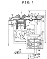
- Fig. 1 schematically shows a multi-cylinder internal combustion engine of electronically controlled fuel injection type in which an intake air control system of the present invention is installed.
- a throttle valve 3 is provided downstream of an air cleaner (not shown).
- a throttle motor 4, which is an actuator for driving the throttle valve 3, is provided at one end of a shaft of the throttle valve 3.
- a throttle opening degree sensor 5 for detecting an opening degree of the throttle valve 3 is provided at the other end of the shaft of the throttle valve 3. That is, the throttle valve 3 is an electronic control throttle (hereinafter referred to simply as an electronic throttle) that is driven to be opened and closed by the throttle motor 4. If a command value for the opening degree of the throttle valve 3 is inputted to the throttle motor 4, the throttle motor 4 causes the opening degree of the throttle valve 3 to approach the opening degree corresponding to the command value.
- An atmospheric pressure sensor 18 is disposed upstream of the throttle valve 3 in the intake passage 2, and a surge tank 6 is disposed downstream of the throttle valve 3 in the intake passage 2.
- a pressure sensor 7 for detecting a pressure of intake air is provided in the surge tank 6.
- a fuel injection valve 8 for feeding pressurized fuel to an intake port from a fuel feed system is provided downstream of the surge tank 6.
- Outputs from the throttle opening degree sensor 5 and the pressure sensor 7 are inputted to an ECU (engine control unit) 10 in which a microcomputer is installed.
- a coolant temperature sensor 11 for detecting a coolant temperature is provided in a coolant passage of a cylinder block of the internal combustion engine 1.
- the coolant temperature sensor 11 generates an electric signal of an analog voltage corresponding to the coolant temperature.
- a three-way catalytic converter (not shown), which simultaneously purifies noxious substances contained in exhaust gas such as hydrocarbon HC, carbon monoxide CO and nitrogen oxide NOx, is provided in an exhaust passage 12.
- an accelerator pedal depression amount signal (an accelerator opening degree signal) from an accelerator opening degree sensor 15 that is attached to an accelerator pedal 14 to detect a depression amount thereof
- a key-position signal (an accessory position, an ON-position and a starter position) from an ignition switch 17 connected to a battery 16
- an engine rotational speed Ne from a rotational speed sensor 21 for detecting a rotational speed of a ring gear 23
- a temperature of lubricating oil from an oil temperature sensor 22
- the starter 19 which is generally composed of a direct-current series-wound motor, is connected to the battery 16 through a starter switch that is turned on when the ignition switch 17 is switched to the starter position. Accordingly, if the ignition switch 17 has been turned on and thereafter switched to the starter position, the starter 19 is activated and the engine 1 is activated. Then, if the engine 1 has started operating, the ECU 10 is supplied with electric power, starts executing its program and receives outputs from the respective sensors. The ECU 10 then controls the throttle motor 4 for opening and closing the throttle valve 3, the fuel injection valve 8 or other actuators.
- the ECU 10 includes an A/D converter for converting analog signals from the respective sensors to digital signals.
- the ECU 10 is provided with an I/O interface 101 to which input digital signals from the respective sensors are inputted and from which signals for driving the respective actuators are outputted, a CPU 102 for performing arithmetic processings, memories such as a ROM 103 and a RAM 104, a clock 105 and the like. These components are interconnected to one another by a bus 106.
- the starter 19 is connected to a B+ terminal of the battery 16 through a starter driving circuit 20. Unless a starter signal ST from the ECU 10 is inputted to the starter driving circuit 20, the starter driving circuit 20 prohibits the starter 19 from being connected to the battery 16.
- the intake passage 2 is closed by temporarily closing the throttle valve 3 when starting the engine 1, so as to generate a negative pressure downstream of the throttle valve 3 and to thereby improve startability of the engine.
- the full-closure position of the throttle valve 3 does not represent a state where the throttle valve 3 is completely in contact with the intake passage 2 but a position where a narrow gap (through which a minimum ISO [idle speed control] flow rate ISC min of air can flow) is formed between the throttle valve 3 and the intake passage 2.
- the key-position signal from the ignition switch 17 and the throttle opening degree signal from the throttle opening degree sensor 5 are inputted to the ECU 10.
- the starter signal ST from the ECU 10 is inputted to the starter driving circuit 20 only if both the starter position signal from the ignition switch 17 and a throttle full-closure signal from the throttle opening degree sensor 5 have been inputted to the ECU 10.
- a control procedure for opening the throttle valve 3 that has been completely closed since the starting of the engine 1 will be described with reference to flowcharts of some embodiments.
- the starter signal ST is outputted to the starter driving circuit 20 only after attainment of the full-closure position by the throttle valve 3.
- the starter 19 then starts its operation.
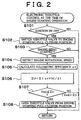
- Fig. 2 is a flowchart showing a first embodiment of a control procedure for opening the throttle valve 3 that has been completely closed since the starting of the engine 1.
- the routine shown in this flowchart is carried out at intervals of a predetermined length of time, for example, several milliseconds.
- step S101 it is determined whether or not the ignition switch 17 has been turned on, namely, whether or not an ON-signal has been inputted to the ECU 10 from the ignition switch 17. If the ignition switch 17 has not been turned on, the routine is terminated without performing any other processings. On the other hand, if it is determined that the ignition switch 17 has been turned on, the operation proceeds to step S102.
- step S102 the throttle motor 4 controls the throttle valve 3 such that the throttle valve 3 assumes its full-closure position at the time of engine starting operation.
- step S103 it is detected whether or not the engine 1 is about to be started, namely, whether or not the starter 19 is in operation. If the starter 19 is not in operation, the routine is terminated. If the starter 19 is in operation, the engine 1 is also in operation. Therefore, the operation proceeds to step S104.
- step S104 a rotational speed of the engine 1 is detected.
- step S105 a volumetric efficiency ⁇ v used for calculation of an amount of consumed air is calculated from an engine rotational speed map preliminarily stored in the ROM 103 of the ECU 10, based on the detected rotational speed of the engine 1.
- the volumetric efficiency ⁇ v represents the ratio of an amount of air sucked to a volume of a combustion chamber. The higher the engine rotational speed becomes, the smaller the volumetric efficiency ⁇ v becomes.
- an amount U of consumed air is calculated in step S106 every time the engine 1 rotates by one revolution.
- ⁇ U ⁇ ( ⁇ v ⁇ Vd ⁇ 1/2)
- the aforementioned cumulative consumed air amount ⁇ U may be corrected based on an intake air temperature.
- step S107 it is determined whether or not the cumulative consumed air amount ⁇ U has become equal to or greater than a volume Vvol of the intake passage 2 downstream of the throttle valve 3. If Vvol > ⁇ U, it is determined that the amount of air corresponding to the volume Vvol of the intake passage 2 downstream of the throttle valve 3 has not been consumed yet, and the routine is terminated without performing any other processings. On the other hand, if Vvol ⁇ ⁇ U, it is determined that the amount of air corresponding to the volume of the intake passage 2 downstream of the throttle valve 3 has all been consumed, and the operation proceeds to step S108. In step S108, the throttle valve 3 is opened from its engine-starting full-closure position to a predetermined opening degree, and the routine is terminated.
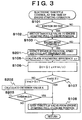
- Fig. 3 is a flowchart showing a second embodiment of a control procedure for opening the throttle valve 3 that has been completely closed since the starting of the engine 1.
- the routine shown in this flowchart is also carried out at intervals of a predetermined length of time, for example, several milliseconds.
- control performed in case of a sudden drop in rotational speed of the engine 1 at the time of engine starting operation is added to the control procedure for opening the throttle valve 3 according to the first embodiment described with reference to Fig. 2. Accordingly, in the following description of the control procedure of the second embodiment, only what is different from the first embodiment will be described.
- step S104 a coolant temperature of the engine, which is regarded as a temperature of the engine, is detected together with an engine rotational speed in step S201.
- step S107 if Vvol > ⁇ U (NO) in step S107, the routine is terminated without performing any other processings. However, in the second embodiment, if Vvol > ⁇ U, the operation proceeds to step S202. In step 302, a criterion value K for a drop rate ⁇ NEdown of the engine rotational speed is calculated from a coolant temperature map stored in the ROM 103 of the ECU 10.
- the drop rate ⁇ NEdown of the engine rotational speed represents a degree of drop in engine rotational speed NE within a predetermined length of time.
- the criterion value K needs to be increased in accordance with a decrease in coolant temperature of the engine.
- Fig. 4 shows an example of a coolant temperature map stored in the ROM 103 of the ECU 10. As can be seen from this map, the higher the engine coolant temperature is, the smaller the criterion value K for the drop rate ⁇ NEdown of the engine rotational speed is made.
- step S203 it is determined in step S203 whether or not the actual drop rate ⁇ NEdown of the engine rotational speed is equal to or higher than the criterion value K calculated in step S202. If ⁇ NEdown ⁇ K in step S203, the routine is terminated without performing any other processings. If ⁇ NEdown ⁇ K in step S203, the operation proceeds to step S108. Further, if Vvol ⁇ ⁇ U in step S107, the same as in the first embodiment holds true. That is, it is determined that the amount of air corresponding to the volume of the intake passage 2 downstream of the throttle valve 3 has all been consumed, and the operation proceeds to step S108. The throttle valve 3 is then opened from its engine-starting full-closure position to a predetermined opening degree, and the routine is terminated.
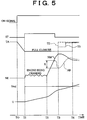
- Fig. 5 is a time chart showing how the ON-position signal of the ignition switch, the starter signal ST from the ECU 10, a throttle opening degree TA as an opening degree of the throttle valve 3, the engine rotational speed NE and an amount U of air consumed by the engine 1 change with the lapse of time, in the control procedure of the first and second embodiments described with reference to Figs. 2 and 3.
- step S101 If it is determined in step S101 that the ignition switch 17 has been turned on, the ON-signal at a time T0 attains a high level. If the ignition switch 17 is turned on, the control in step S102 causes the throttle motor 4 to close the throttle valve 3, so that the throttle opening degree TA decreases. If the throttle valve 3 is completely closed at a time T1, the starter signal ST is outputted from the ECU 10 to the starter driving circuit 20. The starter 19 then rotates and the engine 1 enters its cranking state. At this moment, the operation proceeds from step S103 to step S104, where a cumulative rotational speed ⁇ NE after the engine starting operation is calculated according to the procedure in steps S104 through S106.
- step S108 After the engine 1 is started at a time T2, the rotational speed of the engine 1 rises as indicated by a solid line NM, reaches a predetermined rotational speed, slightly drops and then settles down. After the time T2, an amount U of air consumed by the engine 1 continues to be calculated constantly.
- Vvol becomes equal to ⁇ U at a time T4 which is later than the time T2.
- the throttle valve 3 is opened from its engine-starting full-admission position, and the throttle opening degree TA increases to a predetermined opening degree, for example, an idle opening degree.
- the throttle valve 3 is opened, and the throttle opening degree TA increases to a predetermined opening degree as indicated by a broken line TD.
- the throttle valve 3 may be opened to the predetermined opening degree at a breath at the time T3 or may be opened gradually as indicated by an alternate long and short dash line TS.
- the amount of air sucked into the combustion chamber is calculated using the cumulative rotational speed ⁇ NE, the volumetric efficiency ⁇ v and the cylinder volume of the engine 1. If the amount of air corresponding to the volume of the intake passage 2 downstream of the throttle valve 3 has all been consumed, the throttle valve 3 that has been completely closed since the engine starting operation is opened. Accordingly, the throttle valve 3 can be held completely closed within such a range that the engine does not fail to be started due to a deficiency in amount of intake air in the engine. Consequently, both reduction of concentration of emission substances and enhancement of startability can be achieved.
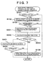
- Fig. 6 is a flowchart showing a third embodiment of a control procedure for opening the throttle valve 3 that has been completely closed since the starting of the engine 1.
- the routine shown in this flowchart is also carried out at intervals of a predetermined length of time, for example, several milliseconds.
- the throttle valve 3 is opened if a predetermined length of time has elapsed after the starting of the engine 1.
- step S103 if the result is YES in step S103 (if the starter 19 is in operation), the operation proceeds to step S301.
- step S301 conditions concerning a volume of the engine 1 downstream of the throttle valve 3, a coolant temperature of the engine, a temperature of lubricating oil and an atmospheric pressure are read, and a holding time Tclose for holding the throttle valve completely closed is calculated according to those conditions.
- a holding time Tclose for holding the throttle valve completely closed is calculated according to those conditions.
- Fig. 8A the higher the atmospheric pressure becomes, the longer the holding time Tclose is made.
- Fig. 8B the higher the coolant temperature or the oil temperature becomes, the shorter the holding time Tclose is made.
- an elapsed time ⁇ TM after the starting of the engine 1 is calculated.
- step S303 the elapsed time ⁇ TM after the starting of the engine 1 is compared with the holding time Tclose for holding the throttle valve 3 completely closed. If ⁇ TM ⁇ Tclose, the routine is terminated without performing any other processings. If ⁇ TM ⁇ Tclose, the operation proceeds to step S108.
- step S401 a criterion value K for the drop rate ⁇ NEdown of the engine rotational speed is calculated from a coolant temperature map (the same map as in Fig. 4).
- step S402 it is determined whether or not the actual drop rate ⁇ NEdown of the engine rotational speed is equal to or higher than the criterion value K calculated in step S401. If ⁇ NEdown ⁇ K, the routine is terminated without performing any other processings. If ⁇ NEdown ⁇ K, the operation proceeds to step S108 where the throttle valve 3 is opened from its engine-starting full-admission position to a predetermined opening degree. The routine is then terminated. If the result in step S303 is YES ( ⁇ TM ⁇ Tclose), the operation proceeds to step S108 where the throttle valve 3 is opened from its engine-starting full-closure position to a predetermined opening degree. The routine is then terminated.
- Fig. 9 is a time chart showing how the ON-position signal of the ignition switch 17, the starter signal STR from the ECU 10, the throttle opening degree TA as an opening degree of the throttle valve 3, the engine rotational speed NE and the elapsed time after the engine starting operation change with the lapse of time, in the control procedure in the third and fourth embodiments described with reference to Figs. 6 and 7.
- step S103 a holding time Tclose for holding the throttle valve 3 completely closed is calculated.
- step S108 the throttle valve 3 is opened from its engine-starting full-closure position, and the throttle opening degree TA increases to a predetermined opening degree, for example, an idle opening degree.
- the throttle valve 3 is opened through the control in step S402, and the throttle opening degree TA increases to a predetermined opening degree as indicated by the broken line TD.
- the throttle valve 3 may be opened to the predetermined opening degree at a breath at the time T3 or may be opened gradually as indicated by the alternate long and short dash line TS.
- the holding time Tclose for holding the throttle valve 3 completely closed is calculated according to the type of the engine 1 and environmental conditions. If the elapsed time ⁇ TM after the starting of the engine 1 becomes equal to or longer than the holding time Tclose, the throttle valve 3 is opened. Therefore, the throttle valve 3 can be held completely closed within such a range that the engine does not fail to be started due to a deficiency in amount of intake air in the engine. Consequently, both reduction of concentrations of emission substances and improvement in startability can be achieved.
- Fig. 10 is a flowchart showing a fifth embodiment of a control procedure for opening the throttle valve 3 that has been completely closed since the starting of the engine 1.
- the routine shown in this flowchart is also carried out at intervals of a predetermined length of time, for example, several milliseconds.
- the throttle valve 3 is opened.
- step S103 if the result in step S103 is YES (if the starter 19 is in operation), the operation proceeds to step S501.
- step S501 the pressure sensor 7 detects an intake air pressure P in the surge tank 6 of the engine 1.
- step S502 the intake air pressure P in the surge tank is compared with a reference pressure Pref. If P ⁇ Pref, the routine is terminated without performing any other processings. If P ⁇ Pref, the operation proceeds to step S108, where the throttle valve 3 is opened from its engine-starting full-closure position to a predetermined opening degree. The routine is then terminated.
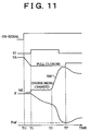
- Fig. 11 is a time chart showing how the ON-position signal of the ignition switch 17, the starter signal ST from the ECU 10, the throttle opening degree TA as an opening degree of the throttle valve 3, the engine rotational speed NE and the intake pipe pressure P change with the lapse of time, in the control procedure in the fifth embodiment.
- step S501 an intake pipe pressure P in the surge tank 6 is detected.
- the intake pipe pressure P continues to be detected constantly.
- P becomes equal to Pref at a time TP which is later than the time T2.
- the throttle valve 3 is opened through the control in step S108, and the throttle opening degree TA slightly increases.
- the intake air pressure P in the surge tank 6 after the starting of the engine 1 is detected. If the intake air pressure P has decreased to the reference value Pref, the throttle valve 3 that has been completely closed since the engine starting operation is opened.
- the throttle valve 3 can be held completely closed within such a range that the engine does not fail to be started due to a deficiency in amount of intake air in the engine. Consequently, both reduction of concentrations of emission substances and improvement in startability can be achieved.
- the control according to the aforementioned embodiment makes it possible to open the throttle valve at an appropriate timing when starting the engine. Therefore, it is possible to increase an amount of intake air in the engine while maintaining stabilized combustion.
- Fig. 12 shows how the engine rotational speed and the opening degree of the throttle valve change when starting the engine.
- the axis of ordinate represents time
- the upper part of the axis of abscissa represents throttle opening degree
- the lower part of the axis of abscissa represents rotational speed of the engine.
- the fuel injection amount is proportional to an open period of the fuel injection valve 8, namely, to a fuel injection time. Therefore, the fuel injection amount is calculated through calculation of a fuel injection time.
- the fuel injection time is calculated according to a first engine-starting fuel injection time calculating routine from the time t2 to the time t3. From the time t3 to the time t5 indicated by a broken line, the fuel injection time is calculated according to a second engine-starting fuel injection time calculating routine, based on a load factor of the engine 1 that has been calculated in accordance with a rotational speed of the engine 1 and an opening degree of the throttle valve 3. After the time t5, the fuel injection time is calculated according to a post-engine-starting fuel injection time calculating routine, based on a load factor of the engine 1 that has been calculated in accordance with a rotational speed of the engine 1 and an intake pressure.
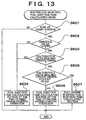
- Fig. 13 is a flowchart of a routine for selecting modes for calculating fuel injection amount and time.
- This routine which belongs to a main routine, is carried out at intervals of a predetermined length of time, for example, 1 milliseconds.
- step S601 it is determined in step S601 whether or not the ignition switch (IGSW) 17 is at the starter position. If the IGSW 17 is at the starter position, the operation proceeds to step S601. If the IGSW 17 is not at the starter position, the routine is terminated. It is determined in step S602 whether or not the throttle valve 3 has reached its full-closure position, namely, whether or not the intake passage 2 has been closed. If the result is YES in step S602, the operation proceeds to step S603. If the result is NO in step S602, the operation proceeds to step S604.
- IGSW ignition switch
- step S603 It is determined in step S603 whether or not a timing for starting to open the throttle valve 3 has been reached. If the result in step S603 is YES, the operation proceeds to step S605. If the result in step S603 is NO, the operation proceeds to step S604.
- the timing for starting to open the throttle valve 3 corresponds to the time t3 when all the air (hereinafter referred to as residual air) that exists in the intake passage 2 downstream of the throttle valve 3 at the time t2 shown in Fig. 12 is sucked into the cylinders of the engine 1.
- the amount of residual air can be calculated from a design drawing of the intake passage 2. Alternatively, the amount of residual air can be calculated by measuring a volume of water poured into the intake passage 2 downstream of the throttle valve 3 with all the intake valves of the engine 1 being closed.
- the number of revolutions of the engine 1 required to suck all the amount of residual air thus calculated can be calculated from a cylinder volume per revolution of the engine 1 and a volumetric efficiency of the intake system. For example, when the cylinder volume of the engine 1 is 1600cc, exhaust gas of 800cc is discharged per revolution of the engine 1.
- a map for calculating an amount of intake air per unit time from a rotational speed of the engine 1 may be prepared in advance. In this case, it is possible to calculate a timing when the amount of intake air reaches the amount of residual air, from a change in rotational speed after the starting of the engine.
- a routine for calculating a first engine-starting fuel injection time TAUSTa is carried out in step S604. It is determined in step S605 whether or not the opening degree of the throttle valve 3 has reached an opening degree TAFI for supplying an amount of air corresponding to a first idle rotational speed. If TA ⁇ TAFI, the operation proceeds to step S606. If TA ⁇ TAFI, the operation proceeds to step S607. In step S606, a routine for calculating a second engine-starting fuel injection time TAUSTb is carried out. In step S607, a routine for calculating a post-engine-starting fuel injection time TAU is carried out.
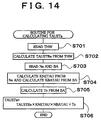
- Fig. 14 is a flowchart of the routine for calculating the first engine-starting fuel injection time TAUSTa.
- This processing routine is carried out in the main routine.
- a coolant temperature THW of the engine 1 is read from the coolant temperature sensor 11 disposed in a water jacket of an engine block.
- a first base fuel injection time TAUSTBa is calculated from a map stored in the ROM based on the read coolant temperature THW.
- an engine rotational speed Ne is read from the rotational speed sensor 21, and a battery voltage BA is read through an A/D converter (not shown).
- step S704 correction factors KNETAU and NBATAU are calculated from the maps stored in the ROM, based on the rotational speed Ne and the battery voltage BA that have been read.
- step S705 an invalid injection time Ts is calculated from the map stored in the ROM, based on the read battery voltage BA.
- the invalid injection time represents an operational delay time from the driving of the fuel injection valve 8 to the actual opening thereof, namely, a time when no fuel is injected despite issuance of a command to open the fuel injection valve 8.
- step S706 a first engine-starting fuel injection time TAUSTa (milliseconds) is calculated according to a formula (2) shown below, using the base fuel injection time TAUSTBa, the correction factors KNETAU and NBATAU, and the invalid injection time Ts.
- TAUSTa TAUSTBa ⁇ KNETAU ⁇ NBATAU + Ts
- Fig. 15 is a flowchart of a routine for calculating the second engine-starting fuel injection time TAUSTb. This processing routine is carried out in the main routine.
- step S801 various signal input data are read.
- step S802 a base fuel injection time TAUSTBb at the time of the second engine starting operation corresponding to an operational state of the engine 1 is calculated from a two-dimensional map (not shown) stored in the ROM, based on data concerning the rotational speed of the engine 1 and the throttle opening degree TA that have been read.
- the throttle opening degree TA is used as a parameter indicative of a loaded condition of the engine 1.
- step S803 a correction factor Kk determined by the coolant temperature THW, the intake air temperature THA and the like is calculated. Then in step S804, an invalid injection time Ts is calculated from the map stored in the ROM, based on the battery voltage BA.
- step S805 a post-engine-starting fuel injection time TAUSTb (milliseconds) is calculated from a following formula (3) shown below, using the second base fuel injection time TAUSTb, the correction factor Kk and the invalid injection time Ts calculated in steps S802, S803 and S804.
- TAUSTb Kk ⁇ TAUSTBb + Ts
- Fig. 16 is a flowchart of a routine for calculating a post-engine-starting fuel injection time TAU. This processing routine is carried out in the main routine.
- step S901 various signal input data are read.
- step S902 a base fuel injection time TP corresponding to an operational state of the engine 1 is calculated from a two-dimensional map stored in the ROM, based on data concerning the rotational speed Ne of the engine 1 and the intake air pressure P that have been read.
- a correction factor a which is determined by the coolant temperature THW, the throttle opening degree TA, the intake air temperature THA and the like, is calculated.
- step S904 an invalid injection time Ts is calculated from a map stored in the ROM based on the battery voltage BA.
- an air-fuel ratio correction factor FAF is calculated based on a difference between the air-fuel ratio of the engine 1 determined from an output of the O 2 sensor 13 and a map (not shown), and a target air-fuel ratio (e.g. a stoichiometric air-fuel ratio)
- the air-fuel ratio correction factor FAF is a feedback correction factor for performing control such that the air-fuel ratio of the engine 1 becomes equal to a stoichiometric air-fuel ratio, in accordance with an output value of an air-fuel ratio sensor circuit (not shown) of the O 2 sensor 13.
- the air-fuel ratio correction factor FAF is equal to 1.0 when neither reducing correction nor increasing correction is made.
- the air-fuel ratio correction factor FAF is greater than 0.8 and smaller than 1.0 when reducing correction is made.
- the air-fuel ratio correction factor FAF is greater than 1.0 and smaller than 1.2 when increasing correction is made.
- a post-engine-starting fuel injection time TAU is calculated from a formula (4) shown below, using the base fuel injection time TP, the correction factor ⁇ , the invalid injection time Ts and the air-fuel ratio correction factor FAF.
- TAU TP ⁇ ⁇ (FAF + ⁇ ) + Ts
- ⁇ represents a correction factor that is different from FAF.
- the fuel injection valve 8 corresponding to each cylinder of the engine 1 is opened for a fuel injection time that has been calculated in the aforementioned respective routines for calculating fuel injection amount and time. As a result, a suitable amount of fuel and a suitable amount of air are supplied to each of the cylinders.
- the opening degree of the throttle valve is adjusted according to a depression amount of the accelerator pedal when starting the engine, and an amount of air required to prevent the plug from smoldering or to eliminate other inconveniences is supplied to the engine.
- the startability of the engine can thereby be improved.
- Fig. 17 is a flowchart of a routine for selecting a switching control mode of the opening degree of the throttle valve.
- the routine shown in this flowchart is carried out at intervals of a predetermined length of time, for example, 100 milliseconds.
- step S1001 it is determined in step S1001 whether or not the ignition switch (IGSW) 17 is at the starter position. If the IGSW 17 is at the starter position, the operation proceeds to step S1002. If the IGSW 17 is not at the starter position, the routine is terminated.
- step S1002 a depression amount PA of the accelerator pedal 14 depressed by the driver is read.
- step S1003 It is determined in step S1003 whether or not the depression amount PA is smaller than a first depression amount PA1. If PA ⁇ PA1, the operation proceeds to step S1004 where later-described first switching control of the throttle valve 3 is performed. If PA ⁇ PA1, the operation proceeds to step S1005.
- step S1005 It is determined in step S1005 whether or not the depression amount PA read in step S1002 is equal to or greater than the first depression amount PA1 and smaller than a second depression amount PA2. If PA1 ⁇ PA ⁇ PA2, the operation proceeds to step S1006. If PA ⁇ PA2, the operation proceeds to step S1007. In step S1006, later-described second switching control of the throttle valve 3 is performed. In step S1007, later-described third switching control of the throttle valve 3 is performed.
- the first switching control of the opening degree of the throttle valve is performed based on Fig. 12 as described above.
- the throttle valve 3 is closed to its full-closure position after the engine starting operation, and control is performed such that the throttle valve 3 is gradually opened from a time when air in the intake passage 2 downstream of the throttle valve 3 is admitted into the cylinders to a time when the engine 1 reaches a predetermined rotational speed, namely, a first idle rotational speed.
- the first switching control is designed to prevent a great amount of intake air from flowing into the engine 1 by closing the intake passage 2 when starting the engine 1 and to promote gasification of fuel by increasing a negative pressure in the intake pipe. Accordingly, fuel injected from the fuel injection valve 8 is sufficiently atomized and the startability of the engine is improved.
- the second switching control of the opening degree of the throttle valve will be described with reference to Fig. 18.
- the opening degree of the throttle valve 3 set by the first switching control is indicated by a broken line.
- the second switching control of the opening degree of the throttle valve 3 is designed to open the throttle valve 3 to an opening degree TAFI corresponding to an amount of air required for fast idling when the depression amount PA of the accelerator pedal 14 is equal to or greater than the first depression amount PA1 and smaller than the second depression amount PA2.
- the throttle valve 3 is opened to an opening degree corresponding to an amount of air required for fast idling by depressing the accelerator pedal 14 to a certain extent. Thereby the driver's intention can be reflected, so that the startability of the engine 1 is improved.
- the third switching control of the opening degree of the throttle valve will be described with reference to Fig. 19.
- the opening degree of the throttle valve 3 set by the first switching control and the rotational speed of the engine 1 are indicated by broken lines.
- the third switching control of the opening degree of the throttle valve 3 is designed to open the throttle valve 3 according to the depression amount PA of the accelerator pedal when the depression amount PA of the accelerator pedal 14 is equal to or greater than the second depression amount PA2.
- the throttle valve 3 is opened to an opening degree corresponding to the depression amount PA of the accelerator pedal by greatly depressing the accelerator pedal 14. Thereby the driver's intention can be reflected, so that the startability of the engine 1 is improved.
- driving control of the throttle valve 3 and the fuel injection control may be performed.
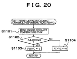
- the driving control of the throttle valve 3 and the fuel injection control will be described hereinafter.
- step S1101 shown in Fig. 20 an engine coolant temperature THW detected by the coolant temperature sensor 11 is read. It is determined in step S1102 whether or not the coolant temperature is within a predetermined temperature range A to B °C. If the coolant temperature THW is outside the range, the operation proceeds to step S1104 where a throttle valve closing control performing flag FTHVC is set to "0". The routine is then terminated. On the other hand, if the coolant temperature THW is within the range, the operation proceeds to step S1103 where the throttle valve closing control performing flag FTHVC is set to "1". The routine is then terminated. When the throttle valve closing control performing flag FTHVC is set to "1", the throttle valve closing control is performed.
- the throttle valve closing control performing flag FTHVC which is set to "1" when the coolant temperature THW is within the range of A ⁇ THW ⁇ B in starting the engine 1, is reset after the lapse of a predetermined length of time from the starting of the engine 1.
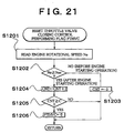
- the time for resetting the throttle valve closing control performing flag FTHVC can be set, for example, by taking into account a time required for an amount of air downstream of the throttle valve upon opening of the throttle valve to reach null after the engine starting operation. This control will be described with reference to the flowchart shown in Fig. 21.
- the routine shown in Fig. 21 is also carried out at intervals of a predetermined length of time, for example, several milliseconds, in the initial routine only when the engine 1 is started.
- an engine rotational speed Ne is read in step S1201. It is determined in the following step S1202 whether or not the engine rotational speed Ne is equal to or higher than a set rotational speed Nes (e.g. 400 rpm). If the engine rotational speed Ne is lower than the set rotational speed Nes, it is determined that the engine has not been started yet, and the operation proceeds to step S1203 where a post-engine-starting elapsed time counter CNT is cleared. The routine is then terminated.
- a set rotational speed Nes e.g. 400 rpm
- step S1204 the value of the post-engine-starting elapsed time counter CNT is incremented by 1.
- step S1205 it is determined whether or not the value of the post-engine-starting elapsed time counter CNT has reached a reference counting value C indicative of a predetermined length of time. If the value of the post-engine-starting elapsed time counter CNT has not reached the reference counting value C, the operation proceeds to step S1206 where the throttle valve closing control performing flag FTHVC is set to "0". The routine is then terminated. In this manner, the throttle valve closing control performing flag FTHVC, which has been set to "1" at the time of engine starting operation, is set to "0" after the lapse of a predetermined length of time from the starting of the engine.
- Fig. 22 is a characteristic diagram showing an air consumption ratio R in the intake system in the case where the air existing in the volume Vvol in the intake passage 2 downstream of the throttle valve 3 decreases with the lapse of time when the engine 1 is cranked and started after the throttle valve 3 has been completely opened.
- the air consumption ratio R is a value obtained by dividing a cumulative amount ⁇ U of air consumed by the internal combustion engine 1 by an amount Vvol of air in the intake system. When the cumulative air consumption amount ⁇ U is small, the air consumption ratio R is close to zero. As the cumulative air consumption amount ⁇ U increases, the air consumption ratio R increases and approaches 1. That is, the air consumption ratio R is in the range of 0 ⁇ R ⁇ 1. Because the air consumption ratio R in the intake system is hereinafter used as a coefficient, it will be referred to as a transitional coefficient.
- the engine rotational speed is controlled so as to calculate a transitional coefficient R in advance.
- the transitional coefficient R thus calculated can be stored in the ROM 103 of the ECU 10.
- the characteristic wherein the air existing in the volume Vvol downstream of the throttle valve 3 that has been opened since the starting of the engine decreases with the lapse of time can be calculated based on a rotational speed of the engine 1 (the rotational speed of the engine 1 is a known value because it is controlled on the side of the ECU 10) and a volumetric efficiency ⁇ v used for calculation of an air consumption amount obtained from the map of the rotational speed of the engine 1. That is, the transitional coefficient R can be calculated from the cumulative air consumption amount ⁇ U.
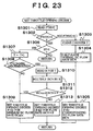
- Fig. 23 is a flowchart showing a procedure of setting an opening degree of the electronically controlled throttle valve 3 when starting the engine 1.
- the routine shown in this flowchart is carried out at intervals of a predetermined length of time, for example, several milliseconds.
- step S1301 the value of the throttle valve closing control performing flag FTHVC is read.
- step S1302 it is determined whether or not the throttle valve closing control performing flag FTHVC is set to "1". If the throttle valve closing control performing flag FTHVC is set to "0", it is determined that the engine 1 has already been started. The operation then proceeds to step S1303 where a time counter T is cleared. The operation then proceeds to step S1304.
- step S1304 a normal ISC flow rate ISCN is calculated.
- step S1305 a throttle valve opening degree ⁇ thv corresponding to the normal ISC flow rate ISCN is set as an opening degree of the throttle valve. The routine is then terminated.
- step S1306 It is determined in step S1306 whether or not the starter signal ST assumes a value of 1, namely, whether or not intake air is being sucked into the combustion chamber of the engine 1. If intake air is not being sucked into the combustion chamber, the routine is terminated. If intake air is being sucked into the combustion chamber, the operation proceeds to step S1307.
- step S1307 the value of the time counter T is incremented so as to calculate a cumulative time when the engine sucks intake air.
- step S1308 it is determined whether or not discrimination of the cylinders has been finished after the cranking of the engine 1. If it is determined in step S1308 that discrimination of the cylinders has not been finished yet, the operation proceeds to step S1309. A throttle opening degree ⁇ th1 corresponding to a minimum ISC flow rate ISCmin is set as the opening degree of the throttle valve. The routine is then terminated.
- step S1310 a transitional coefficient (an air consumption ratio in the intake system) R corresponding to the value of the time counter T calculated in step S1307 is read from the ROM 103.
- step S1311 a normal ISC flow rate ISCN is calculated as in step S1304. The normal flow rate ISCN is multiplied by the transitional coefficient R calculated in step S1310 so as to obtain a transitional air amount ISCN ⁇ R.
- step S1312 the minimum ISC flow rate ISCmin is compared with the transitional air amount ISCN ⁇ R calculated in step S1311. If ISCmin ⁇ ISCN ⁇ R, the operation proceeds to step S1309 where an opening degree ⁇ th1 for a minimum ISC flow rate ISCmin is set as the opening degree of the throttle valve. If ISCmin ⁇ ISCN ⁇ R, the operation proceeds to step S1313 where a throttle opening degree ⁇ th2 for the transitional air amount R is set. The routine is then terminated.
- step S1312 may be performed after the engine has rotated by predetermined revolutions following the cranking thereof, or after a predetermined length of time has elapsed following the cranking of the engine.
- the transitional coefficient R gradually increases in accordance with an increase in the counting value of the time counter T and approaches 1. Accordingly, the value of the throttle opening degree ⁇ th2 set in step S1313 gradually increases and finally reaches the normal ISC flow rate ISCN calculated in step S1305.
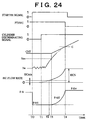
- Fig. 24 is a time chart showing how the starter signal, the throttle valve closing control performing flag FTHVC, the cylinder discrimination signal, the post-engine-starting counter CNT, the engine Ne, the ISC flow rate and the throttle opening degree ⁇ th change.
- the throttle opening degree 0th is set to a first opening degree ⁇ th1. This is because the cylinder discrimination signal assumes a value of 0 at this moment. After that, while the engine is being cranked until a time T1, air flows at the minimum required ISC flow rate ISCmin with the throttle valve 3 being at the opening degree ⁇ th1, that is, being almost completely closed.
- the minimum required ISC flow rate ISCmin is compared with the transitional air amount ISCN ⁇ R. Because ISCmin ⁇ ISCN ⁇ R until the time T2, the throttle opening degree is set to an opening degree ⁇ th1 for the minimum ISC flow rate ISCmin. On the other hand, if ISCmin ⁇ ISCN ⁇ R at the time T2, the throttle opening degree is set to an opening degree ⁇ th2 for the transitional air amount ISCN ⁇ R.
- the cranking is continued for a predetermined length of time from the time T0, and the engine is started at a time that is later than the time T1 and earlier than the time T2.
- the engine rotational speed Ne rises. If the engine rotational speed Ne reaches a predetermined rotational speed Nes at a time T3 that is later than the time T2, the post-engine-starting counter CNT starts its counting operation.
- the throttle opening degree ⁇ th2 gradually increases in accordance with an increase in transitional coefficient R.
- the ISC flow rate also increases correspondingly and gradually approaches the normal ISC flow rate ISCN.
- the value of the post-engine-starting counter CNT is thus set to the predetermined value C at a time close to the time when the ISC flow rate becomes close to the normal ISC flow rate ISCN due to an increase in throttle opening degree ⁇ th2, since the throttle opening degree ⁇ th2 upon termination of the opening control of the throttle valve is close to a throttle opening degree ⁇ thv obtained through a normal calculation formula, it is possible to prevent an amount of intake air from changing greatly at the time of transition from the opening control to the closing control of the throttle valve.
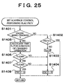
- Fig. 25 is a flowchart showing a procedure of setting a scavenge control performing flag FSCV in the internal combustion engine 1.
- the routine shown in this flowchart is also carried out at intervals of a predetermined length of time, for example, several milliseconds, in the initial routine only when the engine 1 is started.
- the scavenge control is performed when the engine does not start operating even if it is cranked by the starter 19 after the throttle valve 3 has been completely closed because of the turning-on of the ignition switch 17.
- the scavenge control is designed to scavenge unburnt fuel in the combustion chamber by stopping fuel injection from the fuel injection valve 8 and to thereby improve the startability of the engine.
- the scavenge control performing flag FSCV is set to "1"
- step S1403 the value of a cranking time counter is cleared and the cranking duration time Tc is set to zero.
- step S1404 the scavenge control performing flag FSCV is set to "0". The routine is then terminated.
- step S1405 the cranking duration time Tc is calculated using the cranking time counter.
- step S1406 it is determined whether or not the value of the cranking duration time Tc has become equal to or longer than a reference time MN.
- the reference time MN is set to be longer than the latest time that is generally required for the engine to be started since the starting of the cranking operation. If Tc ⁇ MN in step S1406, the operation proceeds to step S1404 where the scavenge control performing flag FSCV is set to "0". The routine is then terminated. If Tc ⁇ MN in step S1406, the operation proceeds to step S1407.
- This determination is intended to stop the scavenge control on condition that the scavenge control has lasted for the predetermined length of time L. In other words, the determination is intended to set a timing for resetting the scavenge control performing flag FSCV to "0". Therefore if Tc ⁇ MX in step S1407, the operation proceeds to step S1408 where the scavenge control performing flag FSCV is set to "1". The routine is then terminated. If Tc > MX, the operation proceeds to step S1404 where the scavenge control performing flag FSCV is set to "0". The routine is then terminated.
- the scavenge control is performed only when MN ⁇ the cranking duration time Tc ⁇ MX.
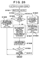
- Fig. 26 is a flowchart showing a procedure of setting an opening degree of the electronically controlled throttle valve 3 when starting the engine 1.
- the routine shown in this flowchart is carried out at intervals of a predetermined length of time, for example, several milliseconds. As described above, it is assumed herein that the gap formed when the throttle valve 3 is at its full-closure position is a gap allowing the ISC flow rate of air to flow.
- step S1501 a value of the throttle valve closing control performing flag FTHVC and a value of the scavenge control performing flag FSCV are read.
- step S1502 it is determined whether or not the throttle valve closing control performing flag FTHVC has been set to "1".
- step S1502 If it is determined in step S1502 that the throttle valve closing control performing flag FTHVC has been set to "0", it is determined that the engine 1 has already been started. The operation then proceeds to step S1503 where a normal ISC flow rate ISCN is calculated. In the following step S1504, a throttle opening degree ⁇ thv corresponding to the normal ISC flow rate ISCN is set as the opening degree ⁇ th of the throttle valve. The routine is then terminated.
- step S1502 If it is determined in step S1502 that the throttle valve closing control performing flag FTHVC has been set to "1", it is determined that the engine 1 is being started. The operation then proceeds to step S1505 where it is determined whether or not fuel injection has been started with intake air being sucked into the combustion chamber of the engine 1.
- step S1506 a throttle opening degree ⁇ th1 for a minimum ISC flow rate ISCmin is set as the opening degree of the throttle valve. The routine is then terminated.
- step S1505 If it is determined in step S1505 that fuel injection has been started, the operation proceeds to step S1507.
- step S1507 a learning value ISCG of the ISC flow rate at the time of idling stored in the RAM 104 of the ECU 10, an atmospheric pressure AP detected by the atmospheric pressure sensor 18, an atmospheric pressure correction factor AH stored in the ROM 103 of the ECU 10, and operational state parameters of auxiliaries such as an air-conditioner and electrical loads installed in the engine 1 are read.
- the learning value ISCG of the ISC flow rate at the time of idling is corrected based on those operational state parameters so as to calculate an ISC flow rate ISCH.
- step S1508 a throttle opening degree ⁇ th2 for the calculated ISC flow rate ISCH is set as the opening degree ⁇ th of the throttle valve. The operation then proceeds to step S1509.
- step S1509 It is determined in step S1509 whether or not the value of the scavenge control performing flag FSCV read in step S1509 is "1". If the scavenge control performing flag FSCV has been set to "0", it is determined that the scavenge control has not been performed. The routine is then terminated.
- step S1510 If the scavenge control performing flag FSCV has been set to "1" in step S1510, it is determined that the scavenge control has been performed. The operation then proceeds to step S1510.
- the throttle valve opening degree ⁇ th is set to a great opening degree ⁇ th0 such that the opening degree of the throttle valve 3 increases during the scavenge control and a large amount of intake air flows toward the combustion chamber.
- the opening degree ⁇ th0 can be set to an opening degree for completely opening the throttle valve 3.
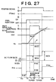
- Fig. 27 is a time chart showing how the starter signal, the throttle valve closing control performing flag FTHVC, the fuel injection, the scavenge control performing flag FSCV, the engine rotational speed Ne, the ISC flow rate and the throttle valve opening degree ⁇ th change.
- the throttle opening degree ⁇ th is set to a first opening degree ⁇ th1. After that, while the engine is being cranked until a time T1, air flows at the minimum required ISC flow rate ISCmin with the throttle valve 3 being at the opening degree ⁇ th1, that is, being almost completely closed.
- the learning value ISCG of the ISC flow rate at the time of idling is read out from the RAM 104 and corrected by means of the operational state parameters of the engine 1 so as to calculate an ISC flow rate ISCH.
- the opening degree ⁇ th of the throttle valve 3 for the ISC flow rate ISCH is then set to an opening degree ⁇ th2.
- the rotational speed Ne of the engine starts increasing as indicated by a solid line after continuation of the cranking operation for a predetermined length of time since the time T1. If the engine rotational speed Ne reaches a predetermined rotational speed Nes at a time T2 which is later than the time T1, the post-engine-starting counter CNT starts its counting operation. In this state, the ISC flow rate ISCH of air flows with the throttle valve 3 being at the opening degree ⁇ th2, that is, being almost completely opened. After that, if the post-engine-starting counter CNT reaches a predetermined value C at a time T3, the throttle valve closing control performing flag FTHVC is set to "0" and the ISC flow rate is calculated through a normal calculation formula. The throttle opening degree ⁇ th is set to a throttle opening degree ⁇ thv corresponding to the normal ISC flow rate that has been calculated, and the ISC flow rate of air flows correspondingly.
- the cranking operation is continued as indicated by a broken line F even after the time T1 and the rotational speed Ne of the engine does not increase.
- the scavenge performing flag FSCV is set to "1" at a time (T0 + MN) when a reference time MN has elapsed since the time T0 corresponding to the starting of the cranking operation. If the scavenge performing flag FSCV is set to "1", fuel injection is stopped as indicated by a broken line, and ignition cut-off operation for the ignition plug in the combustion chamber is performed.
- the throttle opening degree ⁇ th is set to an opening degree ⁇ tho as indicated by a broken line.
- the throttle valve 3 is completely opened or almost completely opened.
- the throttle opening degree ⁇ th is reset to the original opening degree ⁇ th2, and the normal control is performed.
- the scavenge control is performed during the closing control of the throttle valve at the time of engine starting operation, the throttle valve 3 is completely opened temporarily. Therefore, there is no obstacle to the scavenge control.
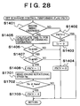
- Fig. 28 shows how to perform control in such a case.
- step S1701 After the scavenge performing flag FSCV has been set to "1" in step S1408, an engine rotational speed Ne is read in step S1701.
- step S1702 it is determined whether or not the engine rotational speed Ne has become equal to or higher than a reference rotational speed Neref. If the engine rotational speed Ne is lower than the reference rotational speed Neref, it is determined that the engine has not been started yet. The routine is then terminated without performing any other processings. If the engine rotational speed Ne has become equal to or higher than the reference rotational speed Neref in step S1702, it is determined that the engine has been started.
- step S1703 the scavenge performing flag FSCV is set to "0" so as to cancel the scavenge mode.
- This control ensures that the engine rotational speed Ne does not rise excessively even if the engine has been started in the scavenge mode.
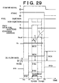
- Fig. 29 is a time chart showing how the starter signal, the throttle valve closing control performing flag FTHVC, the fuel injection, the scavenge performing flag FSCV, the post-engine-starting counter CNT, the engine rotational speed Ne, the ISC flow rate and the throttle opening degree ⁇ th change when performing the control shown in Fig. 28.
- the engine 1 is started in the scavenge mode after a predetermined length of time R has elapsed since the time (T0 + MN), and the engine rotational speed Ne increases as indicated by a broken line S and reaches the reference rotational speed Nref at a time TS. If the scavenge mode is continued in this state, the engine rotational speed Ne may increase excessively as indicated by an alternate long and two short dashes line U. Therefore, the scavenge performing flag FSCV is set to "0" at the time TS.
- the throttle opening degree ⁇ th is reset from the opening degree ⁇ tho to the opening degree ⁇ th2. Therefore, the ISC flow rate is also returned to the original flow rate ISCH, so that the engine rotational speed Ne is prevented from rising as indicated by a broken line V.
- the present invention can effectively be applied not only to a case where the electronically controlled throttle valve 3 closes the intake passage of the internal combustion engine but also to a case where an electronically controlled intake control valve is separately provided in the intake passage of the internal combustion engine.
- the present invention proposes an internal combustion engine(1) having an intake passage that is closed at the time of engine starting operation wherein a holding time for completely closing a throttle valve is made as long as possible within such a range that the engine does not fail to be started.
- the throttle valve is held at its full-closure position when an ignition switch is turned on.
- an amount of air consumed by the engine is calculated based on a cumulative rotational speed of the engine, a cylinder volume of the engine, and a parameter of volumetric efficiency corresponding to an engine rotational speed. It is determined whether or not the amount of air consumed has become equal to an amount of air existing in a volume downstream of the throttle valve.
- the throttle valve is opened to a predetermined opening degree. Consequently, the engine is started smoothly without causing any operational failures, which makes it possible to lower concentrations of emission substances.
Applications Claiming Priority (10)
| Application Number | Priority Date | Filing Date | Title |
|---|---|---|---|
| JP2214099 | 1999-01-29 | ||
| JP2214099A JP3598863B2 (ja) | 1999-01-29 | 1999-01-29 | 内燃機関の吸気制御装置 |
| JP03427199A JP3788088B2 (ja) | 1999-02-12 | 1999-02-12 | 内燃機関の吸気制御装置 |
| JP3426699 | 1999-02-12 | ||
| JP3427199 | 1999-02-12 | ||
| JP11034266A JP2000234547A (ja) | 1999-02-12 | 1999-02-12 | 内燃機関の吸気制御装置 |
| JP06034199A JP3436173B2 (ja) | 1999-03-08 | 1999-03-08 | 内燃機関の吸気制御装置 |
| JP6034199 | 1999-03-08 | ||
| JP6488099 | 1999-03-11 | ||
| JP06488099A JP3552575B2 (ja) | 1999-03-11 | 1999-03-11 | 内燃機関の吸気制御装置 |
Publications (3)
| Publication Number | Publication Date |
|---|---|
| EP1024273A2 true EP1024273A2 (de) | 2000-08-02 |
| EP1024273A3 EP1024273A3 (de) | 2002-05-29 |
| EP1024273B1 EP1024273B1 (de) | 2005-05-11 |
Family
ID=27520415
Family Applications (1)
| Application Number | Title | Priority Date | Filing Date |
|---|---|---|---|
| EP00101789A Expired - Lifetime EP1024273B1 (de) | 1999-01-29 | 2000-01-28 | Saugluftsteuerungssystem für Brennkraftmaschine |
Country Status (3)
| Country | Link |
|---|---|
| US (1) | US6338331B1 (de) |
| EP (1) | EP1024273B1 (de) |
| DE (1) | DE60019984T2 (de) |
Cited By (5)
| Publication number | Priority date | Publication date | Assignee | Title |
|---|---|---|---|---|
| EP1193382A3 (de) * | 2000-09-29 | 2002-07-24 | Mazda Motor Corporation | Steuersystem für einen Motor |
| EP1329622A3 (de) * | 2002-01-18 | 2005-03-09 | Nissan Motor Co., Ltd. | Verfahren zum Messen der Ansaugluft in einem Motorzylinder |
| EP1247964A3 (de) * | 2001-04-03 | 2005-04-13 | Bayerische Motoren Werke Aktiengesellschaft | Startabbruchsystem und -verfahren für einen Verbrennungsmotor |
| GB2420591B (en) * | 2004-11-26 | 2008-12-10 | Connaught Motor Co Ltd | Assisting start of an internal combustion engine by restricting gas flow through the inlet |
| WO2010029261A1 (fr) * | 2008-09-15 | 2010-03-18 | Renault S.A.S. | Procede de demarrage d'un moteur a combustion interne |
Families Citing this family (14)
| Publication number | Priority date | Publication date | Assignee | Title |
|---|---|---|---|---|
| US6505594B1 (en) * | 1999-08-23 | 2003-01-14 | Toyota Jidosha Kabushiki Kaisha | Control apparatus for internal combustion engine and method of controlling internal combustion engine |
| US7296550B2 (en) * | 2005-09-12 | 2007-11-20 | Ford Global Technologies, Llc | Starting an engine having a variable event valvetrain |
| JP4899956B2 (ja) * | 2007-03-15 | 2012-03-21 | トヨタ自動車株式会社 | 内燃機関の制御装置 |
| US8312710B2 (en) * | 2009-01-09 | 2012-11-20 | Ford Global Technologies, Llc | Cold-start reliability and reducing hydrocarbon emissions in a gasoline direct injection engine |
| US8408176B2 (en) * | 2009-01-09 | 2013-04-02 | Ford Global Technologies, Llc | System and method for reducing hydrocarbon emissions in a gasoline direct injection engine |
| EP2660450A1 (de) * | 2010-12-27 | 2013-11-06 | Nissan Motor Co., Ltd | Steuervorrichtung für einen verbrennungsmotor |
| US8485831B2 (en) * | 2011-01-06 | 2013-07-16 | International Business Machines Corporation | Tall mezzanine connector |
| JP6178242B2 (ja) * | 2012-01-19 | 2017-08-09 | 日産自動車株式会社 | 内燃エンジン始動制御装置及び制御方法 |
| JP6045424B2 (ja) * | 2013-03-29 | 2016-12-14 | 三菱重工業株式会社 | ガス内燃機関の始動装置 |
| JP6003936B2 (ja) | 2014-03-25 | 2016-10-05 | トヨタ自動車株式会社 | 内燃機関の制御装置 |
| JP6489085B2 (ja) * | 2016-08-10 | 2019-03-27 | トヨタ自動車株式会社 | エンジン制御装置 |
| DE102018209080B3 (de) * | 2018-06-07 | 2019-03-28 | Audi Ag | Verfahren zum Betreiben einer Brennkraftmaschine sowie entsprechende Brennkraftmaschine |
| JP2023094740A (ja) * | 2021-12-24 | 2023-07-06 | 株式会社クボタ | 火花点火式エンジン |
| JP2023094739A (ja) * | 2021-12-24 | 2023-07-06 | 株式会社クボタ | 火花点火式エンジン |
Citations (2)
| Publication number | Priority date | Publication date | Assignee | Title |
|---|---|---|---|---|
| JPS6196147A (ja) | 1984-10-15 | 1986-05-14 | Mazda Motor Corp | エンジンのスロツトル弁制御装置 |
| JPS63150445A (ja) | 1986-12-12 | 1988-06-23 | Nippon Denso Co Ltd | 内燃機関用スロツトル弁制御装置 |
Family Cites Families (12)
| Publication number | Priority date | Publication date | Assignee | Title |
|---|---|---|---|---|
| JPS57104835A (en) * | 1980-12-23 | 1982-06-30 | Toyota Motor Corp | Detecting method for pressure in internal combustion engine |
| JPS57126534A (en) * | 1981-01-29 | 1982-08-06 | Nippon Denso Co Ltd | Engine r.p.m. controlling method |
| JPS5851235A (ja) * | 1981-09-18 | 1983-03-25 | Toyota Motor Corp | デイ−ゼルエンジンに於ける吸気絞り弁の制御装置 |
| JP2577727B2 (ja) | 1986-10-17 | 1997-02-05 | ヤマハ発動機株式会社 | エンジンの始動装置 |
| US5099813A (en) * | 1990-10-26 | 1992-03-31 | Fuji Heavy Industries Ltd. | Engine start control system |
| JP2603893B2 (ja) | 1992-07-16 | 1997-04-23 | 住友電設株式会社 | Isdn集線装置 |
| JP3166546B2 (ja) | 1994-08-17 | 2001-05-14 | トヨタ自動車株式会社 | 内燃機関 |
| JP3209036B2 (ja) * | 1994-08-17 | 2001-09-17 | トヨタ自動車株式会社 | 内燃機関の吸気流制御装置 |
| JP3119115B2 (ja) * | 1995-06-05 | 2000-12-18 | トヨタ自動車株式会社 | 内燃機関の燃料噴射量制御装置 |
| JP3156545B2 (ja) | 1995-06-21 | 2001-04-16 | トヨタ自動車株式会社 | 内燃機関の吸気制御装置 |
| JP3758235B2 (ja) | 1996-06-10 | 2006-03-22 | トヨタ自動車株式会社 | 内燃機関の吸気制御装置 |
| JP3675035B2 (ja) * | 1996-06-10 | 2005-07-27 | トヨタ自動車株式会社 | 内燃機関の燃料噴射量制御装置 |
-
2000
- 2000-01-28 EP EP00101789A patent/EP1024273B1/de not_active Expired - Lifetime
- 2000-01-28 DE DE60019984T patent/DE60019984T2/de not_active Expired - Lifetime
- 2000-01-28 US US09/493,602 patent/US6338331B1/en not_active Expired - Fee Related
Patent Citations (2)
| Publication number | Priority date | Publication date | Assignee | Title |
|---|---|---|---|---|
| JPS6196147A (ja) | 1984-10-15 | 1986-05-14 | Mazda Motor Corp | エンジンのスロツトル弁制御装置 |
| JPS63150445A (ja) | 1986-12-12 | 1988-06-23 | Nippon Denso Co Ltd | 内燃機関用スロツトル弁制御装置 |
Cited By (7)
| Publication number | Priority date | Publication date | Assignee | Title |
|---|---|---|---|---|
| EP1193382A3 (de) * | 2000-09-29 | 2002-07-24 | Mazda Motor Corporation | Steuersystem für einen Motor |
| US6651610B2 (en) | 2000-09-29 | 2003-11-25 | Mazda Motor Corporation | Engine control system |
| EP1247964A3 (de) * | 2001-04-03 | 2005-04-13 | Bayerische Motoren Werke Aktiengesellschaft | Startabbruchsystem und -verfahren für einen Verbrennungsmotor |
| EP1329622A3 (de) * | 2002-01-18 | 2005-03-09 | Nissan Motor Co., Ltd. | Verfahren zum Messen der Ansaugluft in einem Motorzylinder |
| GB2420591B (en) * | 2004-11-26 | 2008-12-10 | Connaught Motor Co Ltd | Assisting start of an internal combustion engine by restricting gas flow through the inlet |
| WO2010029261A1 (fr) * | 2008-09-15 | 2010-03-18 | Renault S.A.S. | Procede de demarrage d'un moteur a combustion interne |
| FR2936018A1 (fr) * | 2008-09-15 | 2010-03-19 | Renault Sas | Procede de demarrage d'un moteur a combustion interne |
Also Published As
| Publication number | Publication date |
|---|---|
| EP1024273B1 (de) | 2005-05-11 |
| US6338331B1 (en) | 2002-01-15 |
| DE60019984T2 (de) | 2006-02-23 |
| EP1024273A3 (de) | 2002-05-29 |
| DE60019984D1 (de) | 2005-06-16 |
Similar Documents
| Publication | Publication Date | Title |
|---|---|---|
| EP1024273B1 (de) | Saugluftsteuerungssystem für Brennkraftmaschine | |
| US5711272A (en) | Fuel property detection for an engine using engine speed | |
| US6505594B1 (en) | Control apparatus for internal combustion engine and method of controlling internal combustion engine | |
| JP4462018B2 (ja) | エンジン制御システム | |
| JP4884507B2 (ja) | エンジンの燃料噴射制御装置 | |
| US5881552A (en) | Control system for internal combustion engines and control system for vehicles | |
| JP2005054615A (ja) | 筒内噴射エンジンの燃料供給システム及び燃料供給方法 | |
| EP1403512A1 (de) | Verbrennungsmotor-Anlassersystem | |
| WO2006030844A1 (en) | A control system for controlling a dual fuel injector per cylinder fuel system during engine start | |
| US4739741A (en) | Fuel supply control method for internal combustion engines at starting | |
| EP0894964A2 (de) | Steuervorrichtung zur Verbesserung der Stabilität des Leerlaufzustandes einer Brennkraftmaschine | |
| US9067662B2 (en) | Atmospheric pressure estimation device of outboard motor | |
| US6367446B1 (en) | Internal combustion engine control apparatus and method | |
| US6508227B2 (en) | Method of operating an internal combustion engine | |
| JP3478163B2 (ja) | 内燃機関の制御装置 | |
| JPH05126006A (ja) | 内燃機関用燃料ポンプの制御装置 | |
| US6705288B2 (en) | Starting control apparatus for internal combustion engine | |
| JP4722676B2 (ja) | 多気筒エンジンの燃料噴射制御装置 | |
| JP4728131B2 (ja) | 内燃機関の燃料噴射制御装置 | |
| JP3598863B2 (ja) | 内燃機関の吸気制御装置 | |
| JP4231965B2 (ja) | エンジンの始動装置 | |
| JP3478170B2 (ja) | 内燃機関のアイドル回転数制御装置 | |
| JP2002242737A (ja) | エンジン制御装置およびエンジン始動方法 | |
| JP3313242B2 (ja) | 筒内噴射式内燃機関の燃料噴射弁制御装置 | |
| JP4151437B2 (ja) | 内燃機関の2次空気供給制御装置 |
Legal Events
| Date | Code | Title | Description |
|---|---|---|---|
| PUAI | Public reference made under article 153(3) epc to a published international application that has entered the european phase |
Free format text: ORIGINAL CODE: 0009012 |
|
| 17P | Request for examination filed |
Effective date: 20000128 |
|
| AK | Designated contracting states |
Kind code of ref document: A2 Designated state(s): AT BE CH CY DE DK ES FI FR GB GR IE IT LI LU MC NL PT SE |
|
| AX | Request for extension of the european patent |
Free format text: AL;LT;LV;MK;RO;SI |
|
| PUAL | Search report despatched |
Free format text: ORIGINAL CODE: 0009013 |
|
| AK | Designated contracting states |
Kind code of ref document: A3 Designated state(s): AT BE CH CY DE DK ES FI FR GB GR IE IT LI LU MC NL PT SE |
|
| AX | Request for extension of the european patent |
Free format text: AL;LT;LV;MK;RO;SI |
|
| AKX | Designation fees paid |
Designated state(s): DE FR GB |
|
| GRAP | Despatch of communication of intention to grant a patent |
Free format text: ORIGINAL CODE: EPIDOSNIGR1 |
|
| GRAS | Grant fee paid |
Free format text: ORIGINAL CODE: EPIDOSNIGR3 |
|
| GRAA | (expected) grant |
Free format text: ORIGINAL CODE: 0009210 |
|
| AK | Designated contracting states |
Kind code of ref document: B1 Designated state(s): DE FR GB |
|
| REG | Reference to a national code |
Ref country code: GB Ref legal event code: FG4D |
|
| REG | Reference to a national code |
Ref country code: IE Ref legal event code: FG4D |
|
| REF | Corresponds to: |
Ref document number: 60019984 Country of ref document: DE Date of ref document: 20050616 Kind code of ref document: P |
|
| ET | Fr: translation filed | ||
| PLBE | No opposition filed within time limit |
Free format text: ORIGINAL CODE: 0009261 |
|
| STAA | Information on the status of an ep patent application or granted ep patent |
Free format text: STATUS: NO OPPOSITION FILED WITHIN TIME LIMIT |
|
| 26N | No opposition filed |
Effective date: 20060214 |
|
| REG | Reference to a national code |
Ref country code: GB Ref legal event code: 746 Effective date: 20071206 |
|
| PGFP | Annual fee paid to national office [announced via postgrant information from national office to epo] |
Ref country code: FR Payment date: 20110128 Year of fee payment: 12 Ref country code: DE Payment date: 20110126 Year of fee payment: 12 |
|
| PGFP | Annual fee paid to national office [announced via postgrant information from national office to epo] |
Ref country code: GB Payment date: 20110126 Year of fee payment: 12 |
|
| GBPC | Gb: european patent ceased through non-payment of renewal fee |
Effective date: 20120128 |
|
| REG | Reference to a national code |
Ref country code: FR Ref legal event code: ST Effective date: 20120928 |
|
| PG25 | Lapsed in a contracting state [announced via postgrant information from national office to epo] |
Ref country code: DE Free format text: LAPSE BECAUSE OF NON-PAYMENT OF DUE FEES Effective date: 20120801 Ref country code: GB Free format text: LAPSE BECAUSE OF NON-PAYMENT OF DUE FEES Effective date: 20120128 |
|
| REG | Reference to a national code |
Ref country code: DE Ref legal event code: R119 Ref document number: 60019984 Country of ref document: DE Effective date: 20120801 |
|
| PG25 | Lapsed in a contracting state [announced via postgrant information from national office to epo] |
Ref country code: FR Free format text: LAPSE BECAUSE OF NON-PAYMENT OF DUE FEES Effective date: 20120131 |