EP1023880B1 - Vorrichtung zum kontrollierten Einsetzen einer Intraokularlinse - Google Patents
Vorrichtung zum kontrollierten Einsetzen einer Intraokularlinse Download PDFInfo
- Publication number
- EP1023880B1 EP1023880B1 EP00201469A EP00201469A EP1023880B1 EP 1023880 B1 EP1023880 B1 EP 1023880B1 EP 00201469 A EP00201469 A EP 00201469A EP 00201469 A EP00201469 A EP 00201469A EP 1023880 B1 EP1023880 B1 EP 1023880B1
- Authority
- EP
- European Patent Office
- Prior art keywords
- lumen
- distal end
- inserter
- injection tube
- iol
- Prior art date
- Legal status (The legal status is an assumption and is not a legal conclusion. Google has not performed a legal analysis and makes no representation as to the accuracy of the status listed.)
- Expired - Lifetime
Links
Images

Classifications
-
- A—HUMAN NECESSITIES
- A61—MEDICAL OR VETERINARY SCIENCE; HYGIENE
- A61F—FILTERS IMPLANTABLE INTO BLOOD VESSELS; PROSTHESES; DEVICES PROVIDING PATENCY TO, OR PREVENTING COLLAPSING OF, TUBULAR STRUCTURES OF THE BODY, e.g. STENTS; ORTHOPAEDIC, NURSING OR CONTRACEPTIVE DEVICES; FOMENTATION; TREATMENT OR PROTECTION OF EYES OR EARS; BANDAGES, DRESSINGS OR ABSORBENT PADS; FIRST-AID KITS
- A61F2/00—Filters implantable into blood vessels; Prostheses, i.e. artificial substitutes or replacements for parts of the body; Appliances for connecting them with the body; Devices providing patency to, or preventing collapsing of, tubular structures of the body, e.g. stents
- A61F2/02—Prostheses implantable into the body
- A61F2/14—Eye parts, e.g. lenses, corneal implants; Implanting instruments specially adapted therefor; Artificial eyes
- A61F2/16—Intraocular lenses
- A61F2/1662—Instruments for inserting intraocular lenses into the eye
- A61F2/1664—Instruments for inserting intraocular lenses into the eye for manual insertion during surgery, e.g. forceps-like instruments
Definitions
- This invention relates to apparatus for inserting a foldable intraocular lens (IOL) into the eye of a patient.
- IOL intraocular lens
- an IOL is used to replace the natural lens of the human eye when the natural lens becomes incapable of functioning as desired.
- a typical IOL includes an optic or lens and one or more fixation members for fixing the IOL in the desired position within the eye.
- the optic of an IOL may be constructed of hard, nondeformable materials such as polymethylmethacrylate or of soft, deformable materials such as silicone based or acrylic based materials.
- One advantage of the deformable IOL's is that they can be deformed into a configuration which permits them to be inserted through a smaller incision into the eye.
- the optic In deforming the IOL, the optic is typically folded in a way to cause the IOL to have smaller dimensions which enables it to be inserted through a smaller incision.
- An IOL which is deformed by forming it into a roll is also folded in the sense that the roll constitutes at least one fold.
- a folded optic, folded IOL and folded condition have reference to an optic which is deformed in any manner, including rolling, that produces a fold.
- the optic of a foldable IOL may be in the neighborhood of about 5 to about 7 millimeters in diameter.
- Bartell U.S. Patent 4,681,102 discloses a hingeably moveable cartridge which effectively facilitates the folding of a foldable IOL for insertion into the eye.
- the cartridge includes an elongated injection tube having an open distal end.
- the elongated injection tube receives the folded IOL from the hingeably movably portion of the cartridge.
- the IOL is passed out of the open distal end into the eye.
- WO94/07436 discloses an intraocular lens insertion system.
- This document discloses a surgical device for implantation of a deformable intraocular lens into the eye through a relatively small incision made in the ocular tissue including a holder with receiver for a lens holder.
- the holder has a split tubular member having a fixed tubular portion and a moveable tubular portion connected together at a hinge.
- WO94/20027 discloses apparatus and a method for preparing an intraocular lens for insertion.
- the apparatus has an elongated compression chamber with a longitudinal passageway, having an inner surface.
- a portion of the passageway adjacent to the proximal end of the chamber forms a loading area in which the passageway gradually decreases in size for causing an intraocular lens to be deformed or compressed as the lens is moved along the passageway.
- a portion of the passageway is sized to retain the lens in the deformed or compressed condition.
- the passageway includes an opening and a slot or groove for permitting easy withdrawal of forceps used for pushing the IOL through the loading area.
- US 5190552 discloses a slotted tube injector for an intraocular lens.
- the injector is formed of a slotted tube and is partially inserted via its front end into a minimum size eye incision to inject a temporarily folded intraocular lens having opposed haptics extending from its periphery, into the eye without stressing the incision.
- Holding and locking mechanisms serve to fold the lens into the tube rear end with the haptics protruding from the tube slot so as not to be jammed in the tube, and to unfold the lens out of the tube front end in the eye for release, all in a controlled manner, and so as to avoid patient trauma from stress on the incision or contact of the unfolding lens with the inner wall of the cornea or other eye parts.
- the present apparatus have sufficient strength and/or are sufficiently reinforced to insert a relatively tightly folded IOL through a small incision in the eye without breaking or bending, even though the injection portion or tube of the apparatus is made of polymeric material.
- the present apparatus allows the IOL to be released into the eye in a uniform and controlled manner, while reducing the risk that the IOL may become mispositioned, for example, flipped, during this insertion procedure.
- the need for post-insertion manipulation of the IOL in the eye is advantageously reduced.
- the IOL may be loaded into the present apparatus very speedily and reliably.
- the present apparatus are straightforward in construction and can be produced and used in a number of forms to suit the individual needs of the surgical application involved and/or the likes and dislikes of the surgeon.
- the invention allows a surgeon to easily and controllably place an IOL into a patient's eye through a small incision.
- the present invention is directed to inserters for inserting a foldable IOL into an eye of a patient.
- the inserters comprise a load chamber defining a first lumen, an injection portion or tube defining a second lumen aligned with the first lumen, and a hand piece adapted to be held in the hand of a human using the inserter to insert an IOL into an eye.
- the load chamber is adapted to receive an IOL and to maintain the IOL. in a folded state when the IOL is located in the first lumen.
- the injection tube has a proximal end portion, a distal end portion and an open distal end in communication with the second lumen, and is adapted to receive the folded IOL from the first lumen.
- the hand piece includes a bore having an opening adapted to receive the load chamber so that the proximal end portion of the- injection tube is in reinforcing contact with the hand piece, preferably in abutting relation to the wall of the bore of the handpiece.
- the distal end portion of the injection tube extends distally of the hand piece.
- Using a hand piece which is in reinforcing contact with the proximal end portion of the injection tube enhances the apparent strength of the injection tube.
- the injection tube is made of a polymeric material, as is preferred, the injection tube has sufficient apparent or reinforced strength to pass a relatively tightly folded IOL through the second lumen thereof and into a small incision in the eye without the injection tube breaking, bursting, or otherwise being distorted in configuration. This adds greatly to the usefulness and reliability of the present apparatus.
- the load chamber and injection tube are preferably made of polymeric material, while the hand piece is preferably made of a metal.
- the second lumen, defined by the injection tube preferably has a smaller average cross-sectional area than does the first lumen.
- the proximal end portion of the injection tube has a wall thickness which is greater than the wall thickness of the distal end portion. This increased wall thickness is effective to add further additional strength to the injection tube.
- the distal end portion of the injection tube can have a relatively thin wall thickness so that it can be inserted into the eye through a small incision, for example, an incision of about 3.2 or about 3.0 or about 2.8 mm or less.
- the open distal end of the injection tube is such that the folded IOL from the second lumen passes through it to be inserted into the eye.
- the present inserters include a push rod sized and adapted to be passed through the bore of the hand piece, the first lumen of the load chamber and at least a portion of the second lumen of the injection tube to facilitate or urge the passage of an IOL from the first lumen through the second lumen and into an eye.
- the hand piece and push rod include segments with mutually engageable threads so that the push rod can be threaded onto the hand piece to pass the push rod through the bore of the hand piece. This threaded embodiment is very effective in controlling the movement of the folded IOL through the first and second lumens and into the eye.
- the present IOL inserters comprise a load chamber having a top, defining a first lumen and being adapted to receive an IOL and to maintain the IOL in a folded state when the IOL is located in the first lumen; and an injection tube which defines a second lumen aligned with the first lumen and is adapted to receive the folded IOL from the first lumen.
- the injection tube has a proximal end portion, a distal end portion and an open distal end in communication with the second lumen and through which the folded IOL from the second lumen passes to be inserted into the eye.
- the open distal end of the injection tube is beveled, preferably so that the open distal end faces generally toward the right when the top of the load chamber is positioned to be the uppermost portion of the load chamber and the inserter is viewed from above.
- the beveling of the distal end opening is effective to reduce the size of the incision in the eye through which the distal end portion of the injection tube can pass relative to a substantially identical (for example, in cross-sectioned area) injection tube including a distal end opening which is not beveled.
- the generally right facing beveled distal end opening facilitates the passing of the IOL from the second lumen through the open distal end so that the IOL is released in the eye in a uniform and controlled manner, for example, with reduced risk of the IOL becoming mispositioned, e.g. flipped, during insertion into the eye.
- the IOL can be controllably and uniformly released into the eye in the desired position so that a reduced amount of manipulation of the IOL is required to properly place the IOL in the eye. As noted above, this is advantageous to avoid additional trauma to the eye caused by such post-insertion manipulation.
- the beveled distal end opening can be employed alone or in combination with the previously described hand piece in reinforcing contact with the injection tube.
- each of the features described herein can be used in combination with any one or more of the other features described herein, and all such apparatus are within the scope of the present invention.
- the open distal end of the injection tube is preferably beveled, more preferably at an angle of about 30° to about 60° and still more preferably at an angle of about 45°, relative to the longitudinal axis of the inserter.
- Such beveling has been found to advantageously reduce the minimum size of incision through which the distal end portion of the injection tube can be passed relative to a substantially identical injection tube including an open distal end which is not beveled.
- the injection tube further comprises a through slot which extends from the open distal end of the injection tube and terminates distally of the proximal end portion of the injection tube.
- This through slot is effective to allow for some flexibility in the distal end portion of the injection tube so that a smaller incision in the eye may be utilized for insertion of the IOL.
- the length of the through slot is preferably such as to provide such advantageous degree of flexibility while, at the same time, not compromising the integrity of the injection tube so that the configuration and structural integrity of the injection tube is substantially maintained.
- the width of the through slot is preferably such that the fixation member or members of the IOL do not stick in or grab onto the through slot.
- the through slot is preferably configured so that the fixation member or members are passed through the second lumen and into the eye without grabbing onto the through slot.
- the through slot is preferably elongated in a direction substantially parallel to the longitudinal axis of the inserter. In a useful embodiment, with the distal end opening of the injection tube being beveled, the through slot intersects the open distal end at or near the proximal most portion of the open distal end.
- a beveled open distal end preferably a generally right facing beveled open distal end
- the through slot of the injection tube enhances the controllability of releasing the IOL into the. eye.
- An inserter system including this combination of features has been found to reduce the risk that the IOL will become mispositioned in the inserter.
- the IOL is advantageously released in the eye in the desired position or orientation so that a reduced amount of post-insertion manipulation of the IOL is required.
- the inserter further comprises a holding element, preferably extending from the top of the load chamber, sized and adapted to be held in the hand of a human user of the inserter.
- This holding element is effective, for example, in placing the load chamber into the hand piece.
- the load chamber comprises first and second members which are moveable, preferably hingeably moveable, relative to each other to place the load chamber in an opened position or in a closed position.
- the first and second members are preferably sized and adapted to receive an IOL in an unfolded state between the first and second members when the load chamber is in the opened position.
- the first and second members are sized and adapted to fold the IOL into a folded state as at least one of the first and second members are moved to place the load chamber in the closed position. In the closed position, the first and second members together define at least a portion of the first lumen of the load chamber.
- the invention allows an IOL to be inserted into a small incision in the eye.
- methods of insertion comprise placing an IOL in an inserter as described herein; placing the open distal end of the injection tube at least partially into an eye; and causing the IOL to pass out of the open distal end of the injection tube and into the eye.
- the load chamber includes first and second members, as described. herein, the IOL is placed in the inserter so that the IOL in an unfolded state is located between the first and second members with the load chamber in the opened position. At least one of the first and second members is moved so as to place the load chamber in the closed position, thereby folding the IOL into a folded state.
- the open distal end of the injection tube is placed at partially into an eye and the folded IOL is caused to pass out of the open distal end of the injection tube and into the eye.
- the foldable IOL's insertable in the eye using the present apparatus may be of any configuration suitable to perform the desired function in the eye.
- Such lenses often include a lens body or optic which has optical properties in the eye.
- Such lens body is foldable as set forth herein.
- the lens body is generally circular.
- the IOL's may, and preferably do, include at least one flexible fixation member which is secured or attached to the optic. This flexible fixation member acts to fix the IOL in position in the eye.
- flexible fixation members include flexible haptics which are preferably radially resilient and extend outwardly from the periphery of the lens body.
- Such flexible haptics include plate haptics and those commonly known as J-loops and C-loops. Such haptics engage appropriate circumferential eye tissue adjacent the iris or within the capsular bag to fix the lens in position in the eye.
- a very useful IOL includes a plurality of, especially two, such flexible haptics.
- the lens body may be made of any suitable material such as acrylic polymers, silicone polymers, hydrogel-forming polymers or other well known materials for foldable IOL instruction.
- the present inserter systems are. particularly effective with IOLs having optics including silicone polymers.
- the optic also includes an ultraviolet light absorber.
- the flexible fixation member or members may be made of any suitable material such as polymethamethacrylate, polypropylene, nylon, silicone polymers or other materials suitable for implantation into the eye.
- foldable and deformable mean that an IOL, and in particular the lens body or optic of an IOL, can be temporarily reshaped so as to pass through a smaller incision relative to the incision required if the IOL was not temporarily reshaped.
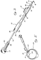
- Fig. 1 is a front side view, in perspective, of an apparatus in accordance with the present invention with the load chamber in the opened position.
- Fig. 2 is a front side view, in perspective, of the apparatus shown in Fig. 1 with the load chamber in the closed position.
- Fig. 3 is a front side view, in perspective, of the apparatus shown in Fig. 2 loaded into a hand piece.
- Fig. 4 is a side view, partly in cross-section, taken generally along line 4-4 of Fig. 3.
- Fig. 5 is a somewhat schematic illustration showing the apparatus shown in Fig. 3, with the hand piece partially in cross-section, being used to insert an IOL into an eye.
- Fig. 1 shows an IOL inserter, shown generally at 10, including a load chamber 12 and an injection tube 14.
- Inserter 10 is an integrally formed, for example, molded, unit made of polymeric material, such as polypropylene or the like materials.
- Load chamber 12 includes a first member 16 and a second member 18 which are secured or joined together and are hingeably moveable relative to each other along line 20, which is parallel to the longitudinal axis 30 of inserter 10.
- Injection tube 14 includes a proximal end portion 22, a distal end portion 24 and an open distal end 26.
- a reinforcing collar 28 is coincidental with the proximal end portion 22 of injection tube 14.
- Open distal end 26 is beveled at an angle of about 45° relative to the longitudinal axis 30 of the inserter 10.
- Injection tube 14 includes a through slot 32 which extends from the open distal end 26 distally and terminates prior to the proximal end portion 22 of injection tube 14.
- Through slot 32 is elongated in a direction parallel to the longitudinal axis 30 of inserter 10.
- inserter 10 is in the opened position.
- inserter 10 is shown in the closed position.
- the load chamber 12 includes a top 33 which is a combination of top surfaces 34 and 36 of first wing 38 and second wing 40, respectively, of first member 16 and second member 18, respectively.
- First and second wings 38 and 40 are effective for a human user of inserter 10 to hold and manipulate the inserter 10 while using it, as described hereinafter.
- Inserter 10 is described in more detail with reference to Fig. 4, which shows the inserter in combination with hand piece 70.
- the load chamber 12 of inserter 10 When used in combination with hand piece 70, the load chamber 12 of inserter 10 is in the closed position, as shown in Fig. 2. With the load chamber 12 in the closed position, and top 32 being the uppermost portion of the load chamber, open distal end 26 of injection tube 14 is beveled at an angle of 45° relative to the longitudinal axis 30 of the inserter 10 so that the open distal end is generally right facing (when the inserter is viewed from above). In addition, through slot 32 intersects the open distal end 26 at the proximal most portion of the open distal end, as shown in Figs. 1, 2 and 4.
- the load chamber defines a first lumen 52 which is elongated in a direction parallel to the longitudinal axis 30 of inserter 10.
- Injection tube 14 defines a distally tapering second lumen 54.
- the average cross-sectional area of second lumen 54 transverse to the longitudinal axis 30 is smaller than or reduced relative to the average cross-sectional area of the first lumen 52.
- the reinforcing collar 28, which is coincidental with the proximal end portion 22 of injection tube 14, has sufficient wall thickness so that the proximal end portion of the injection tube has a larger or greater wall thickness than the distal end portion 24 of the injection tube.
- the first lumen 52 is aligned with the second lumen 54 so that a folded IOL in the first lumen can be passed directly from the first lumen into the second lumen.
- the proximal portion 58 of the second lumen 54 is defined by the proximal end portion 22 of the injection tube 14.
- This proximal portion 58 of second lumen 54 has a tapering cross-sectional area transverse to the longitudinal axis 30 of the inserter 10, with the cross-sectional area decreasing in the distal direction.
- the taper of proximal portion 58 is more severe than the slight taper which exists in the distal portion 60 of the second lumen 54.
- the more severe taper in the proximal portion 58 is effective to further fold the IOL as the IOL is passed into the second lumen 54. This further folding is advantageous because the further folded IOL can be inserted into the eye through a smaller incision.
- the reinforcing collar 28 and the increased wall thickness of the proximal end portion 22 of injection tube 14 adds
- Hand piece 70 includes a relatively large, elongated first through opening 74 and a relatively small, elongated second through opening 76.
- Hand piece 70 includes a through bore 78 which extends from the proximal end 80 to the distal end 82 of the hand piece.
- the proximal end portion 84 of hand piece 70 includes threads 86 which are adapted to engage and mate with threads 88 of the proximal segment 90 of push rod member 72.
- Rod element 92 of push rod member 72 is adapted to pass through bore 78, first lumen 52, second lumen 54 and out of open distal end 26.
- Hand piece 70 and push rod member 72 are made of metal, such as surgical grade stainless steel or the like metals.
- Inserter 10 is operated and functions as follows.
- the inserter When it is desired to load an IOL into inserter 10, the inserter is placed, for example, manually placed, in a configuration as shown in Fig. 1.
- an IOL such as is shown generally at 100, is placed, for example, using forceps, in between first and second members 16 and 18. This placement is such that the anterior face 102 of optic 104 faces upwardly, as shown in Fig. 1.
- the filament haptics 106 and 108 of IOL 100 are located as shown in Fig. 1, so that the fixation members are located generally parallel to, rather than transverse to, the longitudinal axis 30.
- first and second members 16 and 18 are hingeably moved relative to each other, for example, by manually bringing first and second wings 38 and 40 together, to place the load chamber 12 in the closed position, as shown in Fig. 2.
- load chamber 12 With load chamber 12 in the closed position, IOL 100 is in a folded state, that is optic 104 is folded.
- the relative movement of first and second members 16 and 18 to move the load chamber from the open position to the closed position is effective to fold the lens.
- the folded IOL 100 is now located in the first lumen 52. For clarity sake, the folded IOL is not shown in any of Figs. 2, 3, 4 or 5.
- the inserter 10 With the inserter 10 configured as shown in Fig. 2 and folded IOL 100 located in first lumen 52, the inserter 10 is placed in association with hand piece 70, as shown in Fig. 3. In this configuration, the distal end portion 24 of injection tube 14 extends distally beyond the distal end 82 of hand piece 70. As shown in Fig. 4, the distal portion 85 of hand piece 70 includes an inner wall 87 which is configured to receive reinforcing collar 28 in abutting relation.
- This abutting contact between hand piece 70 and reinforcing collar 28 adds to the apparent strength of the injection tube 14 so that folded IOL 100 can be passed from the first lumen 52 into the second lumen 54 (so that the folded IOL 100 can be further folded so as to be inserted into the eye through a smaller incision), through the second lumen and out of the open distal end 26 without breaking, bursting or otherwise distorting the configuration of the injection tube.
- push rod member 72 With inserter 10 so placed relative to hand piece 70, push rod member 72 is placed into the through bore 78 of the hand piece starting at the proximal end 80. As threads 88 come in contact with and engage threads 86, the push rod member 72 is rotated, as shown in Fig. 5, so as to thread the push rod member onto the proximal end portion 84 of hand piece 70. By gradually moving push rod element 92 through bore 78 of hand piece 70, the folded IOL 100 is urged to move from first lumen 52 into second lumen 56, through open distal end 26 and into the eye.
- the IOL 100 is to be placed in eye 120 into an area formerly occupied by the natural lens of the eye.
- Fig. 5 shows the sclera 122 having an incision through which the distal end portion 24 of injection tube 14 is passed. Alternately, the incision can be made through the cornea. Distal end portion 24 has a sufficiently small cross-section to pass into the eye 122 through a 3.0 mm incision in the sclera 122.
- the injection tube 14 is manipulated within eye 122 until it is positioned so that IOL 100 can be properly positioned in eye 122, that is in the anterior chamber, the posterior chamber, the capsular bag 124 or in the sulcus, after being released.
- the surgeon is able to controllably position the distal end portion 24 of injection tube 14, with IOL 100 in the first lumen 52 of load chamber 12.
- the rod element 92 is urged distally, by rotating (threading) push rod member 72 onto hand piece 70, to pass the IOL 100 into and through the second lumen 54, through the open distal end 26 of injection tube 14 and into the eye 120.
- the anterior face 102 of IOL 100 faces generally forwardly in the eye 120 as the IOL is released from the inserter 10. In other words, the IOL 100 passes through first lumen 52, second lumen 54 and open distal end 26 and into eye 120 without flipping or otherwise becoming mispositioned. Only a relatively small amount of, if any, post-insertion re-positioning is needed to properly position IOL 100 in eye 120.
- the rod element 92 is moved proximally into the injection tube 14 and the distal end portion 24 of the injection tube is removed from the eye. If needed, the IOL 100 can be re-positioned in the eye by a small, bent needle or similar tool inserted into the same incision.
- the use of the present insertion apparatus reduces or minimizes the need for post-insertion manipulation of IOL 100.
- the incision in the sclera may be mended, for example, using conventional techniques.
- inserter 10 is preferably disposed of.
- Hand piece 70 and push rod member 72 can be reused, after sterilization/disinfection.
- the present IOL insertion apparatus and methods are straightforward and easy to use and practice.
- the present invention provides for an effective and controlled insertion of foldable IOLs into eyes.
- the present system very conveniently provides for precise positioning of the IOL in the eye and controlled IOL release so as to reduce, or even eliminate, the risk of damaging the eye as a result of IOL insertion or post surgical manipulation to properly position the IOL in the eye. It is to be understood that the invention is not limited thereto and that it can be variously practiced within the scope of the following claims.
Claims (9)
- Einsatzvorrichtung (10) zum Einsetzen einer faltbaren Intraokularlinse (100) in das Auge (120) eines Patienten mit den folgenden Merkmalen:dadurch gekennzeichnet, dass der proximale Endabschnitt (22) des Einsatzrohres (14) vollständig innerhalb des Handstückes (70) in Verstärkungsberührung mit diesem liegt und ein Abschnitt des distalen Endabschnitts (24) des Einsatzrohres (14) innerhalb des Handstückes (70) angeordnet ist und ein weiterer Abschnitt distal von dem Handstück (70) vorsteht;eine Beschickungskammer (12) definiert ein erstes Lumen (52) und dient dazu, eine Intraokularlinse aufzunehmen und die Intraokularlinse (100) im Faltzustand zu halten, wenn die Intraokularlinse (100) im ersten Lumen (52) angeordnet ist;ein Einsatzrohr (14) definiert ein zweites Lumen (54), das auf das erste Lumen (52) ausgerichtet ist und dazu dient, die gefaltete Intraokularlinse (100) aus dem ersten Lumen (52) aufzunehmen, wobei das Einsatzrohr (14) einen proximalen Endabschnitt (22) mit einer Wandstärke, einen distalen Endabschnitt (24) mit einer Wandstärke und ein offenes distales Ende aufweist, das mit dem Lumen (54) in Verbindung steht und durch das die gefaltete Intraokularlinse (100) aus dem zweiten Lumen (54) hindurchtritt, um in ein Auge eingesetzt zu werden, wobei die Wandstärke des proximalen Endabschnitts (22) größer ist als die Wandstärke des distalen Endabschnitts (24);ein Handstück (70) dient dazu, in der Hand des Benutzers gehalten zu werden, der die Einsatzvorrichtung (10) benutzt, um eine Intraokularlinse (100) in ein Auge einzusetzen, wobei das Handstück (70) eine Bohrung (78) mit einer Öffnung aufweist, die die Beschickungskammer (12) aufnimmt,
wobei der proximale Endabschnitt (22) des Einsatzrohres (14) an dem Handstück (70) anstößt und diese Anstoßbewegung als Anschlag für die Vorwärtsbewegung des proximalen Endabschnitts (22) in distaler Richtung wirkt. - Einsatzvorrichtung (10) nach Anspruch 1, bei welcher das zweite Lumen (54) eine kleinere durchschnittliche Querschnittsfläche besitzt als das erste Lumen (52).
- Einsatzvorrichtung (10) nach Anspruch 1, bei welcher die Beschickungskammer (12) und das Einsatzrohr (14) aus Polymermaterial bestehen und das Handstück (70) aus Metall gefertigt ist und wobei weiter eine Schubstange (72) vorgesehen ist, die so bemessen und angeordnet ist, dass sie durch die Bohrung (78) durch das erste Lumen (52) und wenigstens einen Teil des zweiten Lumen (54) hindurchtreten kann, um eine Intraokularlinse (100) von dem ersten Lumen (52) durch das zweite Lumen (54) und in ein Auge (120) hinein zu verschieben.
- Einsatzvorrichtung (10) nach Anspruch 3, bei welcher das Handstück (70) und die Schubstange (72) Segmente mit gegenseitig in Eingriff stehenden Gewinden (86, 88) aufweisen, so dass die Schubstange (72) in das Handstück (70) eingeschraubt werden kann, um die Schubstange (72) durch die Bohrung (78) vorzuschieben.
- Einsatzvorrichtung (10) nach Anspruch 1, bei welcher das offene distale Ende (26) abgeschrägt ist.
- Einsatzvorrichtung (10) nach Anspruch 5, bei welcher die Beschickungskammer (12) eine Oberseite (33) aufweist und das offene distale Ende (26) derart abgeschrägt ist, dass das offene distale Ende (26) allgemein nach rechts weist, wenn die Vorrichtung von der Oberseite (33) her betrachtet wird und der distale Endabschnitt (24) sich distal weg erstreckt.
- Einsatzvorrichtung (10) nach Anspruch 5, bei welcher das Einsatzrohr (14) weiter einen Durchgangsschlitz (32) aufweist, der sich über das offene distale Ende (26) erstreckt und distal gegenüber dem proximalen Endabschnitt (22) des Einsatzrohres (14) endet und das offene distale Ende (26) an dem proximal größten Abschnitt des offenen distalen Endes (26) oder in der Nähe hiervon durchschneidet.
- Einsatzvorrichtung (10) nach Anspruch 1, bei welcher die Beschickungskammer (12) erste und zweite Glieder (16, 18) aufweist, die relativ zueinander beweglich sind, um die Beschickungskammer (12) in eine Öffnungsstellung oder eine Schließstellung zu überführen, wobei die ersten und zweiten Glieder (16, 18) so bemessen und angeordnet sind, dass sie eine Intraokularlinse (100) im ungefalteten Zustand zwischen dem ersten und zweiten Glied (16, 18) aufnehmen, wenn die Beschickungskammer (12) in die Öffnungsstellung überführt ist und die die Intraokularlinse (100) in einen Faltzustand überführen, wenn wenigstens eines der ersten und zweiten Glieder (16, 18) bewegt wird, um die Beschickungskammer (12) in Schließstellung zu überführen.
- Einsatzvorrichtung (10) nach Anspruch 8, bei welchem das erste und das zweite Glied (16, 18) relativ zueinander schwenkbar beweglich sind.
Applications Claiming Priority (3)
| Application Number | Priority Date | Filing Date | Title |
|---|---|---|---|
| US08/323,172 US5582613A (en) | 1993-11-18 | 1994-10-14 | Apparatus and methods for controlled insertion of intraocular lenses |
| US323172 | 1994-10-14 | ||
| EP95935715A EP0785760B1 (de) | 1994-10-14 | 1995-10-14 | Vorrichtung zum kontrollierten einsetzen einer intraokularlinse |
Related Parent Applications (1)
| Application Number | Title | Priority Date | Filing Date |
|---|---|---|---|
| EP95935715A Division EP0785760B1 (de) | 1994-10-14 | 1995-10-14 | Vorrichtung zum kontrollierten einsetzen einer intraokularlinse |
Publications (2)
| Publication Number | Publication Date |
|---|---|
| EP1023880A1 EP1023880A1 (de) | 2000-08-02 |
| EP1023880B1 true EP1023880B1 (de) | 2003-10-01 |
Family
ID=23258027
Family Applications (2)
| Application Number | Title | Priority Date | Filing Date |
|---|---|---|---|
| EP00201469A Expired - Lifetime EP1023880B1 (de) | 1994-10-14 | 1995-10-14 | Vorrichtung zum kontrollierten Einsetzen einer Intraokularlinse |
| EP95935715A Expired - Lifetime EP0785760B1 (de) | 1994-10-14 | 1995-10-14 | Vorrichtung zum kontrollierten einsetzen einer intraokularlinse |
Family Applications After (1)
| Application Number | Title | Priority Date | Filing Date |
|---|---|---|---|
| EP95935715A Expired - Lifetime EP0785760B1 (de) | 1994-10-14 | 1995-10-14 | Vorrichtung zum kontrollierten einsetzen einer intraokularlinse |
Country Status (6)
| Country | Link |
|---|---|
| US (1) | US5582613A (de) |
| EP (2) | EP1023880B1 (de) |
| JP (1) | JPH10512460A (de) |
| AU (1) | AU3762995A (de) |
| DE (2) | DE69519587T2 (de) |
| WO (1) | WO1996011649A1 (de) |
Cited By (2)
| Publication number | Priority date | Publication date | Assignee | Title |
|---|---|---|---|---|
| US7901414B2 (en) | 2001-12-12 | 2011-03-08 | Ioltechnologie-Production | Cassette and injector for flexible intraocular lens and method for injecting such lenses |
| US10722346B2 (en) | 2017-09-19 | 2020-07-28 | Bausch & Lomb Incorporated | Intraocular lens injector assembly having shuttle assembly retaining intraocular lens in storage vial and operably presenting intraocular lens in injector assembly |
Families Citing this family (61)
| Publication number | Priority date | Publication date | Assignee | Title |
|---|---|---|---|---|
| DK0723429T3 (da) * | 1992-09-30 | 2002-07-29 | Vladimir Feingold | Intraokulært linseindsættelsessystem |
| US5653715A (en) | 1993-03-09 | 1997-08-05 | Chiron Vision Corporation | Apparatus for preparing an intraocular lens for insertion |
| JP3704154B2 (ja) * | 1994-11-18 | 2005-10-05 | スター サージカル カンパニー | 眼内レンズ挿入システム |
| US5766181A (en) * | 1996-08-02 | 1998-06-16 | Staar Surgical Company, Inc. | Spring biased deformable intraocular injecting apparatus |
| US5876406A (en) * | 1996-08-02 | 1999-03-02 | Staar Surgical Company, Inc. | Deformable intraocular lens injecting apparatus with transverse hinged lens cartridge |
| US5944725A (en) | 1996-09-26 | 1999-08-31 | Bausch & Lomb Surgical, Inc. | Method and apparatus for inserting a flexible membrane into an eye |
| US6179843B1 (en) | 1997-06-28 | 2001-01-30 | Harold H. Weiler | Device for insertion of foldable intraocular lenses |
| AU7361898A (en) | 1997-10-24 | 1999-05-17 | Tekia, Inc. | Ophthalmologic insertor apparatus and methods of use |
| US6605093B1 (en) | 1997-10-24 | 2003-08-12 | Tekia, Inc. | Device and method for use with an ophthalmologic insertor apparatus |
| US5921989A (en) * | 1998-02-12 | 1999-07-13 | Allergan | Lens protector for intraocular lens inserter |
| US6371960B2 (en) | 1998-05-19 | 2002-04-16 | Bausch & Lomb Surgical, Inc. | Device for inserting a flexible intraocular lens |
| FR2820633B1 (fr) * | 2001-02-13 | 2003-08-15 | Biotech | Dispositif et procede d'injection de lentille intraoculaire |
| EP1434541A2 (de) * | 2001-10-12 | 2004-07-07 | Humanoptics AG | Vorrichtung zum falten einer intraokularlinse sowie aufbewahrungssystem für eine intraokularlinse |
| DE10164420A1 (de) * | 2001-10-12 | 2003-07-17 | Humanoptics Ag | Vorrichtung zum Falten einer Intraokularlinse sowie Aufbewahrungssystem für eine Intraokularlinse |
| US20040059343A1 (en) * | 2002-09-25 | 2004-03-25 | Kevin Shearer | Novel enhanced system for intraocular lens insertion |
| US20040147938A1 (en) * | 2002-09-25 | 2004-07-29 | Microsurgical Technology | System for IOL insertion |
| DE202004017931U1 (de) | 2004-08-12 | 2005-01-13 | Medicel Ag | Vorrichtung zum Beladen einer Linsenfaltkartusche mit einer intraokularen Linse, sowie Linsenfaltkartusche und Set für die Implantation |
| US20060085013A1 (en) * | 2004-10-20 | 2006-04-20 | Vaclav Dusek | Intraocular lens inserter |
| EP1832247B1 (de) | 2004-12-27 | 2015-06-24 | Hoya Corporation | Vorrichtung zur implantation einer intraokularlinse |
| US20060167466A1 (en) * | 2005-01-21 | 2006-07-27 | Vaclav Dusek | Intraocular lens inserter system components |
| JP5221949B2 (ja) | 2005-01-26 | 2013-06-26 | Hoya株式会社 | 眼内レンズ挿入用器具 |
| JP4836046B2 (ja) | 2005-02-24 | 2011-12-14 | Hoya株式会社 | 眼内レンズ挿入器具 |
| US7892283B2 (en) * | 2005-04-08 | 2011-02-22 | Abbott Medical Optics Inc. | Methods and apparatus for inserting an intraocular lens into an eye |
| US7892282B2 (en) * | 2005-04-08 | 2011-02-22 | Abbott Medical Optics Inc. | Methods and apparatus for inserting an intraocular lens into an eye |
| US8053078B2 (en) | 2005-04-11 | 2011-11-08 | Abbott Medical Optics Inc. | Medical devices having soft, flexible lubricious coatings |
| WO2007037223A1 (ja) | 2005-09-28 | 2007-04-05 | Hoya Corporation | 眼内レンズ挿入用器具 |
| US20070078466A1 (en) * | 2005-09-30 | 2007-04-05 | Restoration Robotics, Inc. | Methods for harvesting follicular units using an automated system |
| JP4877643B2 (ja) | 2005-12-08 | 2012-02-15 | Hoya株式会社 | 眼内レンズ挿入用器具 |
| EP2111820A1 (de) | 2007-01-17 | 2009-10-28 | Ajl, S.a. | Behälter für eine intraokularlinse und verfahren zum anbringen einer intraokularlinse |
| US20080255577A1 (en) * | 2007-04-11 | 2008-10-16 | Downer David A | Lens Delivery System Cartridge and Method of Manufacture |
| EP2161005B1 (de) | 2007-05-30 | 2016-12-28 | Hoya Corporation | Instrument zum einsetzen einer intraokularlinse |
| EP2161004B1 (de) | 2007-05-30 | 2017-12-27 | Hoya Corporation | Instrument zum einsetzen einer intraokularlinse |
| JP5086713B2 (ja) | 2007-07-11 | 2012-11-28 | Hoya株式会社 | 眼内レンズ挿入器具 |
| US8968396B2 (en) | 2007-07-23 | 2015-03-03 | Powervision, Inc. | Intraocular lens delivery systems and methods of use |
| EP2647353B1 (de) | 2007-07-23 | 2014-12-31 | PowerVision, Inc. | Linseneinführsystem |
| JP5330401B2 (ja) | 2007-11-08 | 2013-10-30 | アリメラ・サイエンシーズ,インコーポレーテッド | 眼のための埋め込み装置、及びその装置を備えるキット |
| US8894664B2 (en) | 2008-02-07 | 2014-11-25 | Novartis Ag | Lens delivery system cartridge |
| JP5254669B2 (ja) | 2008-06-05 | 2013-08-07 | Hoya株式会社 | 眼内レンズ挿入器具及びカートリッジ |
| JP5470753B2 (ja) | 2008-06-17 | 2014-04-16 | Hoya株式会社 | 眼内レンズ挿入器具 |
| JP5323420B2 (ja) | 2008-08-21 | 2013-10-23 | Hoya株式会社 | 眼内レンズ挿入器具 |
| JP5416379B2 (ja) | 2008-09-04 | 2014-02-12 | Hoya株式会社 | 眼内レンズ挿入器具 |
| US8801780B2 (en) | 2008-10-13 | 2014-08-12 | Alcon Research, Ltd. | Plunger tip coupling device for intraocular lens injector |
| WO2010079780A1 (ja) | 2009-01-07 | 2010-07-15 | Hoya株式会社 | 眼内レンズ挿入器具 |
| MX2011008381A (es) | 2009-02-11 | 2011-09-06 | Alcon Res Ltd | Dispositivo inyector de lentes intraoculares automatico. |
| EP2555708B1 (de) | 2010-04-08 | 2015-03-18 | Hoya Corporation | Vorrichtung zum einsetzen eines augenimplantats |
| JP5511530B2 (ja) | 2010-06-10 | 2014-06-04 | Hoya株式会社 | 眼内レンズ挿入装置 |
| WO2012006616A2 (en) | 2010-07-09 | 2012-01-12 | Powervision, Inc. | Intraocular lens delivery devices and methods of use |
| JP6071995B2 (ja) | 2011-03-24 | 2017-02-01 | パワーヴィジョン・インコーポレーテッド | 眼内レンズ装填システムおよび使用方法 |
| AU2013271703B2 (en) | 2012-06-04 | 2017-05-11 | Alcon Inc. | Intraocular lens inserter |
| CN104619285B (zh) | 2012-06-12 | 2018-05-01 | 奥特威资有限责任公司 | 眼内气体注射器 |
| EP3785668A1 (de) | 2013-03-15 | 2021-03-03 | Alcon Inc. | Aufbewahrungs- und ladevorrichtung für intraokularlinsen und verfahren zur verwendung |
| US20140303636A1 (en) * | 2013-04-09 | 2014-10-09 | Bausch & Lomb Incorporated | Intraocular Lens Injector Cartridge Providing Lens Control |
| DE102013105185B4 (de) * | 2013-05-21 | 2017-01-05 | Carl Zeiss Meditec Ag | Kassette zur Aufnahme einer Intraokularlinse, Injektorvorrichtung mit einer Kassette und Verfahren zum Falten einer Intraokularlinse in einer Kassette |
| WO2015154049A1 (en) | 2014-04-04 | 2015-10-08 | Altaviz, Llc | Intraocular lens inserter |
| US9451982B1 (en) | 2015-06-06 | 2016-09-27 | Coloplast A/S | System for implanting a penile prosthetic into a penis includes a delivery cap coupled to a tow suture |
| JP6646987B2 (ja) | 2015-09-16 | 2020-02-14 | Hoya株式会社 | 眼内レンズ挿入器具 |
| US10849738B2 (en) | 2015-09-16 | 2020-12-01 | Hoya Corporation | Intraocular lens injector |
| US10172706B2 (en) | 2015-10-31 | 2019-01-08 | Novartis Ag | Intraocular lens inserter |
| SG11201811530UA (en) | 2016-06-28 | 2019-01-30 | Hoya Corp | Intraocular lens injector |
| US11000367B2 (en) | 2017-01-13 | 2021-05-11 | Alcon Inc. | Intraocular lens injector |
| US11224537B2 (en) | 2018-10-19 | 2022-01-18 | Alcon Inc. | Intraocular gas injector |
Family Cites Families (61)
| Publication number | Priority date | Publication date | Assignee | Title |
|---|---|---|---|---|
| US450266A (en) * | 1891-04-14 | Surgical instrument | ||
| US2450138A (en) * | 1945-10-05 | 1948-09-28 | Int Cellucotton Products | Tampon applicator |
| US3678927A (en) * | 1968-03-18 | 1972-07-25 | Samuel Soichet | Intra uterine device and injector thereof |
| US3703174A (en) * | 1970-07-14 | 1972-11-21 | Medidyne Corp | Method and apparatus for catheter injection |
| US4026281A (en) * | 1973-10-12 | 1977-05-31 | Ortho Pharmaceutical Corporation | Method and apparatus for inserting an intrauterine contraceptive device |
| US4198980A (en) * | 1976-10-29 | 1980-04-22 | Bausch & Lomb Incorporated | Intraocular lens inserting tool |
| US4122556A (en) * | 1977-03-23 | 1978-10-31 | Stanley Poler | Intra-ocular lens |
| US4190049A (en) * | 1977-08-08 | 1980-02-26 | Hager Clarence L | Posterior lens implant tool |
| US4214585A (en) * | 1978-05-15 | 1980-07-29 | Bailey Paul F Jr | Tool for surgical implantation of an intraocular lens |
| US4253199A (en) * | 1978-09-25 | 1981-03-03 | Surgical Design Corporation | Surgical method and apparatus for implants for the eye |
| US4244370A (en) * | 1978-11-20 | 1981-01-13 | American Medical Systems, Inc. | Tool for positioning implantable medical prosthetic device _and method of using same |
| US4251887A (en) * | 1979-04-02 | 1981-02-24 | Anis Aziz Y | Posterior chamber capsular lens implant and method for implantation of the lens |
| US4249271A (en) * | 1979-07-13 | 1981-02-10 | Stanley Poler | Intraocular lens |
| US4298994A (en) * | 1979-10-26 | 1981-11-10 | Clayman Henry M | Posterior chamber intra-ocular transplant device |
| US4257521A (en) * | 1979-11-16 | 1981-03-24 | Stanley Poler | Packaging means for an intraocular lens |
| US4325375A (en) * | 1980-05-12 | 1982-04-20 | Nevyas Herbert J | Instrument for inserting and removing intraocular lens |
| US4303268A (en) * | 1980-05-22 | 1981-12-01 | Davidson Harvey D | Method and apparatus for removing embedded ticks |
| BR8108867A (pt) * | 1980-11-13 | 1982-10-13 | Harry H Leveen | Pinca de lente intraocular |
| US4373218A (en) * | 1980-11-17 | 1983-02-15 | Schachar Ronald A | Variable power intraocular lens and method of implanting into the posterior chamber |
| DE3103352C2 (de) * | 1981-01-31 | 1982-10-21 | Aesculap-Werke Ag Vormals Jetter & Scheerer, 7200 Tuttlingen | Pinzetten- oder zangenförmiges chirurgisches Instrument |
| US4446581A (en) * | 1981-09-02 | 1984-05-08 | Blake L W | Intraocular lens with free-ended sizing prong |
| US4490860A (en) * | 1982-01-18 | 1985-01-01 | Ioptex Inc. | Intraocular lens apparatus and method for implantation of same |
| US4423809A (en) * | 1982-02-05 | 1984-01-03 | Staar Surgical Company, Inc. | Packaging system for intraocular lens structures |
| US4573998A (en) * | 1982-02-05 | 1986-03-04 | Staar Surgical Co. | Methods for implantation of deformable intraocular lenses |
| US4449257A (en) * | 1982-05-03 | 1984-05-22 | Barnes-Hind/Hydrocurve, Inc. | Intraocular lens and method of retaining in place |
| US4468820A (en) * | 1982-05-10 | 1984-09-04 | Precision-Cosmet Co., Inc. | Haptic attachment for intraocular lenses |
| US4600004A (en) * | 1982-09-08 | 1986-07-15 | Osvaldo Lopez | Intraocular lens holder and inserter |
| US4463457A (en) * | 1982-09-24 | 1984-08-07 | Kelman Charles D | Intraocular lens and method of positioning the same in an eye |
| US4527294A (en) * | 1983-12-16 | 1985-07-09 | Heslin K B | Intraocular lens construction |
| US4732150A (en) * | 1984-06-14 | 1988-03-22 | Keener Jr Gerald T | Process for cataract extraction |
| JPS61122856A (ja) * | 1984-09-07 | 1986-06-10 | プレシジョン−コスメット カンパニ−,インコ−ポレイティド | 眼内レンズ構造物 |
| US4681102A (en) * | 1985-09-11 | 1987-07-21 | Bartell Michael T | Apparatus and method for insertion of an intra-ocular lens |
| US4715373A (en) * | 1985-09-27 | 1987-12-29 | Mazzocco Thomas R | Devices for implantation of deformable intraocular lens structures |
| DE3618193A1 (de) * | 1986-05-30 | 1987-12-03 | Detlef Dr Uthoff | Vorrichtung zum aufnehmen, halten und manipulieren von gegenstaenden im medizinischen bereich |
| US4785810A (en) * | 1986-10-14 | 1988-11-22 | Storz Instrument Company | Intraocular lens folding and insertion apparatus |
| US4919130A (en) * | 1986-11-07 | 1990-04-24 | Nestle S.A. | Tool for inserting compressible intraocular lenses into the eye and method |
| US4747404A (en) * | 1986-11-10 | 1988-05-31 | Kresge Eye Institute Of Wayne State University | Foldable intraocular lens inserter |
| US4763650A (en) * | 1987-01-20 | 1988-08-16 | Hauser Stephen G | Instrument for inserting a deformable lens into the eye |
| US4819631A (en) * | 1987-03-26 | 1989-04-11 | Poley Brooks J | Folded intraocular lens, method of implanting it, retainer, and apparatus for folding lens |
| US4769034A (en) * | 1987-03-26 | 1988-09-06 | Poley Brooks J | Folded intraocular lens, method of implanting folded intraocular lens |
| US4917680A (en) * | 1988-06-30 | 1990-04-17 | Poley Brooks J | Folded intraocular lens with endless band retainer |
| US4988352A (en) * | 1987-03-26 | 1991-01-29 | Poley Brooks J | Method and apparatus for folding, freezing and implanting intraocular lens |
| US4813957A (en) * | 1987-04-27 | 1989-03-21 | Mcdonald Henry H | Intraocular lens implantation |
| US4791924A (en) * | 1987-06-02 | 1988-12-20 | Kelman Charles D | Lens forceps and method of use thereof |
| US4781719A (en) * | 1987-07-28 | 1988-11-01 | Kelman Charles D | Method of inserting an intraocular lens into an eye |
| US4759359A (en) * | 1987-08-31 | 1988-07-26 | Allergan, Inc. | Lens implantation instrument |
| US4834094A (en) * | 1987-10-07 | 1989-05-30 | Patton Medical Technologies, Inc. | "Canoe" apparatus for inserting intra-ocular lens into the eye |
| US4765329A (en) * | 1987-10-19 | 1988-08-23 | Cumming, Redwitz & Wilson, Inc. | Intraocular lens insertion instrument |
| US4844065A (en) * | 1987-11-06 | 1989-07-04 | Faulkner Gerald D | Intraocular lens inserting tool and method |
| US4844093A (en) * | 1987-11-30 | 1989-07-04 | Kresge Eye Institute | Tool for folding and inserting intraocular lenses |
| US4934363A (en) * | 1987-12-15 | 1990-06-19 | Iolab Corporation | Lens insertion instrument |
| US4880000A (en) * | 1987-12-15 | 1989-11-14 | Iolab Corporation | Lens insertion instrument |
| US4836201A (en) * | 1988-03-24 | 1989-06-06 | Patton Medical Technologies, Inc. | "Envelope" apparatus for inserting intra-ocular lens into the eye |
| US4976716A (en) * | 1989-01-23 | 1990-12-11 | Cumming J Stuart | Intraocular lens insertion device |
| US5098439A (en) * | 1989-04-12 | 1992-03-24 | Allergan, Inc. | Small incision intraocular lens insertion apparatus |
| US5123905A (en) * | 1991-06-07 | 1992-06-23 | Kelman Charles D | Intraocular lens injector |
| US5190552A (en) * | 1992-02-04 | 1993-03-02 | Kelman Charles D | Slotted tube injector for an intraocular lens |
| US5260021A (en) * | 1992-06-29 | 1993-11-09 | Allergan, Inc. | Hydrogen peroxide-containing gels and contact lens disinfecting using same |
| DK0723429T3 (da) * | 1992-09-30 | 2002-07-29 | Vladimir Feingold | Intraokulært linseindsættelsessystem |
| US5653715A (en) * | 1993-03-09 | 1997-08-05 | Chiron Vision Corporation | Apparatus for preparing an intraocular lens for insertion |
| US5425734A (en) * | 1993-07-02 | 1995-06-20 | Iovision, Inc. | Intraocular lens injector |
-
1994
- 1994-10-14 US US08/323,172 patent/US5582613A/en not_active Expired - Fee Related
-
1995
- 1995-10-14 EP EP00201469A patent/EP1023880B1/de not_active Expired - Lifetime
- 1995-10-14 DE DE69519587T patent/DE69519587T2/de not_active Expired - Fee Related
- 1995-10-14 AU AU37629/95A patent/AU3762995A/en not_active Abandoned
- 1995-10-14 JP JP8513285A patent/JPH10512460A/ja not_active Ceased
- 1995-10-14 EP EP95935715A patent/EP0785760B1/de not_active Expired - Lifetime
- 1995-10-14 WO PCT/US1995/012735 patent/WO1996011649A1/en active IP Right Grant
- 1995-10-14 DE DE69531878T patent/DE69531878T2/de not_active Expired - Fee Related
Cited By (2)
| Publication number | Priority date | Publication date | Assignee | Title |
|---|---|---|---|---|
| US7901414B2 (en) | 2001-12-12 | 2011-03-08 | Ioltechnologie-Production | Cassette and injector for flexible intraocular lens and method for injecting such lenses |
| US10722346B2 (en) | 2017-09-19 | 2020-07-28 | Bausch & Lomb Incorporated | Intraocular lens injector assembly having shuttle assembly retaining intraocular lens in storage vial and operably presenting intraocular lens in injector assembly |
Also Published As
| Publication number | Publication date |
|---|---|
| EP1023880A1 (de) | 2000-08-02 |
| WO1996011649A1 (en) | 1996-04-25 |
| EP0785760A1 (de) | 1997-07-30 |
| AU3762995A (en) | 1996-05-06 |
| JPH10512460A (ja) | 1998-12-02 |
| DE69531878T2 (de) | 2004-05-19 |
| DE69519587T2 (de) | 2001-05-31 |
| DE69519587D1 (de) | 2001-01-11 |
| US5582613A (en) | 1996-12-10 |
| DE69531878D1 (de) | 2003-11-06 |
| EP0785760B1 (de) | 2000-12-06 |
Similar Documents
| Publication | Publication Date | Title |
|---|---|---|
| EP1023880B1 (de) | Vorrichtung zum kontrollierten Einsetzen einer Intraokularlinse | |
| EP0957828B1 (de) | Vorrichtung zum einsetzen einer intraokularlinse | |
| US5562676A (en) | Deformable lens insertion apparatus and method | |
| US5584304A (en) | Method of inserting an IOL using a forceps inside a folding tube | |
| US6267768B1 (en) | Lens protector for intraocular lens inserter | |
| US6251114B1 (en) | Rotatable IOL insertion apparatus and method for using same | |
| US6923815B2 (en) | Intraocular lens insertion apparatus | |
| US6334862B1 (en) | Apparatus and methods for IOL insertion | |
| US6093193A (en) | IOL insertion apparatus and method for using same | |
| CA2436156C (en) | Apparatus and method for multiply folding and inserting an intraocular lens in an eye | |
| AU692425B2 (en) | A lens cartridge for use in a surgical lens inserting device | |
| JP2009285495A (ja) | 眼内レンズの操作方法および装置 | |
| WO2000049975A1 (en) | Lens protector for intraocular lens inserter | |
| AU2002237939A1 (en) | Apparatus and method for multiply folding and inserting an intraocular lens in an eye |
Legal Events
| Date | Code | Title | Description |
|---|---|---|---|
| PUAI | Public reference made under article 153(3) epc to a published international application that has entered the european phase |
Free format text: ORIGINAL CODE: 0009012 |
|
| 17P | Request for examination filed |
Effective date: 20000518 |
|
| AC | Divisional application: reference to earlier application |
Ref document number: 785760 Country of ref document: EP |
|
| AK | Designated contracting states |
Kind code of ref document: A1 Designated state(s): CH DE FR GB IT LI NL SE |
|
| RIN1 | Information on inventor provided before grant (corrected) |
Inventor name: MCNICHOLAS, THOMAS M. Inventor name: BRADY, DANIEL G. |
|
| AKX | Designation fees paid |
Free format text: CH DE FR GB IT LI NL SE |
|
| 17Q | First examination report despatched |
Effective date: 20010831 |
|
| RAP1 | Party data changed (applicant data changed or rights of an application transferred) |
Owner name: ADVANCED MEDICAL OPTICS, INC. |
|
| GRAH | Despatch of communication of intention to grant a patent |
Free format text: ORIGINAL CODE: EPIDOS IGRA |
|
| GRAS | Grant fee paid |
Free format text: ORIGINAL CODE: EPIDOSNIGR3 |
|
| GRAA | (expected) grant |
Free format text: ORIGINAL CODE: 0009210 |
|
| AC | Divisional application: reference to earlier application |
Ref document number: 0785760 Country of ref document: EP Kind code of ref document: P |
|
| AK | Designated contracting states |
Kind code of ref document: B1 Designated state(s): CH DE FR GB IT LI NL SE |
|
| PG25 | Lapsed in a contracting state [announced via postgrant information from national office to epo] |
Ref country code: IT Free format text: LAPSE BECAUSE OF FAILURE TO SUBMIT A TRANSLATION OF THE DESCRIPTION OR TO PAY THE FEE WITHIN THE PRESCRIBED TIME-LIMIT;WARNING: LAPSES OF ITALIAN PATENTS WITH EFFECTIVE DATE BEFORE 2007 MAY HAVE OCCURRED AT ANY TIME BEFORE 2007. THE CORRECT EFFECTIVE DATE MAY BE DIFFERENT FROM THE ONE RECORDED. Effective date: 20031001 |
|
| REG | Reference to a national code |
Ref country code: GB Ref legal event code: FG4D |
|
| REG | Reference to a national code |
Ref country code: CH Ref legal event code: EP |
|
| PG25 | Lapsed in a contracting state [announced via postgrant information from national office to epo] |
Ref country code: LI Free format text: LAPSE BECAUSE OF NON-PAYMENT OF DUE FEES Effective date: 20031031 Ref country code: CH Free format text: LAPSE BECAUSE OF NON-PAYMENT OF DUE FEES Effective date: 20031031 |
|
| REF | Corresponds to: |
Ref document number: 69531878 Country of ref document: DE Date of ref document: 20031106 Kind code of ref document: P |
|
| PG25 | Lapsed in a contracting state [announced via postgrant information from national office to epo] |
Ref country code: GB Free format text: LAPSE BECAUSE OF NON-PAYMENT OF DUE FEES Effective date: 20040101 Ref country code: SE Free format text: LAPSE BECAUSE OF FAILURE TO SUBMIT A TRANSLATION OF THE DESCRIPTION OR TO PAY THE FEE WITHIN THE PRESCRIBED TIME-LIMIT Effective date: 20040101 |
|
| PG25 | Lapsed in a contracting state [announced via postgrant information from national office to epo] |
Ref country code: NL Free format text: LAPSE BECAUSE OF NON-PAYMENT OF DUE FEES Effective date: 20040501 Ref country code: DE Free format text: LAPSE BECAUSE OF NON-PAYMENT OF DUE FEES Effective date: 20040501 |
|
| ET | Fr: translation filed | ||
| REG | Reference to a national code |
Ref country code: CH Ref legal event code: PL |
|
| NLV4 | Nl: lapsed or anulled due to non-payment of the annual fee |
Effective date: 20040501 |
|
| PLBE | No opposition filed within time limit |
Free format text: ORIGINAL CODE: 0009261 |
|
| STAA | Information on the status of an ep patent application or granted ep patent |
Free format text: STATUS: NO OPPOSITION FILED WITHIN TIME LIMIT |
|
| GBPC | Gb: european patent ceased through non-payment of renewal fee |
Effective date: 20040101 |
|
| PG25 | Lapsed in a contracting state [announced via postgrant information from national office to epo] |
Ref country code: FR Free format text: LAPSE BECAUSE OF NON-PAYMENT OF DUE FEES Effective date: 20040831 |
|
| 26N | No opposition filed |
Effective date: 20040702 |
|
| REG | Reference to a national code |
Ref country code: FR Ref legal event code: ST |
|
| PG25 | Lapsed in a contracting state [announced via postgrant information from national office to epo] |
Ref country code: FR Free format text: LAPSE BECAUSE OF NON-PAYMENT OF DUE FEES Effective date: 20031031 |