EP1022425B1 - Bandanordnung für Türen, Fenster und dergleichen - Google Patents
Bandanordnung für Türen, Fenster und dergleichen Download PDFInfo
- Publication number
- EP1022425B1 EP1022425B1 EP99125075A EP99125075A EP1022425B1 EP 1022425 B1 EP1022425 B1 EP 1022425B1 EP 99125075 A EP99125075 A EP 99125075A EP 99125075 A EP99125075 A EP 99125075A EP 1022425 B1 EP1022425 B1 EP 1022425B1
- Authority
- EP
- European Patent Office
- Prior art keywords
- hinge
- sealing
- casement
- leaf
- hinge part
- Prior art date
- Legal status (The legal status is an assumption and is not a legal conclusion. Google has not performed a legal analysis and makes no representation as to the accuracy of the status listed.)
- Expired - Lifetime
Links
Images
Classifications
-
- E—FIXED CONSTRUCTIONS
- E06—DOORS, WINDOWS, SHUTTERS, OR ROLLER BLINDS IN GENERAL; LADDERS
- E06B—FIXED OR MOVABLE CLOSURES FOR OPENINGS IN BUILDINGS, VEHICLES, FENCES OR LIKE ENCLOSURES IN GENERAL, e.g. DOORS, WINDOWS, BLINDS, GATES
- E06B7/00—Special arrangements or measures in connection with doors or windows
- E06B7/16—Sealing arrangements on wings or parts co-operating with the wings
- E06B7/22—Sealing arrangements on wings or parts co-operating with the wings by means of elastic edgings, e.g. elastic rubber tubes; by means of resilient edgings, e.g. felt or plush strips, resilient metal strips
- E06B7/23—Plastic, sponge rubber, or like strips or tubes
- E06B7/2305—Plastic, sponge rubber, or like strips or tubes with an integrally formed part for fixing the edging
- E06B7/2307—Plastic, sponge rubber, or like strips or tubes with an integrally formed part for fixing the edging with a single sealing-line or -plane between the wing and the part co-operating with the wing
- E06B7/231—Plastic, sponge rubber, or like strips or tubes with an integrally formed part for fixing the edging with a single sealing-line or -plane between the wing and the part co-operating with the wing with a solid sealing part
-
- E—FIXED CONSTRUCTIONS
- E05—LOCKS; KEYS; WINDOW OR DOOR FITTINGS; SAFES
- E05D—HINGES OR SUSPENSION DEVICES FOR DOORS, WINDOWS OR WINGS
- E05D11/00—Additional features or accessories of hinges
-
- E—FIXED CONSTRUCTIONS
- E06—DOORS, WINDOWS, SHUTTERS, OR ROLLER BLINDS IN GENERAL; LADDERS
- E06B—FIXED OR MOVABLE CLOSURES FOR OPENINGS IN BUILDINGS, VEHICLES, FENCES OR LIKE ENCLOSURES IN GENERAL, e.g. DOORS, WINDOWS, BLINDS, GATES
- E06B7/00—Special arrangements or measures in connection with doors or windows
- E06B7/16—Sealing arrangements on wings or parts co-operating with the wings
- E06B7/22—Sealing arrangements on wings or parts co-operating with the wings by means of elastic edgings, e.g. elastic rubber tubes; by means of resilient edgings, e.g. felt or plush strips, resilient metal strips
-
- E—FIXED CONSTRUCTIONS
- E05—LOCKS; KEYS; WINDOW OR DOOR FITTINGS; SAFES
- E05D—HINGES OR SUSPENSION DEVICES FOR DOORS, WINDOWS OR WINGS
- E05D3/00—Hinges with pins
- E05D3/02—Hinges with pins with one pin
- E05D2003/025—Hinges with pins with one pin having three knuckles
-
- E—FIXED CONSTRUCTIONS
- E05—LOCKS; KEYS; WINDOW OR DOOR FITTINGS; SAFES
- E05D—HINGES OR SUSPENSION DEVICES FOR DOORS, WINDOWS OR WINGS
- E05D5/00—Construction of single parts, e.g. the parts for attachment
- E05D5/02—Parts for attachment, e.g. flaps
- E05D5/0215—Parts for attachment, e.g. flaps for attachment to profile members or the like
- E05D5/0223—Parts for attachment, e.g. flaps for attachment to profile members or the like with parts, e.g. screws, extending through the profile wall or engaging profile grooves
- E05D5/023—Parts for attachment, e.g. flaps for attachment to profile members or the like with parts, e.g. screws, extending through the profile wall or engaging profile grooves with parts extending through the profile wall
-
- E—FIXED CONSTRUCTIONS
- E05—LOCKS; KEYS; WINDOW OR DOOR FITTINGS; SAFES
- E05D—HINGES OR SUSPENSION DEVICES FOR DOORS, WINDOWS OR WINGS
- E05D5/00—Construction of single parts, e.g. the parts for attachment
- E05D5/02—Parts for attachment, e.g. flaps
- E05D5/06—Bent flaps
-
- E—FIXED CONSTRUCTIONS
- E05—LOCKS; KEYS; WINDOW OR DOOR FITTINGS; SAFES
- E05Y—INDEXING SCHEME ASSOCIATED WITH SUBCLASSES E05D AND E05F, RELATING TO CONSTRUCTION ELEMENTS, ELECTRIC CONTROL, POWER SUPPLY, POWER SIGNAL OR TRANSMISSION, USER INTERFACES, MOUNTING OR COUPLING, DETAILS, ACCESSORIES, AUXILIARY OPERATIONS NOT OTHERWISE PROVIDED FOR, APPLICATION THEREOF
- E05Y2600/00—Mounting or coupling arrangements for elements provided for in this subclass
- E05Y2600/60—Mounting or coupling members; Accessories therefor
- E05Y2600/63—Retainers
-
- E—FIXED CONSTRUCTIONS
- E05—LOCKS; KEYS; WINDOW OR DOOR FITTINGS; SAFES
- E05Y—INDEXING SCHEME ASSOCIATED WITH SUBCLASSES E05D AND E05F, RELATING TO CONSTRUCTION ELEMENTS, ELECTRIC CONTROL, POWER SUPPLY, POWER SIGNAL OR TRANSMISSION, USER INTERFACES, MOUNTING OR COUPLING, DETAILS, ACCESSORIES, AUXILIARY OPERATIONS NOT OTHERWISE PROVIDED FOR, APPLICATION THEREOF
- E05Y2800/00—Details, accessories and auxiliary operations not otherwise provided for
- E05Y2800/10—Additional functions
- E05Y2800/12—Sealing
-
- E—FIXED CONSTRUCTIONS
- E05—LOCKS; KEYS; WINDOW OR DOOR FITTINGS; SAFES
- E05Y—INDEXING SCHEME ASSOCIATED WITH SUBCLASSES E05D AND E05F, RELATING TO CONSTRUCTION ELEMENTS, ELECTRIC CONTROL, POWER SUPPLY, POWER SIGNAL OR TRANSMISSION, USER INTERFACES, MOUNTING OR COUPLING, DETAILS, ACCESSORIES, AUXILIARY OPERATIONS NOT OTHERWISE PROVIDED FOR, APPLICATION THEREOF
- E05Y2800/00—Details, accessories and auxiliary operations not otherwise provided for
- E05Y2800/26—Form or shape
- E05Y2800/27—Profiles; Strips
-
- E—FIXED CONSTRUCTIONS
- E05—LOCKS; KEYS; WINDOW OR DOOR FITTINGS; SAFES
- E05Y—INDEXING SCHEME ASSOCIATED WITH SUBCLASSES E05D AND E05F, RELATING TO CONSTRUCTION ELEMENTS, ELECTRIC CONTROL, POWER SUPPLY, POWER SIGNAL OR TRANSMISSION, USER INTERFACES, MOUNTING OR COUPLING, DETAILS, ACCESSORIES, AUXILIARY OPERATIONS NOT OTHERWISE PROVIDED FOR, APPLICATION THEREOF
- E05Y2900/00—Application of doors, windows, wings or fittings thereof
- E05Y2900/10—Application of doors, windows, wings or fittings thereof for buildings or parts thereof
- E05Y2900/13—Type of wing
- E05Y2900/132—Doors
-
- E—FIXED CONSTRUCTIONS
- E05—LOCKS; KEYS; WINDOW OR DOOR FITTINGS; SAFES
- E05Y—INDEXING SCHEME ASSOCIATED WITH SUBCLASSES E05D AND E05F, RELATING TO CONSTRUCTION ELEMENTS, ELECTRIC CONTROL, POWER SUPPLY, POWER SIGNAL OR TRANSMISSION, USER INTERFACES, MOUNTING OR COUPLING, DETAILS, ACCESSORIES, AUXILIARY OPERATIONS NOT OTHERWISE PROVIDED FOR, APPLICATION THEREOF
- E05Y2900/00—Application of doors, windows, wings or fittings thereof
- E05Y2900/10—Application of doors, windows, wings or fittings thereof for buildings or parts thereof
- E05Y2900/13—Type of wing
- E05Y2900/148—Windows
Definitions
- the invention relates to a belt arrangement of the the preamble of claim 1 corresponding type.
- U1 is one Band arrangement known, in which the tapes as so-called Roller belts are formed.
- the "roles" are those of the respective hinge pin penetrated one above the other Hinge parts of the hinge parts, the cylindrical Outer circumferences have the same diameter and from starting from which the fastening legs of the two band parts engage in the shadow groove, which is only a little wider is than the thickness of this mounting leg.
- the attachment takes place in the gap between the frame and sash very inside of it. From the outside is from the attachment nothing to see.
- the front surfaces of the frame and of the wing or the wing frame can be in the same Level. Only the "roles" are before this level.
- a problem with such tapes is that the elastic extending around the frame opening Sealing profile at the point of penetration of the fastening legs the tapes do not continue to run normally can because the mounting legs through the sealing area into the interior of the gap between the frames and wings have to intervene where they are fixed.
- the sealing profile a lip seal in an undercut groove on the inside of the edge of the shadow groove facing Frame profile is arranged and when closing the Wing against a shoulder parallel to the frame surface of the sash or sash frame.
- the sealing profile can do a certain stroke with his lip, however, this does not go so far as to make the sealing lip practical all the way into the groove of the frame profile can where the mounting leg goes through.
- the sealing lip would be crushed in the process. It also results at the outer boundaries of the fastening legs Transition zone in which the sealing lip is not in contact.
- the sealing profile in the area of the penetration the attachment leg has a type of predetermined breaking point and the lip part can be removed there for what a Incision in the sealing profile in the right places is required.
- DE 296 02 087 U1 also deals with the problem the handling of a circumferential sealing profile in the area the tapes. But these are tapes other type, in which the fastening parts of the band parts sit on the front of the frame at the front. It the tape parts will not pass through into the gap fastening legs engaging between frame and sash attached, which must reach through the sealing area. The problem of the invention does not arise here.
- the solution is that known from DE 296 02 087 U1 Embodiment in that the profile of the casement and the fastening part there of the respective band part have aligned grooves of the same cross section through which the Sealing profile can extend through without interruption.
- the invention has for its object the seal on a to improve the generic band arrangement without doing any special Requirements for the design of the frame or wing and their profiles.
- the sealing profile sections of a tape are all of that Sealing profile separated.
- the tape has its own seal that can be combined with any profiles for frames or sashes; without mutual coordination.
- the band is a two-part Band and each band part is assigned its own sealing profile section, which comes into effect when the wing is closed (claim 2).
- a single sealing profile section can be assigned to the entire band be that goes through the entire band height and against the Attachment leg of the encompassing band part sets.
- a single sealing profile section results in a complete uninterrupted Seal.
- the two fittings are appropriately determined in the manner set out in claim 5.
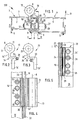
- Fig. 1 is a belt assembly 100 with a fixed Frame 1 shown with an aluminum hollow profile 2, whose inside 3 with the inside 6 one inwardly opening casement 4 is aligned, which also consists of an aluminum hollow profile 5.
- the inside pages 3.6 are flat and to the frame or sash level parallel.
- the fixed frame 1 and the sash 4 leave a shadow groove 7 between them, which leads to the inside the frame 1.4 into a wider gap 8 transforms.
- the aluminum hollow profiles 2 and 5 are for thermal insulation reasons over plastic webs 9 with the not shown, also consisting of aluminum hollow profiles parts of the fixed on the weather side Frame 1 and the casement 4 connected.
- each volume 30 consists of a frame hinge part 10 and a wing hinge part 20, which has a hinge pin 12 about the hinge axis A are pivotally connected.
- the frame hinge part 10 includes a hinge pin 12 receiving Hinge part 13 with a cylindrical, "roller-shaped" outer circumference, which is close to the inside 3.6 of the hollow profiles 2.5 is arranged. Sitting on the hinge part 13 integrally a fastening leg designated as a whole with 14.
- the flat, essentially flat starting part 14 "of the mounting leg 14 extends vertically and perpendicular to the inside 3.6 in the interior of the gap 8 between the aluminum hollow sections 2.5 into it. In this interior is the fastening leg 14 in the manner particularly evident from FIG. 2 twice angled by 90 °. The free perpendicular to the Inside 3 of the frame in the depth of the gap 8 reaching end part 14 'of the fastening leg 14 is too parallel to the initial part 14 ".
- this has in the installation position the frame hinge part 10 arranged wing hinge part 20, which transfers the load of the wing to the frame hinge part 10, a cylindrical, "roll-shaped" hinge part 23 with a mounting leg angled twice by 90 ° 24, which is similar to that Attachment leg 14 and its flat beginning 24 " arranged vertically and perpendicular to the inner sides 3,6 and engages in the gap space and its end part 24 ' against a perpendicular to the front surface 6 of the hollow profile 5 of the casement 4 extends wall 25, which delimits the gap space 8 on the other side.
- the End part 24 ' is also by means of it and the wall 25 penetrating and engaging in a threaded piece 27 Screws 26 attached to the sash 4.
- the aluminum hollow profile 2 of the fixed frame 1 has a substantially rectangular cross section and forms one on the edge adjacent to the shadow groove 7 from the inside 3 recessed paragraph 18, in the the first bend of the fastening leg 14 or nestles 24.
- the gap space 8 is inwards from a projecting region 19 of the inner wall of the Aluminum hollow profile 5 covered with its free Edge up to paragraph 18 of the hollow aluminum profile 2 enough and there carries a groove 21 on the back, in a sealing profile above and below the band 30 22 runs in the form of a lip seal that extends around the frame opening and the wing seals against drafts.
- the sealing profile 22 is interrupted, i.e. it is enough one end 22 '(FIG. 4) from below to the frame hinge part 10 approach and sit with another end 22 "above of the wing hinge part 20 (FIG. 5).
- sealing profile sections 28, 29 In the area of the band 30 take sealing profile sections 28, 29 the function of the sealing profile 22, which in to the hinge axis A parallel C-grooves 32 of the frame hinge part 10 and 33 of the wing hinge part 20 arranged and as Hose seals are formed.
- the sealing profile sections 28, 29 have the length of the frame hinge part 10 or of the wing hinge part 20 so that they are below and above of the band 30 to the ends 22 ', 22 "of the sealing profile 22 and connect in the middle. It follows so an uninterrupted sealing strip also in the area the tapes 30, without the aluminum hollow profiles involved 2.5 or something on the sealing profile 22 would have to be changed or taken away.
- the sealing profile sections 28.29 sit with rear attachment lugs in the grooves 32, 33 of the fastening legs 14, 24 and lie down against the when closing the wing Direction of arrow 11 out of the gap space 8 in opposite directions against the wall 25 or the wall 15, so that the sealing profile sections 28,29 can perform their function normally and get one optimal sealing results.
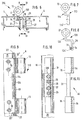
- FIG Fig. 1 to 5 corresponding parts with the same reference numerals characterized. Modified but functional to each other corresponding parts have a reference number increased by 100.
- the belt assembly 200 includes belts 130 that are designed as so-called three-part or hinge straps formed are.
- the frame hinge part 110 has two in the installed position vertical hinge parts 13 in one piece by the fastening leg 114 are interconnected.
- the wing hinge part 120 corresponds essentially the wing hinge part 20 and engages with its hinge part 23 between the hinge parts 13, 13 of the frame hinge part 110.
- the wing hinge part 124 can thus as an "engaging" hinge part, the frame hinge part 114 be referred to as a "surrounding" band part.
- fittings 35,35 In order to allow the sealing profile section 31 to be received, which is not only in the form of the groove 34 on the Extending the height of the wing hinge part 120 are fittings 35,35 provided, the end portion 124 'and correspond in length to the hinge parts 13, 13 and Have grooves 36,36, the groove 34 up and down continue.
- the fittings 35,35 are flat Web 37 connected to a unitary holding piece 40.
- the web 37 extends in the region of the frame hinge part through a groove 38 in the wall 25 facing bottom or outside of the end portion 124 'of Fastening leg 124 is formed.
- the flat web 137 When tightening of the fastening leg 124 on the wall 25 by means of the screws 26, the flat web 137 is under the end portion 124 'clamped. In this way they form Grooves 34 and 36 one over the height of the frame hinge part 10 continuous receptacle for the sealing profile section 31.
- fastening legs 14, 14 '; - 24.24'; 114, 114 '; 124.124' not through a seal arrangement must be led across, but yourself Carrier and / or contact surface for the separate short Sealing profile sections 28, 29 and 31 are.
Landscapes
- Engineering & Computer Science (AREA)
- Civil Engineering (AREA)
- Structural Engineering (AREA)
- Mechanical Engineering (AREA)
- Specific Sealing Or Ventilating Devices For Doors And Windows (AREA)
- Refrigerator Housings (AREA)
- Hinges (AREA)
- Pens And Brushes (AREA)
Description
Claims (5)
- Bandanordnung (100,200) mit mehreren Bändern (30,130) für Türen, Fenster und dergleichen mit einem feststehenden Rahmen und einem Flügel, wobei Rahmen und Fügel mittels der Bänder (30,130) um eine Scharnierachse (A) schwenkbar miteinander verbunden sind, wobei jedes Band (30,130) einen an dem feststehenden Rahmen befestigten und einen am Flügel befestigten Bandteil (10,110,20,120) umfasst, die um einen die Scharnierachse (A) bildenden Bandbolzen (12) schwenkbar aneinander gelagert sind,
wobei mindestens eines der Bandteile mittels eines im wesentlichen senkrecht zur Rahmen- bzw. Flügelebene in den Spaltraum (8) zwischen dem feststehenden Rahmen und dem Flügel eingreifenden Befestigungsschenkel (14,14';24,24';114,114';124,124') an dem feststehenden Rahmen oder dem Flügel befestigt ist und zur Abdichtung des Flügels ein um die Rahmenöffnung sich erstreckendes, an dem feststehenden Rahmen oder dem Flügel befestigtes elastisches Dichtungsprofil (22) vorgesehen ist, welches sich beim Schließen des Flügels dichtend gegen eine Anlagefläche (18) an dem anderen Teil legt und in dem Bereich eines Bandes (30,130) - parallel zur Scharnierachse (A) gesehen - unterbrochen ist,
dadurch gekennzeichnet, daß die Enden (22',22") des Dichtungsprofils (22) von oben und unten an das Band (30,130) heranreichen
und daß jedem Bandteil (10,20;110,120) jeweils ein von dem Dichtungsprofil (22) separater Dichtungsprofilabschnitt (28,29,31) zugeordnet ist, der in dem Spaltraum in Nuten (32,33;34,36) des betreffenden Bandteils (10,20;120) gehalten ist und sich beim Schließen des Flügels gegen eine benachbarte Anlagefläche (15,25;114') legt. - Bandanordnung (100) nach Anspruch 1, dadurch gekennzeichnet, daß das Band (30) ein zweiteiliges Band ist und jedem Bandteil (10,20) ein eigener Dichtprofilabschnitt (28 bzw. 29) zugeordnet ist.
- Bandanordnung (200) nach Anspruch 1, dadurch gekennzeichnet, daß das Band (130) ein dreiteiliges Band ist und ihm ein über die Erstreckung des Bandes (130) parallel zur Scharnierachse (A) durchgehender einzelner Dichtprofilabschnitt (31) zugeordnet ist, der am eingreifenden Bandteil (120) festgelegt ist und sich gegen den Befestigungsschenkel (114) des umschließenden Bandteils (110) legt.
- Bandanordnung nach Anspruch 3, dadurch gekennzeichnet, daß der Befestigungsschenkel (114) des eingreifenden Bandteils (110) eine zur Scharnierachse (A) parallele Nut (34) zur Aufnahme des Dichtprofilabschnittes (31) aufweist und sich an ihm in jeder Richtung je ein den Querschnitt des Befestigungsschenkels (114) fortsetzendes Formstück (35,35) anschließt, das sich jeweils bis an ein Ende des umschließenden Bandteils (110) erstreckt.
- Bandanordnung (200) nach Anspruch 4, dadurch gekennzeichnet, daß die Formstücke (35,35) durch einen flachen Steg (37) zu einem einheitlichen Haltestück (40) verbunden sind, der in einer Nut (38) des Befestigungsschenkels (114) des eingreifenden Bandteils (110) Platz findet und bei der Festlegung des eingreifenden Bandteils (110) mittels dessen Befestigungsschrauben (26) zwischen dem Befestigungsschenkel (114) des eingreifenden Bandteils (110) und dessen Befestigungswand (25) festlegbar ist.
Applications Claiming Priority (2)
| Application Number | Priority Date | Filing Date | Title |
|---|---|---|---|
| DE29900425U | 1999-01-13 | ||
| DE29900425U DE29900425U1 (de) | 1999-01-13 | 1999-01-13 | Bandanordnung für Türen, Fenster u.dgl. |
Publications (2)
| Publication Number | Publication Date |
|---|---|
| EP1022425A1 EP1022425A1 (de) | 2000-07-26 |
| EP1022425B1 true EP1022425B1 (de) | 2004-01-07 |
Family
ID=8067873
Family Applications (1)
| Application Number | Title | Priority Date | Filing Date |
|---|---|---|---|
| EP99125075A Expired - Lifetime EP1022425B1 (de) | 1999-01-13 | 1999-12-16 | Bandanordnung für Türen, Fenster und dergleichen |
Country Status (5)
| Country | Link |
|---|---|
| EP (1) | EP1022425B1 (de) |
| AT (1) | ATE257543T1 (de) |
| DE (2) | DE29900425U1 (de) |
| DK (1) | DK1022425T3 (de) |
| ES (1) | ES2213970T3 (de) |
Cited By (1)
| Publication number | Priority date | Publication date | Assignee | Title |
|---|---|---|---|---|
| EP4296458A1 (de) | 2022-06-22 | 2023-12-27 | "WALA" Spolka. z o.o. | Wärmeisolierte scharnieranordnung |
Families Citing this family (8)
| Publication number | Priority date | Publication date | Assignee | Title |
|---|---|---|---|---|
| DE20006906U1 (de) | 2000-04-14 | 2001-08-23 | Dr. Hahn GmbH & Co. KG, 41189 Mönchengladbach | Bandanordnung für Türen, Fenster u.dgl. |
| DE102004016413A1 (de) * | 2004-03-31 | 2005-10-20 | Fuhr Carl Gmbh & Co Kg | Falzband mit Dichtstreifen |
| AT413731B (de) * | 2004-05-03 | 2006-05-15 | Pfisterer Rudolf | Fenster oder tür |
| DE202005008633U1 (de) * | 2005-05-31 | 2006-10-19 | Dr. Hahn Gmbh & Co. Kg | Bandsystem |
| DE202005018959U1 (de) * | 2005-12-02 | 2007-04-12 | Hahn Gmbh & Co Kg Dr | Anordnung eines schwenkbar in einem Rahmen angeordneten Flügels einer Tür, eines Fensters o.dgl. |
| DE202008014611U1 (de) * | 2008-11-04 | 2010-03-25 | Dr. Hahn Gmbh & Co. Kg | Bandanordnung zur um eine Scharnierachse scharniergelenkigen Verbindung eines Flügels mit einem Rahmen |
| FR3008727B1 (fr) * | 2013-07-22 | 2016-02-05 | Axalys | Paumelle comprenant un joint d'etancheite |
| CN106639819A (zh) * | 2016-10-31 | 2017-05-10 | 中电声韵声学工程技术(北京)有限公司 | 隔音门、隔音门门框 |
Family Cites Families (7)
| Publication number | Priority date | Publication date | Assignee | Title |
|---|---|---|---|---|
| DE7504457U (de) * | 1975-06-19 | Friedrich Richardt Stahlbau Ohg | Unfallschutz- und Abdeckleiste an den Nebenschlfeßkanten von Toren | |
| DE7129211U (de) * | 1971-07-30 | 1971-10-28 | Suhr W Baubeschlagfabrik Kg | Schwingfluegellager |
| DE2336690C3 (de) * | 1973-07-19 | 1980-07-03 | Vereinigte Baubeschlagfabriken Gretsch & Co Gmbh, 7250 Leonberg | Abdichtvorrichtung für Schwing- oder Wendeflügel von Fenstern, Türen o.dgl |
| FR2711719B1 (fr) * | 1993-10-27 | 1996-01-12 | Alcan France | Perfectionnement aux paumelles d'articulation d'un ouvrant sur un dormant. |
| DE29602087U1 (de) * | 1996-02-07 | 1997-06-05 | Dr. Hahn GmbH & Co. KG., 41189 Mönchengladbach | Bandanordnung für Türen, Fenster u.dgl. |
| DE29704546U1 (de) * | 1997-03-13 | 1997-04-30 | KBE Vertriebsgesellschaft für Kunststoffprodukte GmbH, 66763 Dillingen | Winkelbandschere zum dreh- und kippbaren Anschlagen eines Flügelrahmens an einem Blendrahmen von Fenstern oder Türen |
| DE29712633U1 (de) * | 1997-07-17 | 1997-09-18 | Schüco International KG, 33609 Bielefeld | Anschlagdichtung für Fenster, Türen oder Fassaden |
-
1999
- 1999-01-13 DE DE29900425U patent/DE29900425U1/de not_active Expired - Lifetime
- 1999-12-16 ES ES99125075T patent/ES2213970T3/es not_active Expired - Lifetime
- 1999-12-16 EP EP99125075A patent/EP1022425B1/de not_active Expired - Lifetime
- 1999-12-16 DK DK99125075T patent/DK1022425T3/da active
- 1999-12-16 DE DE59908251T patent/DE59908251D1/de not_active Expired - Lifetime
- 1999-12-16 AT AT99125075T patent/ATE257543T1/de not_active IP Right Cessation
Cited By (1)
| Publication number | Priority date | Publication date | Assignee | Title |
|---|---|---|---|---|
| EP4296458A1 (de) | 2022-06-22 | 2023-12-27 | "WALA" Spolka. z o.o. | Wärmeisolierte scharnieranordnung |
Also Published As
| Publication number | Publication date |
|---|---|
| DE59908251D1 (de) | 2004-02-12 |
| ATE257543T1 (de) | 2004-01-15 |
| DE29900425U1 (de) | 2000-05-25 |
| DK1022425T3 (da) | 2004-04-26 |
| ES2213970T3 (es) | 2004-09-01 |
| EP1022425A1 (de) | 2000-07-26 |
Similar Documents
| Publication | Publication Date | Title |
|---|---|---|
| EP3339552B1 (de) | Faltanlage mit stellleiste | |
| EP3259428B1 (de) | Dichtungsvorrichtung für fenster- und türelemente | |
| EP1022425B1 (de) | Bandanordnung für Türen, Fenster und dergleichen | |
| EP0298354B1 (de) | Kunststoffrahmen für Fenster, Türen od. dgl. | |
| EP0789124B1 (de) | Bandanordnung für Türen, Fenster und dergleichen | |
| EP0681081A1 (de) | Abschlusselement für Wandöffnungen in Gebäuden od. dgl. | |
| EP0995001B1 (de) | Anordnung eines beschlagteils an einem rahmen | |
| AT399198B (de) | Falt- oder schwingflügeltür | |
| EP1020606B1 (de) | Rahmenloser Glasflügel als bewegbar gelagerter oder ortsfester Flügel eines Fensters, einer Tür oder einer Fassade oder Glaswand | |
| CH637728A5 (de) | Waermegedaemmtes schwing- oder wendefluegelfenster. | |
| EP3680438B1 (de) | Anordnung aus einem rahmenprofil und einem dichtprofil für einen fenster- oder türrahmen | |
| DE69612538T2 (de) | Flügelrahmen für Doppelflügelfenster | |
| DE9403956U1 (de) | Torblatt | |
| EP1441096A1 (de) | Befestigung eines Beschlagteils | |
| EP1582687A2 (de) | Türschwellensystem | |
| DE3400815C1 (de) | Verriegelungsbeschlag an Fenstern, Türen und dergleichen | |
| DE29811017U1 (de) | Befestigung eines Beschlagteils | |
| DE8908513U1 (de) | Torblatt-Scharnier | |
| DE19912839A1 (de) | Leicht montierbarer Zentralverschluß für Flügel | |
| DE10341828B4 (de) | Hohlprofilrahmen für eine Insektenschutztür | |
| DE102015102582B3 (de) | Vorsatztür oder -fenster, insbesondere Insektenschutztür oder -fenster | |
| DE3511426A1 (de) | Vorrichtung zum verschliessen einer oeffnung | |
| DE8507990U1 (de) | Fenster | |
| DE2330874C3 (de) | Schließband für Drehkipp-Fenster, .Türen o.dgl | |
| DE2049851C3 (de) | Abdichtvorrichtung für ein Fenster oder eine Tür |
Legal Events
| Date | Code | Title | Description |
|---|---|---|---|
| PUAI | Public reference made under article 153(3) epc to a published international application that has entered the european phase |
Free format text: ORIGINAL CODE: 0009012 |
|
| AK | Designated contracting states |
Kind code of ref document: A1 Designated state(s): AT BE CH CY DE DK ES FI FR GB GR IE IT LI LU MC NL PT SE |
|
| AX | Request for extension of the european patent |
Free format text: AL;LT;LV;MK;RO;SI |
|
| 17P | Request for examination filed |
Effective date: 20000821 |
|
| AKX | Designation fees paid |
Free format text: AT BE CH CY DE DK ES FI FR GB GR IE IT LI LU MC NL PT SE |
|
| 17Q | First examination report despatched |
Effective date: 20020320 |
|
| GRAP | Despatch of communication of intention to grant a patent |
Free format text: ORIGINAL CODE: EPIDOSNIGR1 |
|
| GRAS | Grant fee paid |
Free format text: ORIGINAL CODE: EPIDOSNIGR3 |
|
| GRAA | (expected) grant |
Free format text: ORIGINAL CODE: 0009210 |
|
| AK | Designated contracting states |
Kind code of ref document: B1 Designated state(s): AT BE CH CY DE DK ES FI FR GB GR IE IT LI LU MC NL PT SE |
|
| PG25 | Lapsed in a contracting state [announced via postgrant information from national office to epo] |
Ref country code: IE Free format text: LAPSE BECAUSE OF FAILURE TO SUBMIT A TRANSLATION OF THE DESCRIPTION OR TO PAY THE FEE WITHIN THE PRESCRIBED TIME-LIMIT Effective date: 20040107 Ref country code: GB Free format text: LAPSE BECAUSE OF FAILURE TO SUBMIT A TRANSLATION OF THE DESCRIPTION OR TO PAY THE FEE WITHIN THE PRESCRIBED TIME-LIMIT Effective date: 20040107 Ref country code: CY Free format text: LAPSE BECAUSE OF FAILURE TO SUBMIT A TRANSLATION OF THE DESCRIPTION OR TO PAY THE FEE WITHIN THE PRESCRIBED TIME-LIMIT Effective date: 20040107 |
|
| REG | Reference to a national code |
Ref country code: GB Ref legal event code: FG4D Free format text: NOT ENGLISH |
|
| REG | Reference to a national code |
Ref country code: CH Ref legal event code: EP |
|
| REG | Reference to a national code |
Ref country code: IE Ref legal event code: FG4D Free format text: GERMAN |
|
| REF | Corresponds to: |
Ref document number: 59908251 Country of ref document: DE Date of ref document: 20040212 Kind code of ref document: P |
|
| REG | Reference to a national code |
Ref country code: SE Ref legal event code: TRGR |
|
| PG25 | Lapsed in a contracting state [announced via postgrant information from national office to epo] |
Ref country code: GR Free format text: LAPSE BECAUSE OF FAILURE TO SUBMIT A TRANSLATION OF THE DESCRIPTION OR TO PAY THE FEE WITHIN THE PRESCRIBED TIME-LIMIT Effective date: 20040407 |
|
| REG | Reference to a national code |
Ref country code: DK Ref legal event code: T3 |
|
| GBV | Gb: ep patent (uk) treated as always having been void in accordance with gb section 77(7)/1977 [no translation filed] |
Effective date: 20040107 |
|
| REG | Reference to a national code |
Ref country code: CH Ref legal event code: NV Representative=s name: R. A. EGLI & CO. PATENTANWAELTE |
|
| REG | Reference to a national code |
Ref country code: IE Ref legal event code: FD4D |
|
| REG | Reference to a national code |
Ref country code: ES Ref legal event code: FG2A Ref document number: 2213970 Country of ref document: ES Kind code of ref document: T3 |
|
| ET | Fr: translation filed | ||
| PLBE | No opposition filed within time limit |
Free format text: ORIGINAL CODE: 0009261 |
|
| STAA | Information on the status of an ep patent application or granted ep patent |
Free format text: STATUS: NO OPPOSITION FILED WITHIN TIME LIMIT |
|
| PG25 | Lapsed in a contracting state [announced via postgrant information from national office to epo] |
Ref country code: LU Free format text: LAPSE BECAUSE OF NON-PAYMENT OF DUE FEES Effective date: 20041216 |
|
| 26N | No opposition filed |
Effective date: 20041008 |
|
| PG25 | Lapsed in a contracting state [announced via postgrant information from national office to epo] |
Ref country code: MC Free format text: LAPSE BECAUSE OF NON-PAYMENT OF DUE FEES Effective date: 20041231 |
|
| PG25 | Lapsed in a contracting state [announced via postgrant information from national office to epo] |
Ref country code: PT Free format text: LAPSE BECAUSE OF NON-PAYMENT OF DUE FEES Effective date: 20040607 |
|
| PGFP | Annual fee paid to national office [announced via postgrant information from national office to epo] |
Ref country code: NL Payment date: 20081203 Year of fee payment: 10 Ref country code: DK Payment date: 20081212 Year of fee payment: 10 |
|
| PGFP | Annual fee paid to national office [announced via postgrant information from national office to epo] |
Ref country code: FI Payment date: 20081212 Year of fee payment: 10 |
|
| PGFP | Annual fee paid to national office [announced via postgrant information from national office to epo] |
Ref country code: ES Payment date: 20090120 Year of fee payment: 10 |
|
| PGFP | Annual fee paid to national office [announced via postgrant information from national office to epo] |
Ref country code: SE Payment date: 20091207 Year of fee payment: 11 Ref country code: CH Payment date: 20091215 Year of fee payment: 11 Ref country code: AT Payment date: 20091211 Year of fee payment: 11 |
|
| PGFP | Annual fee paid to national office [announced via postgrant information from national office to epo] |
Ref country code: FR Payment date: 20091221 Year of fee payment: 11 |
|
| REG | Reference to a national code |
Ref country code: NL Ref legal event code: V1 Effective date: 20100701 |
|
| REG | Reference to a national code |
Ref country code: DK Ref legal event code: EBP |
|
| PG25 | Lapsed in a contracting state [announced via postgrant information from national office to epo] |
Ref country code: FI Free format text: LAPSE BECAUSE OF NON-PAYMENT OF DUE FEES Effective date: 20091216 |
|
| PG25 | Lapsed in a contracting state [announced via postgrant information from national office to epo] |
Ref country code: NL Free format text: LAPSE BECAUSE OF NON-PAYMENT OF DUE FEES Effective date: 20100701 |
|
| PG25 | Lapsed in a contracting state [announced via postgrant information from national office to epo] |
Ref country code: DK Free format text: LAPSE BECAUSE OF NON-PAYMENT OF DUE FEES Effective date: 20100104 |
|
| PGFP | Annual fee paid to national office [announced via postgrant information from national office to epo] |
Ref country code: IT Payment date: 20101224 Year of fee payment: 12 |
|
| REG | Reference to a national code |
Ref country code: ES Ref legal event code: FD2A Effective date: 20110408 |
|
| PGFP | Annual fee paid to national office [announced via postgrant information from national office to epo] |
Ref country code: DE Payment date: 20101231 Year of fee payment: 12 |
|
| PG25 | Lapsed in a contracting state [announced via postgrant information from national office to epo] |
Ref country code: ES Free format text: LAPSE BECAUSE OF NON-PAYMENT OF DUE FEES Effective date: 20110328 |
|
| PGFP | Annual fee paid to national office [announced via postgrant information from national office to epo] |
Ref country code: BE Payment date: 20110222 Year of fee payment: 12 |
|
| REG | Reference to a national code |
Ref country code: CH Ref legal event code: PL |
|
| PG25 | Lapsed in a contracting state [announced via postgrant information from national office to epo] |
Ref country code: AT Free format text: LAPSE BECAUSE OF NON-PAYMENT OF DUE FEES Effective date: 20101216 |
|
| REG | Reference to a national code |
Ref country code: FR Ref legal event code: ST Effective date: 20110831 |
|
| REG | Reference to a national code |
Ref country code: SE Ref legal event code: EUG |
|
| PG25 | Lapsed in a contracting state [announced via postgrant information from national office to epo] |
Ref country code: SE Free format text: LAPSE BECAUSE OF NON-PAYMENT OF DUE FEES Effective date: 20101217 Ref country code: ES Free format text: LAPSE BECAUSE OF NON-PAYMENT OF DUE FEES Effective date: 20091217 |
|
| PG25 | Lapsed in a contracting state [announced via postgrant information from national office to epo] |
Ref country code: CH Free format text: LAPSE BECAUSE OF NON-PAYMENT OF DUE FEES Effective date: 20101231 Ref country code: LI Free format text: LAPSE BECAUSE OF NON-PAYMENT OF DUE FEES Effective date: 20101231 Ref country code: FR Free format text: LAPSE BECAUSE OF NON-PAYMENT OF DUE FEES Effective date: 20110103 |
|
| BERE | Be: lapsed |
Owner name: *HAHN G.M.B.H. & CO. K.G. Effective date: 20111231 |
|
| PG25 | Lapsed in a contracting state [announced via postgrant information from national office to epo] |
Ref country code: BE Free format text: LAPSE BECAUSE OF NON-PAYMENT OF DUE FEES Effective date: 20111231 |
|
| PG25 | Lapsed in a contracting state [announced via postgrant information from national office to epo] |
Ref country code: IT Free format text: LAPSE BECAUSE OF NON-PAYMENT OF DUE FEES Effective date: 20111216 |
|
| REG | Reference to a national code |
Ref country code: DE Ref legal event code: R119 Ref document number: 59908251 Country of ref document: DE Effective date: 20130702 |
|
| PG25 | Lapsed in a contracting state [announced via postgrant information from national office to epo] |
Ref country code: DE Free format text: LAPSE BECAUSE OF NON-PAYMENT OF DUE FEES Effective date: 20130702 |