EP1020239A2 - Verfahren und Anlage zum Walzen von Metallband - Google Patents
Verfahren und Anlage zum Walzen von Metallband Download PDFInfo
- Publication number
- EP1020239A2 EP1020239A2 EP00100097A EP00100097A EP1020239A2 EP 1020239 A2 EP1020239 A2 EP 1020239A2 EP 00100097 A EP00100097 A EP 00100097A EP 00100097 A EP00100097 A EP 00100097A EP 1020239 A2 EP1020239 A2 EP 1020239A2
- Authority
- EP
- European Patent Office
- Prior art keywords
- strip
- thin slab
- separating device
- slab
- rolling
- Prior art date
- Legal status (The legal status is an assumption and is not a legal conclusion. Google has not performed a legal analysis and makes no representation as to the accuracy of the status listed.)
- Withdrawn
Links
Images




Classifications
-
- B—PERFORMING OPERATIONS; TRANSPORTING
- B21—MECHANICAL METAL-WORKING WITHOUT ESSENTIALLY REMOVING MATERIAL; PUNCHING METAL
- B21B—ROLLING OF METAL
- B21B15/00—Arrangements for performing additional metal-working operations specially combined with or arranged in, or specially adapted for use in connection with, metal-rolling mills
- B21B15/0007—Cutting or shearing the product
-
- B—PERFORMING OPERATIONS; TRANSPORTING
- B21—MECHANICAL METAL-WORKING WITHOUT ESSENTIALLY REMOVING MATERIAL; PUNCHING METAL
- B21B—ROLLING OF METAL
- B21B2263/00—Shape of product
- B21B2263/20—End shape; fish tail; tongue
-
- B—PERFORMING OPERATIONS; TRANSPORTING
- B21—MECHANICAL METAL-WORKING WITHOUT ESSENTIALLY REMOVING MATERIAL; PUNCHING METAL
- B21B—ROLLING OF METAL
- B21B2273/00—Path parameters
- B21B2273/12—End of product
- B21B2273/14—Front end or leading end
-
- B—PERFORMING OPERATIONS; TRANSPORTING
- B21—MECHANICAL METAL-WORKING WITHOUT ESSENTIALLY REMOVING MATERIAL; PUNCHING METAL
- B21B—ROLLING OF METAL
- B21B2273/00—Path parameters
- B21B2273/12—End of product
- B21B2273/16—Tail or rear end
Definitions
- the invention relates to a method and a system for Rolling of metal strip in a rolling mill, with a preliminary strip or a thin slab in successive steps is rolled out into a metal strip.
- the tape is over its entire length is as uniform as possible should have.
- the width is of a variety influenced by factors, for example the initial geometry of the band, the natural spread and the constriction of the Strip due to the strip tension inside the rolling mill and on the way to the reel.
- the belt can run up in the side guide timely and sufficient opening of the side guide be avoided. However, opening another means that the tape end can continue. You look for a compromise between running sideways and running up the belt in the Side guide. Conditions tighten when at the same time the end of the band is fishtail-shaped.
- the z. B. leaps and bounds in the direction "wider" include, arise on both sides in the Band edge area of corner waves, especially at higher ones Roll wear. These corner waves are on the tape head and in Belt middle section, pulled out by the belt pull. On agglomeration However, at the end of the band these waves build up, so that at larger flatness up to 3 times the strip edge and this will damage the tape end.
- middle section and end of the band to compensate are therefore u. a. usually the tapes pre-compressed in front of the rolling mill by means of a compression stand and then rolled. To the greater spread of the beginning of the band and to counteract the end of the band, the beginning of the band and the end of the band is more compressed than the middle section of the band. After rolling, the unwanted strip shapes are then on Start and end of the band using cropping shears away.
- Such upsetting structures are also used in finished streets Direct processing of thin slabs (slab thickness below 100 mm) arranged in front of the finishing lines.
- the compression efficiency is, however, small due to the relatively low thickness of the thin slab. Furthermore, there is a risk especially at the head and at the end of denting.
- the upsetting also forms a so-called Dog bone profile. This leads when going through the Rolling mill often to special forms of strip start and Band end. At the end of the band there are, for example, so-called Fish tail shapes typical. The fish tails at the end of the belt tend to roll with thin asymmetries when rolling thin strips one-sided tearing. As a result, the process reliability of the Rolling mill affected.
- the possible degree of compression is also limited at the beginning of the belt, because the strip must be securely threaded into the rolling mill. If the tape is too tightly compressed at the beginning of the tape, it can happen that it does not get into the nip, but on a roller hits and stops.
- the task is solved with a method for Rolling of metal strip in a rolling mill, with a preliminary strip or a thin slab in successive steps is rolled out into a metal strip by the characteristic Measures of claim 1.
- a corresponding system for Implementation of this method is specified in claim 10.
- the finished strip dimensions are preserved metrologically recorded and to calculate the required Size of the separation areas of the next opening act or the thin slab and to regulate the separating device used. This is a quick adjustment in itself resulting deviations possible, for example by changed temperature or dimensions of the supporting strip or Thin slab and under constant rolling conditions is a optimal approximation to the desired tape dimensions in allows a few control steps.
- the separation has also been calculated and regulated Inclusion of the input thickness of the supporting strip or the Thin slab in this calculation (thickness ratio of Finished strip and preliminary strip or thin slab) have proven to be useful.
- the separation of the predetermined or subsequent calculated areas of the front and / or rear end of the Supporting strip or thin slab with the separator is done accordingly the invention during the transport of the supporting strip or Thin slab in the rolling mill. It is therefore necessary that Transport speed of the support strip or thin slab of Adapt the cutting speed of the cutting device, especially when the separator is only transverse to Transport direction of the sliver or thin slab can be moved is. If the separator is also parallel to Transport direction of the sliver or thin slab can be moved is, the compulsion to adjust the speeds (Transport speed, separation speed) reduced; in addition is then with this separator also a separation of intricately designed areas during transport of the pre-strip or thin slab possible.
- the Cutting device at the right time with the cutting process begin (start of feed of the separating device), which is why good material tracking and continuous Distance measurement between the preliminary slab or thin slab and the separating device is required, the measured values for Scheme can be used.
- a plant for carrying out the method of the invention consists of a rolling mill with the characteristic feature, that in front of the first roll stand one with at least one Feed device provided separation device is present.
- This separation device for example a Cutting device, a milling or sawing device or a Cutting torch (also is a laser cutting torch possible), can be moved with a Formed feed device.
- this feed device can be driven sideways against the support strip or thin slab and, if the transport speed of the supporting strip or Thin slab matches the cutting speed, an area to the side of the support strip or thin slab Cut off the desired shape and size.
- the separating device can also be equipped with another drive through which they also parallel to the direction of transport of the supporting strip or Thin slab is movable.
- the shape and size of the areas to be separated are first predetermined, but are then according to the invention on the basis of finished strip dimensions obtained and the obtained Results used to control the separator.
- a Control device connected in the measurement signals from Flow sensors flow in front of the separator (Measurement of the input geometry and position of the supporting strip or the thin slab) and / or behind the separator (measurement of the finished strip dimensions) are arranged.
- a measuring device for measuring the Distance between the separator and the front and / or the rear end of the preliminary strip or the thin slab arranged, the measured values also in the Flow control device and for precise control of the Contribute drive of the separator.
- the system according to the invention is a processing of front and / or rear ends of the supporting strip or Thin slab in a conventional rolling mill in addition to Use of an edger in the Vorée possible, the Cutting device in the area of the cropping shear in front of the Finishing line is arranged.
- the invention can also be done before Finishing line or preferably in the cropping shear area be placed in the oven, as here low Slab speeds can be realized.
- Figure 1 shows a tongue-shaped band end 2 of a metal band 1, the rear edge 3 against the belt conveying direction 6 after bulging outside the metal band 1 extended by the area 5 and at the same time laterally the metal band 1 around the area 4 widened.
- Figure 2 is a strip end of a metal strip 1 in the form of a fish tail-like band end 7 shown.
- Trailing edge 8 inwards in the direction of the belt conveying direction 6 warping, as a result of which regions tapering to the side 9 have arisen.
- the metal strip 1 is also here widened laterally by areas 4.
- the tongue-shaped band end 2 is again one Metal strip 1 shown.
- this redundant rolling stock 4, 5 before the first Rolling stitch removed from the support or from the thin slab (cut off) it is possible to make a finished tape accordingly to manufacture the target shape 13.
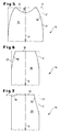
- FIG Target shape 13 of the finished tape now went like a figure 5 shows corresponding areas 4 ′, 5 ′ at the rear end 15 of the band of the preliminary strip or thin slab 14 separated.
- 5 is the rear end 15 one machined in this way Vorbandes or a thin slab 14 and dashed the contour 17 of the preliminary strip or thin slab 14 before processing shown so that the shape and size of the separated areas 4 'and 5' are identified.
- the editing was done in such a way that on both sides of the supporting strip or Thin slab 14 the side dividing line 19 symmetrical to End of slab or thin slab towards and in the middle of the sliver middle area, the rear edge 16 in the belt conveying direction 6 have been moved inwards.
- FIGS. 6 and 7 Further processing options are shown in FIGS. 6 and 7 the front and / or rear ends of the supporting strip or Shown thin slab.
- 6 is the supporting strip or Thin slab end 18 by symmetrical separation laterally Areas have been processed, the dividing line 19 to The end of the tape runs linearly in steps towards the middle of the tape. It triangle-like separation regions 4 'are thus formed.
- the Trailing edge 16 was not in this embodiment processed, therefore it runs parallel and congruent with the contour 17 of the unprocessed forehand or Thin slab end.
- FIG. 7 shown Another embodiment of a processed pre-strip or thin slab end 20 is in FIG. 7 shown.
- the method of the invention are different large and deviating areas from each other Supporting tape or the thin slab is separated to this way Finished tape to get that of the given target shape corresponds.
- the shape and size of the separation areas result thereby from the shape and size of the roll end rollings and / or of the areas which after the rolling of the target shape of the Finished tape deviate. Because first of all the shape and size of this Areas are still unknown, it is appropriate to start with a symmetrically machined pre-strip or thin slab end to start and from the resulting deviations of the Finished tape from the target shape to the other separation areas to calculate.
- a target width shape 13 ' is specified, which creates a narrower finished width at the near end of the belt (see Fig. 4). This can result in the strip end rolling Band course can be effectively combated.
- the corresponding ones are separated Areas of the preliminary strip or thin slab during their Transportes in the plant, d. H. in front of the oven one CSP system, in front of the finishing train or within the Rolling mill. This means that with separators that can only be moved transversely to the belt conveying direction Belt conveyor speed to the cutting speed needs to be adjusted.
- FIG. 8 a CSP system with a separating device arranged in front of the furnace is shown in a diagram in a diagram of how this adaptation can be carried out by way of example.
- the slab conveying speed v is plotted against the conveying time t in the diagram. Beginning at time t 0 , the exit of the thin slab from the mold, the thin slab is first conveyed to the cropping shear at constant speed v 0 , where the cropping cut is made at time t 1 . The cut thin slab is then accelerated to the speed v 1 and conveyed from the time t 1 'to t 2 ' at the increased speed v 1 . This measure creates a sufficient distance between the thin slab end and the subsequent thin slab start.
- the thin slab is braked to speed v 2 , which corresponds to the separation speed, and the separation process begins at time t 2 until time t 3 . Then the thin slab is accelerated again to the usual speed v 3 for the furnace transport.
- the method described here can be easily adapted to different thin slab dimensions and separation speeds by changing the different speeds, braking and acceleration values, without having to change the length of the overall system.
- FIG. 9 this is schematically shown in a top view symmetrical separation of the areas 4 at the end 18 of a Vorbandes or a thin slab 14 with a separator 30 shown.
- the separator 30, which is next to the side the supporting strip or thin slab 14 is arranged a lever arm 34 with a milling head 31 which has a Feed device in the form of a piston-cylinder unit 32 via a pivot point 35 in the direction of the arrow 33 laterally with its milling head 31 against the supporting strip or the Thin slab 14 is performed.
- a second milling head 31 'on the opposite side of the supporting strip or Thin slab 14 is arranged.
- the shape of the Partition line 19 and the starting points 21 and ending points 22 can by a control device (not shown) be specified and controlled using measured values be in front of the separator from the supporting strip or Thin slab or behind the separator from the finished belt are included (the measuring devices are not shown).
- FIG. 10 and 11 is a cut Representation (Fig. 10) and in a plan view (Fig. 11) one Separating device 40 with flame cutting nozzles 42 shown.
- the Flame cutting nozzles 42 are each with a displacement device 43 arranged on a crossbar 41, which the supporting strip or the thin slab 14 spanned.
- the shifting devices 43 are transverse to the crossbar 41 in both directions Belt conveyor direction 6 displaceable, so that by regulated Feed by means of a (not shown) Feed device the cutting line 19 by cutting generated up to the rear edge 16 and the area 4 'separated becomes.
- the separated material is in a under the separator 40 arranged collecting container (not shown) collected.
- the separation device 40 is not only on the crossbar 41 movably arranged, but in addition is the Crossbar 41 parallel to the belt conveyor 6 through a corresponding feed device (not shown) movable.
- the agreement of separation speed and Belt conveyor speed is no longer mandatory necessary because the crossbar is a necessary Can bring about speed compensation.
- a deburring device 45 arranged with 6 transverse to the belt conveying direction Deburring knives 46 (also are wide fixed knives conceivable), with which the flash burr created during flame cutting can be removed.
- the same deburring device is also behind the cutter heads 31, 31 '(Fig. 9) for elimination of the burr conceivable; however, it was not shown in FIG shown.
- a pressure roller 47 is arranged to compensate for the contact pressure by the Deburring knife 46 is in the middle above the supporting strip or the thin slab 14 .
- a regulation of the feed speed of the crossbar 41 and the shifter 43 is involved corresponding measurements of the opening act before or Finished tape also possible after the separating device, known measuring and control devices are used can, which is why a special illustration in FIGS and 11 failed.
- the presentation of Feed lines of the flame cutting nozzles 42 are dispensed with. At conventional flame cutting nozzles would be these gas lines, for laser cutting torches (expensive, but with high Cutting performance) corresponding electrical supply lines.
Landscapes
- Engineering & Computer Science (AREA)
- Mechanical Engineering (AREA)
- Metal Rolling (AREA)
Abstract
Description
- Hochlaufen des Bandes in der Seitenführung und somit zu Bandrissen infolge doppelter Dickenabnahme an der Kante
- z. T. einseitige Zipfelwellen, besonders bei hohem Arbeitswalzenverschleiß und möglicherweise dreifacher örtlicher Dickenreduktion, wenn Wellen aufgestaut und umgefaltet werden
- einseitigen strammen Kanten, die bei dem kleinsten Randfehler einreißen können.
- Fig. 1
- das Ende eines Metallbandes nach der Walzung gemäß dem Stand der Technik in einer Draufsicht,
- Fig. 2
- das Ende eines Metallbandes nach der Walzung gemäß dem Stand der Technik in einer Draufsicht,
- Fig. 3
- das Ende eines Metallbandes nach der Walzung gemäß dem Stand der Technik in einer Draufsicht,
- Fig. 4
- das Ende eines Metallbandes nach der Walzung gemäß dem Stand der Technik in einer Draufsicht,
- Fig. 5
- das Ende eines Vorbandes, bearbeitet nach dem Verfahren der Erfindung in einer Draufsicht,
- Fig. 6 u. 7
- das Ende eines Vorbandes bearbeitet nach dem Verfahren der Erfindung in einer Draufsicht,
- Fig. 8
- ein Diagramm der Vorband- bzw. Dünnbrammengeschwindigkeit,
- Fig. 9
- eine Prinzipskizze einer Abtrennvorrichtung in einer Draufsicht,
- Fig. 10
- eine Abtrennvorrichtung gemäß der Erfindung in einem Vertikalschnitt,
- Fig. 11
- eine Draufsicht auf die Abtrennvorrichtung gemäß Fig. 10.
Claims (13)
- Verfahren zum Walzen von Metallband (1) in einer Walzstraße, wobei ein Vorband bzw. eine Dünnbramme (14) in aufeinander folgenden Arbeitsschritten zu einem Metallband (1) ausgewalzt wird, dadurch gekennzeichnet, dass zur Kompensation von unregelmäßigen Fertigbandabmessungen und/oder Bandpositionen, die durch die Walzung der vorderen und/oder hinteren Vorband- bzw. Dünnbrammenenden (15, 18, 20) entstehen, vor dem Eintritt des Vorband- bzw. Dünnbrammenkopfes und/oder des Vorband- bzw. Dünnbrammenendes (15, 18, 20) in das erste Walzgerüst ein oder mehrere Bereiche (4', 4'', 5'), des Vorband- bzw. Dünnbrammenkopfes und/oder des Vorband- bzw. Dünnbrammenendes (15, 18, 20) mit mindestens einer Trennvorrichtung (30, 40) abgetrennt werden.
- Verfahren nach Anspruch 1, dadurch gekennzeichnet, dass die Abtrennung der Vorband- bzw. Dünnbrammenbereiche (4', 4'', 5') durch einen Schneidvorgang und/oder einen Fräs- oder Sägevorgang und/oder einen Schneidbrennvorgang erfolgt.
- Verfahren nach Anspruch 2, dadurch gekennzeichnet, dass das Abtrennen während des Transportes des Vorbandes bzw. der Dünnbramme (14) zur oder in der Walzstraße erfolgt.
- Verfahren nach Anspruch 3, dadurch gekennzeichnet, dass die Transportgeschwindigkeit (v2) des Vorbandes bzw. der Dünnbramme (14) an die Trenngeschwindigkeit der Trennvorrichtung (30, 40) und der dadurch bedingten Vorschubgeschwindigkeit der Trennvorrichtung angepasst wird.
- Verfahren nach einem oder mehreren der Ansprüche 1 bis 4, dadurch gekennzeichnet, dass zur Berechnung der erforderlichen Größe der Abtrennbereiche (4', 4'', 5') des anstehenden oder des nachfolgenden Vorband- bzw. Dünnbrammenendes (15, 18, 20) und zur Regelung der Vorband- bzw. Dünnbrammengeschwindigkeit (v2) bzw. der Vorschubgeschwindigkeit der Trennvorrichtung Messwerte verwendet werden, die vor der Trennvorrichtung (30, 40) vom Vorband bzw. Dünnbramme (14) und/oder die nach der Trennvorrichtung (30, 40) vom Fertigband stammen.
- Verfahren nach Anspruch 5, dadurch gekennzeichnet, dass zur Regelung Messwerte verwendet werden, die nach dem Walzen noch in der Walzstraße und/oder unmittelbar nach Verlassen der Walzstraße am Fertigband in Form von Fertigbandabmessungen oder Bandmittenabweichungen ermittelt werden.
- Verfahren nach Anspruch 5 oder 6, dadurch gekennzeichnet, dass zur Regelung Messwerte verwendet werden, die hinter der Trennvorrichtung (30, 40) am Vorband bzw. an der Dünnbramme (14) in Form von aufzubringenden Stauch- bzw. Axialkräften eines hinter der Trennvorrichtung (30, 40) angeordneten Stauchers oder in Form des Dickenverhältnisses zwischen der Eingangsdicke des Vorbandes bzw. der Dünnbramme (14) und den Fertigbandabmessungen ermittelt werden.
- Verfahren nach einem oder mehreren der Ansprüche 5 bis 7, dadurch gekennzeichnet, dass bei geregeltem Betrieb der Trennvorrichtung (30, 40) zur genauen Positionierung der Trennvorrichtung (30, 40) eine kontinuierliche Abstandsmessung zwischen dem durch Abtrennen zu behandelnden vorderen und/oder hinterem Vorband- bzw. Brammenende (15, 18, 20) und der Trennvorrichtung (30, 40) erfolgt.
- Verfahren nach einem oder mehreren der Ansprüche 5 bis 8, dadurch gekennzeichnet, dass auf Grund der erhaltenen Messwerte mit Berücksichtigung des Materialflussverhaltens eine herzustellende Vorband- oder Dünnbrammenform derart berechnet wird, dass eine vorgegebene Ziel-Fertigbandendenform (13, 13') erhalten wird.
- Anlage zum Walzen von Metallband (1) mit einer Walzstraße zur Durchführung des Verfahrens nach den vorherigen Ansprüchen, mit mindestens einem Arbeitswalzgerüst und einer dem Walzgerüst bei Bedarf vorgeordneten Stauchvorrichtung, dadurch gekennzeichnet, dass vor dem ersten Walzgerüst mindestens eine mit mindestens einer Vorschubeinrichtung (32, 43) versehene Trennvorrichtung (30, 40), beispielsweise eine Schneidvorrichtung oder eine Fräs- oder Sägevorrichtung (30) oder eine Schneidbrennvorrichtung (40), zur Abtrennung von Bereichen (4', 4'', 5') des vorderen und/oder hinteren Vorband- bzw. Brammenendes (15, 18, 20) angeordnet ist.
- Anlage nach Anspruch 10, dadurch gekennzeichnet, dass die Trennvorrichtung (30, 40) quer zur Transportrichtung/ Bandförderrichtung (6) des Vorbandes bzw. der Dünnbramme (14) verfahrbar ausgebildet ist.
- Anlage nach Anspruch 10, dadurch gekennzeichnet, dass die Trennvorrichtung (40) zusätzlich parallel zur Transportrichtung (6) des Vorbandes bzw. der Dünnbramme (14) verfahrbar ausgebildet ist.
- Anlage nach Anspruch 11 oder 12, dadurch gekennzeichnet, dass die Trennvorrichtung (30, 40) mit einer Mess- und Regeleinrichtung verbunden ist, in die Messwerte des Vorbandes bzw. der Dünnbramme (14) und/oder des Fertigbandes sowie Messwerte einer Abstandsmessung zwischen dem Vorband bzw. der Dünnbramme und der Trennvorrichtung (30, 40) einfließen und mit der die Form und die Größe der abzutrennenden Bereiche (4', 4'', 5') berechnet und die Vorschubgeschwindigkeit der Abtrennvorrichtung (30, 40) und/oder die Vorband- bzw. Dünnbrammengeschwindigkeit (v2) geregelt und gesteuert werden.
Applications Claiming Priority (2)
| Application Number | Priority Date | Filing Date | Title |
|---|---|---|---|
| DE19900779 | 1999-01-12 | ||
| DE1999100779 DE19900779B4 (de) | 1999-01-12 | 1999-01-12 | Verfahren zum Walzen von Metallband und Anlage zur Durchführung des Verfahrens |
Publications (2)
| Publication Number | Publication Date |
|---|---|
| EP1020239A2 true EP1020239A2 (de) | 2000-07-19 |
| EP1020239A3 EP1020239A3 (de) | 2003-01-15 |
Family
ID=7893988
Family Applications (1)
| Application Number | Title | Priority Date | Filing Date |
|---|---|---|---|
| EP00100097A Withdrawn EP1020239A3 (de) | 1999-01-12 | 2000-01-07 | Verfahren und Anlage zum Walzen von Metallband |
Country Status (2)
| Country | Link |
|---|---|
| EP (1) | EP1020239A3 (de) |
| DE (1) | DE19900779B4 (de) |
Cited By (1)
| Publication number | Priority date | Publication date | Assignee | Title |
|---|---|---|---|---|
| US10730088B2 (en) * | 2014-05-30 | 2020-08-04 | Jfe Steel Corporation | Method for manufacturing hot-rolled steel sheet, steel sheet cutting location setting device, steel sheet cutting location setting method, and steel sheet manufacturing method |
Families Citing this family (3)
| Publication number | Priority date | Publication date | Assignee | Title |
|---|---|---|---|---|
| DE10318286B3 (de) * | 2003-04-22 | 2004-10-21 | Thyssenkrupp Stahl Ag | Verfahren zum Herstellen von warmverformten Metallflachprodukten aus Brammen |
| CN103252347A (zh) * | 2012-02-21 | 2013-08-21 | 宝山钢铁股份有限公司 | 减少热轧中间坯头尾切舍量的连铸板坯头尾形状预控方法 |
| EP2905089A1 (de) * | 2014-02-07 | 2015-08-12 | Primetals Technologies Austria GmbH | Vorrichtung und Verfahren zur Entfernung von Brenngraten an Schleißkörpern zur Führung von Metallbändern |
Family Cites Families (7)
| Publication number | Priority date | Publication date | Assignee | Title |
|---|---|---|---|---|
| JPS6038201B2 (ja) * | 1978-09-04 | 1985-08-30 | 石川島播磨重工業株式会社 | 圧延材端部形状制御装置 |
| JPS5581067A (en) * | 1978-11-29 | 1980-06-18 | Sumitomo Metal Ind Ltd | Cutting device of steel material while hot |
| JPS5923884B2 (ja) * | 1980-02-20 | 1984-06-05 | 新日本製鐵株式会社 | 張力制御方法 |
| JPH0428408A (ja) * | 1990-05-22 | 1992-01-31 | Ishikawajima Harima Heavy Ind Co Ltd | 圧延設備 |
| NL9100911A (nl) * | 1991-03-22 | 1992-10-16 | Hoogovens Groep Bv | Inrichting en werkwijze voor het vervaardigen van warmgewalst staal. |
| JPH08309401A (ja) * | 1995-05-16 | 1996-11-26 | Kobe Steel Ltd | スラブ及びスラブ前後端加工方法 |
| DE19757486A1 (de) * | 1997-12-23 | 1999-06-24 | Schloemann Siemag Ag | Walzverfahren für ein Metallband |
-
1999
- 1999-01-12 DE DE1999100779 patent/DE19900779B4/de not_active Expired - Fee Related
-
2000
- 2000-01-07 EP EP00100097A patent/EP1020239A3/de not_active Withdrawn
Cited By (1)
| Publication number | Priority date | Publication date | Assignee | Title |
|---|---|---|---|---|
| US10730088B2 (en) * | 2014-05-30 | 2020-08-04 | Jfe Steel Corporation | Method for manufacturing hot-rolled steel sheet, steel sheet cutting location setting device, steel sheet cutting location setting method, and steel sheet manufacturing method |
Also Published As
| Publication number | Publication date |
|---|---|
| DE19900779B4 (de) | 2010-04-01 |
| EP1020239A3 (de) | 2003-01-15 |
| DE19900779A1 (de) | 2000-07-13 |
Similar Documents
| Publication | Publication Date | Title |
|---|---|---|
| EP2445659B1 (de) | Verfahren und vorrichtung zum bearbeiten einer bramme | |
| EP2910316A1 (de) | Einfache Vorsteuerung einer Keilanstellung eines Vorgerüsts | |
| EP2982453A1 (de) | Einstellen eines gezielten Temperaturprofiles an Bandkopf und Bandfuß vor dem Querteilen eines Metallbands | |
| DE2539216A1 (de) | Abbeiz- und walzstrasse | |
| DE112007000641B4 (de) | Kontinuierliche Kaltwalzanlage | |
| DE69822676T2 (de) | Walzanlage und Walzverfahren | |
| EP3544751B1 (de) | Bandlageregelung mit kraftbegrenzter anstellung von seitenführungen an das metallband und korrektur der walzenanstellung | |
| EP0556462B1 (de) | Verfahren und Anlage zum Besäumen von Bändern, insbesondere warmgewalzten Metallbändern | |
| DE69206178T2 (de) | Verfahren und Vorrichtung zum Verbinden erwärmten Materials in einem Warmwalzwerk. | |
| EP4313437B1 (de) | Verfahren und vorrcihtung zum führen und zentrieren eines metallenen walzguts in einer walzstrasse | |
| DE19900779B4 (de) | Verfahren zum Walzen von Metallband und Anlage zur Durchführung des Verfahrens | |
| DE3126385C2 (de) | Verfahren zum Stranggießen von Stahlbrammen | |
| DE3780417T2 (de) | Verfahren zur verminderung der breite von brammen. | |
| DE3534622C2 (de) | ||
| EP0947265B1 (de) | Verfahren zum Stranggiessen und Fertigwalzen eines Giessstranges innerhalb einer vorgegebenen Fertigbreitentoleranz | |
| DE69700739T2 (de) | Verfahren und Vorrichtung zum Schneiden von Brammen in einer Stranggiessanlage | |
| EP0045400A1 (de) | Anlage zum Giesswalzen von Stahl mit hohen Geschwindigkeiten | |
| EP1827735B1 (de) | Verfahren und vorrichtung zum bandgiessen von metallen | |
| AT526531B1 (de) | Entbartung von Walzgut mittels eines Schwingarms | |
| DE19828575B4 (de) | Verfahren und Vorrichtung zum Streckbiegerichten von Metallband | |
| DE10331023A1 (de) | Vorrichtung und Verfahren zum Separieren von Bandstreifen nach der Längsteilung eines Bandes, insbesondere Metallbandes | |
| DE1527612B2 (de) | Einrichtung zum regeln der dicke und querschnittsform bzw. ebenheit von blechen und baendern in walzwerken | |
| DE602004013251T2 (de) | Walzgerüst und Verfahren zum Herstellen von schraubenförmigen Metallbändern | |
| EP0925850A2 (de) | Walzverfahren für ein Metallband | |
| DE10318286B3 (de) | Verfahren zum Herstellen von warmverformten Metallflachprodukten aus Brammen |
Legal Events
| Date | Code | Title | Description |
|---|---|---|---|
| PUAI | Public reference made under article 153(3) epc to a published international application that has entered the european phase |
Free format text: ORIGINAL CODE: 0009012 |
|
| 17P | Request for examination filed |
Effective date: 20000118 |
|
| AK | Designated contracting states |
Kind code of ref document: A2 Designated state(s): AT BE CH CY DE DK ES FI FR GB GR IE IT LI LU MC NL PT SE |
|
| AX | Request for extension of the european patent |
Free format text: AL;LT;LV;MK;RO;SI |
|
| PUAL | Search report despatched |
Free format text: ORIGINAL CODE: 0009013 |
|
| AK | Designated contracting states |
Kind code of ref document: A3 Designated state(s): AT BE CH CY DE DK ES FI FR GB GR IE IT LI LU MC NL PT SE |
|
| AX | Request for extension of the european patent |
Free format text: AL;LT;LV;MK;RO;SI |
|
| AKX | Designation fees paid | ||
| REG | Reference to a national code |
Ref country code: DE Ref legal event code: 8566 |
|
| STAA | Information on the status of an ep patent application or granted ep patent |
Free format text: STATUS: THE APPLICATION IS DEEMED TO BE WITHDRAWN |
|
| 18D | Application deemed to be withdrawn |
Effective date: 20030716 |