EP1019315B1 - Produktivitätspaket - Google Patents
Produktivitätspaket Download PDFInfo
- Publication number
- EP1019315B1 EP1019315B1 EP98950830A EP98950830A EP1019315B1 EP 1019315 B1 EP1019315 B1 EP 1019315B1 EP 98950830 A EP98950830 A EP 98950830A EP 98950830 A EP98950830 A EP 98950830A EP 1019315 B1 EP1019315 B1 EP 1019315B1
- Authority
- EP
- European Patent Office
- Prior art keywords
- forks
- sensor
- load
- fork
- controller
- Prior art date
- Legal status (The legal status is an assumption and is not a legal conclusion. Google has not performed a legal analysis and makes no representation as to the accuracy of the status listed.)
- Expired - Lifetime
Links
Images

Classifications
-
- B—PERFORMING OPERATIONS; TRANSPORTING
- B66—HOISTING; LIFTING; HAULING
- B66F—HOISTING, LIFTING, HAULING OR PUSHING, NOT OTHERWISE PROVIDED FOR, e.g. DEVICES WHICH APPLY A LIFTING OR PUSHING FORCE DIRECTLY TO THE SURFACE OF A LOAD
- B66F9/00—Devices for lifting or lowering bulky or heavy goods for loading or unloading purposes
- B66F9/06—Devices for lifting or lowering bulky or heavy goods for loading or unloading purposes movable, with their loads, on wheels or the like, e.g. fork-lift trucks
- B66F9/075—Constructional features or details
- B66F9/20—Means for actuating or controlling masts, platforms, or forks
- B66F9/22—Hydraulic devices or systems
-
- B—PERFORMING OPERATIONS; TRANSPORTING
- B66—HOISTING; LIFTING; HAULING
- B66F—HOISTING, LIFTING, HAULING OR PUSHING, NOT OTHERWISE PROVIDED FOR, e.g. DEVICES WHICH APPLY A LIFTING OR PUSHING FORCE DIRECTLY TO THE SURFACE OF A LOAD
- B66F9/00—Devices for lifting or lowering bulky or heavy goods for loading or unloading purposes
- B66F9/06—Devices for lifting or lowering bulky or heavy goods for loading or unloading purposes movable, with their loads, on wheels or the like, e.g. fork-lift trucks
- B66F9/075—Constructional features or details
- B66F9/0755—Position control; Position detectors
-
- B—PERFORMING OPERATIONS; TRANSPORTING
- B66—HOISTING; LIFTING; HAULING
- B66F—HOISTING, LIFTING, HAULING OR PUSHING, NOT OTHERWISE PROVIDED FOR, e.g. DEVICES WHICH APPLY A LIFTING OR PUSHING FORCE DIRECTLY TO THE SURFACE OF A LOAD
- B66F9/00—Devices for lifting or lowering bulky or heavy goods for loading or unloading purposes
- B66F9/06—Devices for lifting or lowering bulky or heavy goods for loading or unloading purposes movable, with their loads, on wheels or the like, e.g. fork-lift trucks
- B66F9/075—Constructional features or details
- B66F9/12—Platforms; Forks; Other load supporting or gripping members
- B66F9/16—Platforms; Forks; Other load supporting or gripping members inclinable relative to mast
-
- B—PERFORMING OPERATIONS; TRANSPORTING
- B66—HOISTING; LIFTING; HAULING
- B66F—HOISTING, LIFTING, HAULING OR PUSHING, NOT OTHERWISE PROVIDED FOR, e.g. DEVICES WHICH APPLY A LIFTING OR PUSHING FORCE DIRECTLY TO THE SURFACE OF A LOAD
- B66F9/00—Devices for lifting or lowering bulky or heavy goods for loading or unloading purposes
- B66F9/06—Devices for lifting or lowering bulky or heavy goods for loading or unloading purposes movable, with their loads, on wheels or the like, e.g. fork-lift trucks
- B66F9/075—Constructional features or details
- B66F9/20—Means for actuating or controlling masts, platforms, or forks
- B66F9/24—Electrical devices or systems
-
- G—PHYSICS
- G01—MEASURING; TESTING
- G01G—WEIGHING
- G01G19/00—Weighing apparatus or methods adapted for special purposes not provided for in the preceding groups
- G01G19/08—Weighing apparatus or methods adapted for special purposes not provided for in the preceding groups for incorporation in vehicles
- G01G19/083—Weighing apparatus or methods adapted for special purposes not provided for in the preceding groups for incorporation in vehicles lift truck scale
Definitions
- This invention relates to a method and apparatus for increasing the speed at which a fork lift truck travels and/or the lowering speed of the truck's forks when the forks are unloaded or substantially unloaded.
- the forks are raised and lowered by at least one hydraulic cylinder. It is known to provide a mechanical proportional valve to control the flow of hydraulic fluid to and from that cylinder. Operation of the valve is controlled by an operator via a control handle.
- the hydraulic system including the valve is designed so as to allow the forks, when fully loaded, to descend at a limited rate. No provision is provided to allow the forks to be lowered at an increased rate when the forks are unloaded.
- EP 0343839 to The Raymond Corporation discloses a lift truck control system wherein truck speed which an operator can command is limited by factors including load weight (determined on lift cylinder pressure), load elevation, heading angle and direction of truck travel (forward or reverse). These factors and possibly other optional factors are continually processed by an on-board computer to provide an instantaneous speed signal.
- the maximum speed of a fork lift truck is increased whenever the forks are unloaded or substantially unloaded. Also, the fork lowering speed is increased when the forks are unloaded or substantially unloaded. By increasing the speed of the truck and/or the lowering speed of the forks when the forks are unloaded or substantially unloaded, productivity is increased.
- the pressure of hydraulic fluid within a fork tilt cylinder is monitored either by a pressure switch or a pressure transducer.
- the pressure in the tilt cylinder is a function of the weight being carried by the forks. Whenever that weight is below a predetermined value, then the forks are considered to be unloaded or substantially unloaded and a truck controller will permit a higher truck speed.
- a tilt position sensor is also provided to detect when the forks are tilted to extremes of a fork tilt range. Because the piston in the tilt cylinder tops out or bottoms out when the forks are fully tilted up or down, the pressure detected by the pressure switch or the pressure transducer is not indicative of the actual weight on the forks when the forks are in one of these extreme positions.
- the tilt position sensor may comprise a switch which is activated when the forks are tilted fully up or down.
- the pressure switch is activated or the transducer generates an appropriate signal to the controller whenever the load is above the predetermined value.
- Activation of the tilt position sensor switch indicating that the weight of the load cannot be accurately determined or activation of the pressure switch or generation of an appropriate signal by the transducer indicating that the load is above the predetermined value will result in the speed of the truck being limited to no more than a first maximum speed, i.e., the maximum speed allowable for a fully loaded truck.
- the speed of the truck may be increased up to a second maximum speed which is greater than the first maximum speed. Industry braking standards are still met at the second maximum speed.
- the lowering speed of the forks is controlled by an electrical proportional hydraulic valve which, in turn, is controlled by the truck controller.
- the controller When the weight of the load is below the predetermined value, and the forks are not fully tilted up or down, then the controller generates appropriate signals to the electrical valve so as to allow the forks to descend at an increased rate.
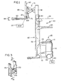
- Fig. 1 illustrates a typical rider reach fork lift truck 100, such as Series RR or RD lift trucks manufactured by Crown Equipment Corporation, the assignee of the present application.
- the truck 100 includes a body 110 which houses a battery 115 for supplying power to a traction motor (not shown) connected to a steerable wheel 120 and to one or more hydraulic motors (not shown) which supply power to several different systems, such as mast, fork and reach hydraulic cylinders.
- the traction motor and the steerable wheel 120 define a drive mechanism for effecting movement of the truck 100.
- An operator's compartment 125 in the body 110 is provided with a steering tiller (not shown) for controlling the direction of travel of the truck 100, and a control handle 135 for controlling travel speed and direction as well as fork height, extension, side shift, and tilt.
- the speed of the truck 100 is measured by a tachometer, represented at 140, included within the truck 100 in a conventional manner.
- An overhead guard 145 is placed over the operator's compartment 125.
- a pair of forks 150 are mounted on a fork carriage mechanism 155 which is in turn mounted on a carriage plate 170.
- the fork carriage mechanism 155 includes a fork carriage 157 and a load back rest 160.
- the forks 150 are coupled to the fork carriage 157 which is in turn coupled to the carriage plate 170.
- the carriage plate 170 is attached to an extensible mast assembly 180 by a scissors reach mechanism 175 extending between the carriage plate 170 and a reach support.
- the reach support is mounted to the mast assembly 180 which includes a fixed, lower mast member 182 and nested movable mast members 184 and 186.
- the reach support is not illustrated in Fig.
- the fork carriage mechanism 155, the carriage plate 170, the mast assembly 180, the reach support and the reach mechanism 175 define a fork carrying assembly.
- the mast assembly 180 includes a plurality of hydraulic cylinders (not shown) for effecting vertical movement of the mast members 184 and 186 and the reach support.
- An electrical proportional hydraulic valve 300 coupled to a truck controller 80, see Fig. 5, controls and directs hydraulic fluid to the mast assembly hydraulic cylinders.
- An operator controls the height of the forks 150 via the control handle 135, which is also coupled to the controller 80.
- the controller 80 In response to receiving fork elevation command signals from the handle 135, the controller 80 generates control signals of an appropriate pulse width to the valve 300 and further generates control signals so as to operate one or more hydraulic fluid pumps (not shown) at an appropriate speed to raise the forks 150.
- the controller 80 In response to receiving fork lowering command signals from the handle 135, the controller 80 generates control signals of an appropriate pulse width to the valve 300 so as to lower the forks 150. As shown in Fig. 1, the movable mast members 184 and 186, as well as the reach support (not illustrated), are raised and the reach mechanism 175 is extended.
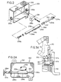
- the forks 150 may be tilted through a range shown by the arrow 195 by means of a hydraulic tilt cylinder 200 coupled to a first portion 157a of the fork carriage 157 and the carriage plate 170, see Fig. 3A.
- the pressure of hydraulic fluid within the tilt cylinder 200 is monitored using a pressure switch or pressure transducer which serves as a pressure sensor 210 that is coupled to the tilt cylinder 200, see Figs. 3, 3A and 4.
- a tilt position sensor 250 see Figs. 2, 2A, 3A and 5, is activated whenever the forks 150 are fully tilted up or down, as will be explained.
- Fig. 4 is a hydraulic schematic diagram for the reach, side shift and tilt functions of the fork lift truck 100 shown in Fig. 1, hydraulic fluid under pressure is supplied to a hydraulic manifold 220 by hydraulic input lines 222 and 224.
- the hydraulic manifold 220 is coupled to the reach support.
- Within the manifold 220 are a pair of check valves POCV and a solenoid valve SVR which controls hydraulic fluid to a pair of reach cylinders 226 and 228, which form part of the scissors reach mechanism 175.
- Hydraulic fluid under pressure is also applied to a manifold 230 which includes a solenoid valve SVT for controlling the operation of the tilt cylinder 200.
- the manifold 230 is coupled to the carriage plate 170.
- a check valve 242 is included in a return line 244, which is in turn connected to the input line 222.
- the pressure sensor 210 is connected to one side of the tilt cylinder 200 to monitor the pressure of the hydraulic fluid in the tilt cylinder 200.
- the pressure in the cylinder 200 is a function of the weight being carried by the forks 150, provided, of course, that the piston in the tilt cylinder 200 has not topped out or bottomed out within the cylinder. When the piston is in one of these two extreme positions, which occurs when the forks 150 are either fully tilted up or down, the pressure detected by the pressure sensor 210 does not correspond to the actual weight of the load on the forks 150.
- the tilt sensor 250 comprises a housing 252 mounted to the carriage plate 170, see Fig. 3A. It has a threaded first opening 252a and a second opening 252b.
- a rod 254 is provided in the housing 252. It includes a first threaded end 254a which threadedly engages the first opening 252a such that the rod 254 is locked in position within the housing 252.
- a plunger 256 having an internal bore (not shown), is received over a nose portion 254b of the rod 254 such that the plunger 256 is permitted to reciprocate back and forth along the rod 254.
- a spring 257 is also received over the nose portion 254b of the rod 254 and biases the plunger 256 in a direction away from the rod first threaded end 254a.
- the plunger 256 has an elongated front portion 256a, first and second camming surfaces 256b and 256c, and an enlarged intermediate portion 256d located between the camming surfaces 256b and 256c.
- An end portion 256e of the plunger engages a second portion 157b of the fork carriage 157, see Figs. 2A and 3A.
- the plunger 256 is caused to move back and forth along the rod 254.
- the button 258a moves downwardly along the camming surface 256c causing the switch 258 to be activated, i.e., to open.
- the button 258a moves downwardly along the camming surface 256b also causing the switch 258 to be activated.
- the tilt sensor switch 258 is activated when the pressure signal generated by the pressure sensor 210 may not correspond to the actual weight on the forks 150 due to the forks 150 being fully tilted up or down.
- the switch 258 is inactivated, i.e., closed, when the forks 150 are not fully tilted up or down such that the button 258a engages the enlarged portion 256d of the plunger 256.
- the pressure sensor 210 may comprise a normally closed pressure switch which is activated, i.e., opened, when the weight on the forks 150 is above a predetermined value or amount, e.g., 1000 pounds at a 24 inch load center.
- the predetermined value may be less than or greater than 1000 pounds.
- the pressure sensor 210 comprises a transducer which provides an output signal proportional to weight.
- the pressure sensor 210 is connected in series with the switch 258 in an input path to the controller 80.
- the switch 258 When the switch 258 is closed, the signal generated by the pressure sensor 210 will pass through the switch 258 and be received by the controller 80.
- the switch 258 When the switch 258 is open, the signal generated by the pressure sensor 210 will not pass through the switch 258 and, hence, will not be received by the controller 80.
- the pressure sensor 210 comprises a normally closed pressure switch and is activated, i.e., the switch is open, and the switch 258 is closed, the input path to the controller 80 is opened.
- the pressure sensor 210 comprises a normally closed pressure switch and is inactivated, i.e., the switch is closed, and the switch 258 is closed, the input path to the controller 80 is closed.
- the electrical block diagram of Fig. 5 shows a speed sensor illustrated as the tachometer 140, the pressure sensor 210, the valve 300, and the tilt sensor 250 connected to a controller 80 taking the form of a microprocessor in the illustrated embodiment.
- the pressure sensor 210 when it comprises a normally closed pressure switch, opens when the weight on the forks 150 is above a predetermined amount. In the illustrated embodiment, if the weight on the forks 150 is above 1000 pounds at a 24 inch load center, the switch opens. Whenever the pressure switch or the tilt sensor switch is open, indicating that the weight on the forks 150 is above the predetermined amount and/or the forks 150 are fully up or down, the controller 80 will only allow the truck to accelerate up to a first maximum speed.
- the controller 80 will allow the truck to accelerate up to a second maximum speed which is greater than the first maximum speed.
- the first maximum first speed is 7.2 MPH when the body 110 is traveling first (5.7 MPH when the forks 150 are traveling first) and the second maximum speed is 7.8 MPH when the body 110 is traveling first (6.5 MPH when the forks 150 are traveling first).
- the first maximum first speed is 7.5 MPH when the body 110 is traveling first (6.2 MPH when the forks 150 are traveling first) and the second maximum speed is 8.3 MPH when the body 110 is traveling first (6.7 MPH when the forks 150 are traveling first).
- the controller 80 when the pressure sensor 210 comprises a pressure switch, the controller 80 requires that the pressure switch maintain a new state (open/closed) for a predetermined time, e.g., 700 milliseconds, before the new state will be recognized.
- the controller 80 will only allow the truck 100 to accelerate up to the second maximum speed when the pressure transducer generates a signal indicating that the weight on the forks 150 is below the predetermined value and the tilt sensor switch is closed. If the pressure transducer generates a signal indicating that the weight on the forks 150 is above the predetermined value and/or the tilt sensor switch is open, then the controller 80 will only allow the truck 100 to accelerate up to the first maximum speed.
- the controller 80 causes the valve 300 to effect downward movement of the forks toward the body 110 or ground (the surface upon which the truck 100 is operated) up to a first maximum speed when the pressure sensor 210 generates a signal to the controller 80 indicative of a load on the forks 150 having a weight above the predetermined value and/or the tilt position sensor switch is open indicating that the forks 150 are in their tilted fully up or down positions.
- the pressure sensor 210 comprises a normally closed pressure switch, it generates a signal to the controller 80 indicative of a load on the forks 150 having a weight above the predetermined value by opening the input path to the controller 80.
- the controller 80 also causes the valve 300 to effect downward movement of the forks 150 toward the body 110 or ground up to a second maximum speed which is greater than the first maximum speed when the pressure sensor 210 generates a signal to the controller 80 indicative of no load or a load on the forks having a weight below the predetermined value and the tilt position sensor switch is closed.
- the pressure sensor 210 comprises a normally closed pressure switch, it generates a signal to the controller 80 indicative of no load or a load on the forks 150 having a weight below the predetermined value by closing the input path to the controller 80.
- the first maximum descent speed may be 90 feet/minute while the second maximum descent speed may be 110 feet/minute.
- the hydraulic system including the valve 300 In order for the forks 150 to descend at a speed up to 110 feet/minute, the hydraulic system including the valve 300 must be designed such that restrictions within that system are minimized.
- the controller 80 may allow the drive mechanism to accelerate the body 110 up to the second maximum speed without increasing the rate at which the forks move toward ground when the pressure sensor 210 generates a signal to the controller 80 indicative of no load or a load on the forks having a weight below the predetermined value and the tilt position sensor switch is closed.
- the controller 80 may increase the rate at which the forks 150 move toward ground without allowing the drive mechanism to accelerate the body 110 up to the second maximum speed when the pressure sensor 210 generates a signal to the controller 80 indicative of no load or a load on the forks having a weight below the predetermined value and the tilt position sensor switch is closed.
- controller may allow the drive mechanism to accelerate the body 110 up to the second maximum speed based only upon signals received from a pressure sensor. It is further contemplated that other conventional sensors not discussed herein may be used for generating signals indicative of the weight of a load on the forks.
Landscapes
- Engineering & Computer Science (AREA)
- Transportation (AREA)
- Structural Engineering (AREA)
- Life Sciences & Earth Sciences (AREA)
- Civil Engineering (AREA)
- Geology (AREA)
- Mechanical Engineering (AREA)
- Combustion & Propulsion (AREA)
- Chemical & Material Sciences (AREA)
- Physics & Mathematics (AREA)
- General Physics & Mathematics (AREA)
- Forklifts And Lifting Vehicles (AREA)
- Control And Other Processes For Unpacking Of Materials (AREA)
- Piezo-Electric Or Mechanical Vibrators, Or Delay Or Filter Circuits (AREA)
- Liquid Crystal Substances (AREA)
Claims (18)
- Gabelstapler, umfassend:eine Karosserie (110);einen Antriebsmechanismus (120), der auf der Karosserie abgestützt ist, um die Bewegung der Karosserie zu bewirken;ein Paar von Gabeln (150);eine Gabel-Trägeranordnung (155, 170, 175, 180), die mit der Karosserie und den Gabeln verbunden ist, um die Gabeln in der Höhe zwischen einer abgesenkten Position und einer gewünschten angehobenen Position zu bewegen, wobei die Gabel-Trägeranordnung einen Kippzylinder (200) zum Kippen der Gabeln über einen Gabel-Kippbereich einschließt;einen ersten Sensor (201), der in der Lage ist, Signale zu erzeugen, die das Gewicht einer Last auf den Gabeln anzeigen, wobei der Sensor dem Kippzylinder zur Überwachung des Fluiddruckes in dem Kippzylinder zugeordnet ist, welcher Druck eine Funktion des Gewichtes ist, das durch die Gabeln getragen wird; undeine Steuerung (80), wobei die Steuerung den Antriebsmechanismus veranlaßt, eine Bewegung der Karosserie bis zu einer ersten maximalen Geschwindigkeit zu bewirken, wenn die Steuerung ein durch den Sensor erzeugtes Signal empfängt, das eine Last auf der Gabel über einem vorbestimmten Gewichtswert anzeigt und den Antriebsmechanismus veranlaßt, eine Bewegung der Karosserie bis zu einer zweiten maximalen Geschwindigkeit zu bewirken, die größer als die erste maximale Geschwindigkeit ist, wenn die Steuerung ein durch den Sensor erzeugtes Signal empfängt, das keine Last oder eine Last auf der Gabel unterhalb des vorbestimmten Gewichtes anzeigt.
- Gabelstapler nach Anspruch 1, wobei der Sensor einen Druckwandler umfaßt.
- Gabelstapler nach Anspruch 1, wobei der Sensor einen Druckschalter umfaßt.
- Gabelstapler nach Anspruch 3, wobei der Druckschalter aktiviert ist, wenn die Gabeln eine Last größer als ungefähr 1000 Pfund tragen.
- Gabelstapler nach Anspruch 1, wobei die Gabel-Trägeranordnung eine Mastanordnung (180) umfaßt, die zwei oder mehr Mastelemente und eine Hebeeinrichtung besitzt, die mit der Karosserie und wenigstens mit einem der Mastelemente gekoppelt ist, wobei die Hebeeinrichtung das wenigstens eine Mastelement veranlaßt, sich gegen und weg von dem Boden zu bewegen und wobei das wenigstens eine Mastelement mit den Gabeln verbunden ist, so daß sich die Gabeln mit dem wenigstens einen Mastelement bewegen.
- Gabelstapler nach Anspruch 5, wobei die Steuerung ferner an die Hebeeinrichtung angeschlossen ist, die Steuerung die Hebeeinrichtung veranlaßt, die Bewegung der Gabeln gegen den Boden bis zu einer ersten maximalen Geschwindigkeit zu bewirken, wenn die Steuerung ein Signal von dem Sensor empfängt, das eine Last auf den Gabeln oberhalb eines vorbestimmten Wertes anzeigt, und die Hebeeinrichtung veranlaßt, die Bewegung der Gabeln gegen den Boden bis zu einer zweiten maximalen Geschwindigkeit zu bewirken, die größer als die erste maximale Geschwindigkeit ist, wenn die Steuerung ein Signal von dem Sensor empfängt, das keine Last oder eine Last auf den Gabeln mit einem Gewicht unterhalb des vorbestimmten Gewichtes anzeigt.
- Gabelstapler nach Anspruch 1, wobei die Steuerung ferner den Antriebsmechanismus veranlaßt, eine Bewegung der Karosserie bis zu der ersten maximalen Geschwindigkeit zu bewirken, wenn kein Signal von dem ersten Sensor durch die Steuerung empfangen wird.
- Gabelstapler nach Anspruch 7, ferner umfassend einen zweiten Sensor (250), der durch den ersten Sensor erzeugte Signale daran hindert, zu der Steuerung zu verlaufen, wenn das Gewicht der Last auf den Gabeln nicht genau bestimmt werden kann.
- Gabelstapler nach Anspruch 8, wobei der zweite Schalter einen Gabel-Kippositions-Sensor umfaßt, welcher in der Lage ist, festzustellen, wann die Gabeln bis zu Extremwerten eines Gabel-Kippbereiches gekippt sind.
- Gabelstapler, umfassend:eine Karosserie (110);einen Antriebsmechanismus (120), der auf der Karosserie abgestützt ist, um die Bewegung der Karosserie zu bewirken;ein Paar von Gabeln (150);eine Gabel-Trägeranordnug (155, 170, 175, 180), die mit der Karosserie und den Gabeln verbunden ist, um die Gabeln in der Höhe zwischen einer abgesenkten Position und einer gewünschten angehobenen Position zu bewegen, wobei die Gabel-Trägeranordnung einen Kippzylinder (200) zum Kippen der Gabeln über einen Gabel-Kippbereich einschließt;einen ersten Sensor (201), der in der Lage ist, Signale zu erzeugen, die das Gewicht einer Last auf den Gabeln anzeigen;einen Gabel-Kippositions-Sensor (250), der in der Lage ist, aktiviert zu werden, wenn die Gabeln zu Extremwerten des Gabel-Kippbereiches gekippt sind; undeine an den Antriebsmechanismus, den ersten Sensor und den Gabel-Kippositions-Sensor angeschlossene Steuerung (80), wobei die Steuerung den Antriebsmechanismus veranlaßt, eine Bewegung der Karosserie bis zu einer ersten maximalen Geschwindigkeit zu bewirken, wenn der wenigstens eine Sensor ein Signal erzeugt, das eine Last auf den Gabeln mit einem Gewicht oberhalb eines vorbestimmten Wertes anzeigt und wenn der Kippositions-Sensor aktiviert ist, und den Antriebsmechanismus veranlaßt, eine Bewegung der Karosserie bis zu einer zweiten maximalen Geschwindigkeit zu bewirken, die größer als die erste maximale Geschwindigkeit ist, wenn der erste Sensor ein Signal erzeugt, das keine Last oder eine Last auf den Gabeln mit einem Gewicht unterhalb des vorbestimmten Wertes anzeigt und der Kippositions-Sensor nicht aktiviert ist.
- Gabelstapler nach Anspruch 10, wobei der erste Sensor dem Zylinder zugeordnet ist, um den Fluiddruck in dem Kippzylinder zu überwachen, welcher Fluiddruck eine Funktion des durch die Gabeln getragenen Gewichtes ist.
- Gabelstapler nach Anspruch 11, wobei der erste Sensor einen Druckwandler umfaßt.
- Gabelstapler nach Anspruch 11, wobei der erste Sensor einen Druckschalter umfaßt.
- Gabelstapler nach Anspruch 13, wobei der Druckschalter aktiviert wird, wenn die Gabeln eine Last größer als ungefähr 1000 Pfund tragen.
- Gabelstapler nach Anspruch 10, wobei die Gabel-Trägeranordnung ferner zwei oder mehr Mastelemente und eine Hebeeinrichtung besitzt, die mit der Karosserie und wenigstens einem der Mastelemente gekoppelt ist, wobei die Hebeeinrichtung das wenigstens eine Mastelement veranlaßt, sich gegen und weg von dem Boden zu bewegen und wobei das eine Mastelement mit den Gabeln verbunden ist, so daß sich die Gabeln mit dem wenigstens einen Mastelement bewegen.
- Gabelstapler nach Anspruch 15, wobei die Steuerung ferner an die Hebeeinrichtung angeschlossen ist, die Steuerung die Hebeeinrichtung veranlaßt, die Bewegung der Gabeln gegen den Boden bis zu einer ersten maximalen Rate zu bewirken, wenn wenigstens der erste Sensor ein Signal erzeugt, das eine Last auf den Gabeln mit einem Gewicht oberhalb eines vorbestimmten Wertes anzeigt und der Kippositions-Sensor aktiviert ist, und die Hebeeinrichtung veranlaßt, die Bewegung der Gabeln gegen den Boden bis zu einer zweiten maximalen Rate zu bewirken, die größer als die erste maximale Rate ist, wenn der erste Sensor ein Signal erzeugt, das keine Last oder eine Last auf den Gabeln mit einem Gewicht unterhalb des vorbestimmten Wertes anzeigt und der Kippositions-Sensor nicht aktiviert ist.
- Gabelstapler nach Anspruch 10, wobei der Kippositions-Sensor einen Schalter (258) umfaßt.
- Gabelstapler, umfassend:eine Karosserie (110);einen Antriebsmechanismus (120), der auf der Karosserie abgestützt ist, um die Bewegung der Karosserie zu bewirken;ein Paar von Gabeln (150);eine Gabel-Trägeranordnung (155, 170, 175, 180), die mit der Karosserie und den Gabeln verbunden ist, um die Gabeln in der Höhe zwischen einer abgesenkten Position und einer gewünschten angehobenen Position zu bewegen, wobei die Gabel-Trägeranordnung eine Mastanordnung mit zwei oder mehr Mastelementen und eine Hebeeinrichtung umfaßt, die mit der Karosserie und wenigstens einem der Mastelemente verbunden ist, wobei die Hebeeinrichtung das wenigstens eine Mastelement veranlaßt, sich gegen den Boden und weg von diesem zu bewegen und das wenigstens eine Mastelement mit den Gabeln verbunden ist, so daß sich die Gabeln mit dem wenigstens einen Mastelement bewegen;einen ersten Sensor (201), der in der Lage ist, Signale zu erzeugen, die das Gewicht einer Last auf den Gabeln anzeigen; undeine an den ersten Sensor und die Hebeeinrichtung angeschlossene Steuerung (80), die die Hebeeinrichtung veranlaßt, eine Bewegung der Gabeln gegen den Boden bis zu einer ersten maximalen Geschwindigkeit zu bewirken, wenn die Steuerung ein Signal vom Sensor empfängt, das eine Last auf den Gabeln oberhalb eines vorbestimmten Wertes anzeigt und die die Hebeeinrichtung veranlaßt; eine Bewegung der Gabeln gegen den Boden bis zu einer zweiten maximalen Geschwindigkeit zu bewirken, die größer als die erste maximale Geschwindigkeit ist, wenn die Steuerung ein Signal von dem Sensor empfängt, das keine Last oder eine Last auf den Gabeln mit einem Gewicht unterhalb des vorbestimmten Wertes anzeigt.
Applications Claiming Priority (3)
| Application Number | Priority Date | Filing Date | Title |
|---|---|---|---|
| US7096997P | 1997-09-30 | 1997-09-30 | |
| US70969P | 1997-09-30 | ||
| PCT/US1998/020624 WO1999016698A1 (en) | 1997-09-30 | 1998-09-29 | Productivity package |
Publications (3)
| Publication Number | Publication Date |
|---|---|
| EP1019315A1 EP1019315A1 (de) | 2000-07-19 |
| EP1019315B1 true EP1019315B1 (de) | 2002-08-07 |
| EP1019315B2 EP1019315B2 (de) | 2009-04-08 |
Family
ID=22098456
Family Applications (1)
| Application Number | Title | Priority Date | Filing Date |
|---|---|---|---|
| EP98950830A Expired - Lifetime EP1019315B2 (de) | 1997-09-30 | 1998-09-29 | Produktivitätspaket |
Country Status (9)
| Country | Link |
|---|---|
| US (1) | US6135694A (de) |
| EP (1) | EP1019315B2 (de) |
| KR (1) | KR100523158B1 (de) |
| AT (1) | ATE221854T1 (de) |
| AU (1) | AU733362B2 (de) |
| CA (1) | CA2303989C (de) |
| DE (2) | DE69807098D1 (de) |
| NZ (1) | NZ503093A (de) |
| WO (1) | WO1999016698A1 (de) |
Cited By (3)
| Publication number | Priority date | Publication date | Assignee | Title |
|---|---|---|---|---|
| US8140228B2 (en) | 2009-03-27 | 2012-03-20 | The Raymond Corporation | System and method for dynamically maintaining the stability of a material handling vehicle having a vertical lift |
| DE102005012004B4 (de) * | 2004-04-07 | 2020-09-24 | Linde Material Handling Gmbh | Flurförderzeug mit erhöhter statischer/quasistatischer und dynamischer Kippstabilität |
| DE102005011998B4 (de) * | 2004-04-07 | 2021-02-04 | Linde Material Handling Gmbh | Flurförderzeug mit erhöhter statischer bzw. quasistatischer Kippstabilität |
Families Citing this family (54)
| Publication number | Priority date | Publication date | Assignee | Title |
|---|---|---|---|---|
| CA2282198C (en) * | 1998-10-07 | 2003-06-10 | Cascade Corporation | Adaptive load-clamping system |
| JP3301416B2 (ja) * | 1999-08-23 | 2002-07-15 | 株式会社豊田自動織機 | 産業車両におけるマスト傾動速度制御装置 |
| DE10054789A1 (de) * | 2000-11-04 | 2002-05-08 | Still Wagner Gmbh & Co Kg | Flurförderzeug mit einem Hubgerüst und einer zusätzlichen Bewegungsvorrichtung für ein Lastaufnahmemittel |
| JP2003054396A (ja) * | 2001-08-21 | 2003-02-26 | Nippon Yusoki Co Ltd | リフトトラック |
| SE521188C2 (sv) * | 2002-02-11 | 2003-10-07 | Kalmar Ind Sverige Ab | Hydraulsystem för ett fordon, fordon innefattande ett sådant hydraulsystem samt en tilläggsenhet för ett sådant fordon |
| DE10219739A1 (de) * | 2002-05-02 | 2003-11-13 | Still Wagner Gmbh & Co Kg | Flurförderzeug mit einer Vorrichtung zum Bewegen eines Hubgerüsts |
| DE10226598A1 (de) * | 2002-06-14 | 2003-12-24 | Still Wagner Gmbh & Co Kg | Flurförderzeug mit einer Steuervorrichtung |
| US20030235489A1 (en) * | 2002-06-24 | 2003-12-25 | Hoff William H. | Load control system for tandem pallet truck |
| DE10305671A1 (de) * | 2003-02-12 | 2004-08-26 | Jungheinrich Aktiengesellschaft | Verfahren zum Betrieb eines Staplers |
| US20050036880A1 (en) * | 2003-08-07 | 2005-02-17 | Magoto Daniel Carl | Pallet truck with reinforced fork weldment |
| GB2412902B (en) * | 2004-04-07 | 2008-04-09 | Linde Ag | Industrial truck having increased static or quasi-static tipping stability |
| GB2413547B (en) * | 2004-04-07 | 2007-06-06 | Linde Ag | Industrial truck having increased static/quasi-static and dynamic tipping stability |
| DE102004033170A1 (de) * | 2004-07-08 | 2006-02-02 | Jungheinrich Ag | Maßverkörperung für Hubhöhensensierung |
| US7344000B2 (en) * | 2004-09-23 | 2008-03-18 | Crown Equipment Corporation | Electronically controlled valve for a materials handling vehicle |
| US7353099B2 (en) * | 2004-10-26 | 2008-04-01 | The Raymond Corporation | Pallet truck tiller arm with angular speed mode adjustment and acceleration control |
| US7599777B2 (en) * | 2005-04-14 | 2009-10-06 | Nmhg Oregon, Llc | Adjustable pantograph configuration for an industrial vehicle |
| JP4835040B2 (ja) | 2005-05-20 | 2011-12-14 | 株式会社豊田自動織機 | 産業車両の制御装置、産業車両、及び産業車両の制御方法 |
| DE102005024881A1 (de) * | 2005-05-31 | 2006-12-07 | Still Gmbh | Flurförderzeug mit einer elektrischen Steuerungseinheit |
| WO2006137761A1 (en) * | 2005-06-22 | 2006-12-28 | Volvo Construction Equipment Holding Sweden Ab | A system and a method of controlling the tilting of a loadcarrying implement of a movable work machine, and a movable work machine |
| NL1030868C2 (nl) | 2006-01-06 | 2007-07-09 | Quick Group B V | Inrichting en werkwijze voor het heffen van lasten. |
| US20070213869A1 (en) * | 2006-02-08 | 2007-09-13 | Intermec Ip Corp. | Cargo transporter with automatic data collection devices |
| DE102007010697A1 (de) | 2007-03-06 | 2008-09-11 | Jungheinrich Aktiengesellschaft | Flurförderzeug |
| US20080257651A1 (en) * | 2007-04-23 | 2008-10-23 | Williamson Joel L | Lift truck with productivity enhancing package including variable tilt and vertical masting |
| US7543671B2 (en) * | 2007-07-02 | 2009-06-09 | Genie Industries, Inc. | Vehicle with variable-length wheelbase |
| DE202008005966U1 (de) * | 2007-12-14 | 2009-04-16 | Jungheinrich Aktiengesellschaft | Flurförderzeug mit Abstandssensor zur Radaufstandskraftermittlung |
| DE102008036411A1 (de) * | 2007-12-21 | 2009-06-25 | Still Sas | Flurförderzeug mit einer Hubeinrichtung und einer Anhängevorrichtung |
| US20090200116A1 (en) * | 2008-02-12 | 2009-08-13 | Wiggins Michael M | Multi-function joystick for forklift control |
| US7992686B2 (en) * | 2008-07-10 | 2011-08-09 | The Raymond Corporation | Pallet counter for lift truck |
| ES2548246T3 (es) | 2008-09-12 | 2015-10-15 | Crown Equipment Corporation | Aparato cargador de horquilla para un vehículo de manejo de materiales |
| CN103328371B (zh) * | 2011-01-04 | 2016-08-24 | 克朗设备公司 | 物料搬运车辆 |
| BR112013020758A2 (pt) | 2011-02-16 | 2016-10-18 | Crown Equip Corp | veículo de manipulação de materiais |
| US20120273306A1 (en) * | 2011-04-28 | 2012-11-01 | John Alan Pangrazio | Activity Reporting System |
| GB201204387D0 (en) * | 2012-03-12 | 2012-04-25 | Translift Bendi Ltd | Order pickers |
| JP5226157B1 (ja) * | 2012-04-23 | 2013-07-03 | 株式会社小松製作所 | エンジン式フォークリフトおよびその荷役インターロック解除方法 |
| DE102013206319A1 (de) * | 2013-04-10 | 2014-10-16 | Deere & Company | Hubvorrichtung |
| EP2857344B1 (de) * | 2013-10-07 | 2016-04-06 | Hyster-Yale Group, Inc. | Schubmaststapler |
| US9932213B2 (en) | 2014-09-15 | 2018-04-03 | Crown Equipment Corporation | Lift truck with optical load sensing structure |
| JP6311563B2 (ja) * | 2014-10-08 | 2018-04-18 | 株式会社豊田自動織機 | 荷役制御装置 |
| AU2016258120B2 (en) | 2015-05-06 | 2020-05-07 | Crown Equipment Corporation | Diagnostic tag for an industrial vehicle tag reader |
| US9811088B2 (en) | 2015-05-06 | 2017-11-07 | Crown Equipment Corporation | Industrial vehicle comprising tag reader and reader module |
| US10183852B2 (en) * | 2015-07-30 | 2019-01-22 | Danfoss Power Solutions Gmbh & Co Ohg | Load dependent electronic valve actuator regulation and pressure compensation |
| US10421609B2 (en) | 2016-05-23 | 2019-09-24 | Crown Equipment Corporation | Materials handling vehicle comprising hand-held drive unit |
| US10321621B2 (en) * | 2016-08-11 | 2019-06-18 | Deere & Company | Electronic latching circuit |
| BR112019003821A2 (pt) | 2016-08-26 | 2019-05-21 | Crown Equipment Corporation | veículo de manejo de materiais, e, método para executar lógica de validação de trajeto com relação a um veículo de manejo de materiais. |
| EP3504603B1 (de) | 2016-08-26 | 2022-04-13 | Crown Equipment Corporation | Hindernisabtasttools für materialhandhabungsfahrzeug |
| US10544022B2 (en) | 2016-10-13 | 2020-01-28 | The Raymond Corporation | Handle position sensing systems and methods for a material handling vehicle |
| CN106564367B (zh) * | 2016-10-20 | 2020-07-07 | 国网山东省电力公司菏泽供电公司 | 仓储作业车装卸系统以及仓储作业车 |
| DE102016124506A1 (de) * | 2016-12-15 | 2018-06-21 | Jungheinrich Aktiengesellschaft | Flurförderzeug mit einer Steuereinheit zur Regelung der Bewegung einer Last sowie ein entsprechendes Verfahren |
| MX2019008408A (es) | 2017-01-13 | 2019-09-16 | Crown Equip Corp | Apoyabrazos para un vehiculo industrial. |
| DE102018104586A1 (de) * | 2018-02-28 | 2019-08-29 | Jungheinrich Aktiengesellschaft | Flurförderzeug mit mindestens einem hydraulischen Masthubzylinder |
| US11352243B2 (en) | 2018-09-13 | 2022-06-07 | Crown Equipment Corporation | System and method for controlling a maximum vehicle speed for an industrial vehicle based on a calculated load |
| CN113060676A (zh) * | 2020-01-02 | 2021-07-02 | 林德(中国)叉车有限公司 | 一种叉车停车监控系统和方法以及叉车 |
| EP4196427A1 (de) * | 2020-08-11 | 2023-06-21 | Mitsubishi Logisnext Europe Oy | Steuerung einer hubvorrichtung eines flurförderzeugs |
| JP7311236B2 (ja) * | 2021-05-11 | 2023-07-19 | 三菱ロジスネクスト株式会社 | フォークリフトおよび荷置方法 |
Family Cites Families (14)
| Publication number | Priority date | Publication date | Assignee | Title |
|---|---|---|---|---|
| US2751994A (en) † | 1950-02-08 | 1956-06-26 | Baker Raulang Co | Load limit mechanism |
| US3834494A (en) * | 1973-02-23 | 1974-09-10 | Raymond Corp | Manually-controlled hydraulic actuator systems |
| US4023650A (en) * | 1975-08-20 | 1977-05-17 | Eaton Corporation | Hydraulic systems for two speed lifting |
| US4206829A (en) * | 1976-12-27 | 1980-06-10 | Towmotor Corporation | Control system for lift trucks or the like |
| GB2095861B (en) * | 1981-03-31 | 1985-01-03 | Toyoda Automatic Loom Works | Fork lift control system |
| US4598797A (en) † | 1984-04-13 | 1986-07-08 | Clark Equipment Company | Travel/lift inhibit control |
| US4957408A (en) * | 1988-04-06 | 1990-09-18 | Toyota Jidosha Kabushiki Kaisha | Device for controlling a fork of a forklift |
| US4942529A (en) * | 1988-05-26 | 1990-07-17 | The Raymond Corporation | Lift truck control systems |
| US5103226A (en) * | 1989-12-05 | 1992-04-07 | Crown Equipment Corporation | Height sensor for turret stockpicker |
| JP2877257B2 (ja) † | 1991-02-05 | 1999-03-31 | 三菱重工業株式会社 | 作業機械の制御装置 |
| US5284325A (en) * | 1991-04-22 | 1994-02-08 | Kabushiki Kaisha Kito | Hoist with load shifted gear, detector, and motor speed changer |
| JP2906836B2 (ja) * | 1992-06-12 | 1999-06-21 | 村田機械株式会社 | スタッカクレーン |
| US5586620A (en) * | 1995-05-12 | 1996-12-24 | Crown Equipment Corporation | Remote viewing apparatus for fork lift trucks |
| US5666295A (en) * | 1996-01-05 | 1997-09-09 | Sentek Products | Apparatus and method for dynamic weighing of loads in hydraulically operated lifts |
-
1998
- 1998-09-29 KR KR10-2000-7003042A patent/KR100523158B1/ko not_active IP Right Cessation
- 1998-09-29 US US09/163,057 patent/US6135694A/en not_active Expired - Lifetime
- 1998-09-29 AT AT98950830T patent/ATE221854T1/de not_active IP Right Cessation
- 1998-09-29 WO PCT/US1998/020624 patent/WO1999016698A1/en active IP Right Grant
- 1998-09-29 EP EP98950830A patent/EP1019315B2/de not_active Expired - Lifetime
- 1998-09-29 DE DE69807098A patent/DE69807098D1/de not_active Expired - Lifetime
- 1998-09-29 CA CA002303989A patent/CA2303989C/en not_active Expired - Lifetime
- 1998-09-29 NZ NZ503093A patent/NZ503093A/en not_active IP Right Cessation
- 1998-09-29 DE DE69807098T patent/DE69807098T3/de not_active Expired - Lifetime
- 1998-09-29 AU AU96775/98A patent/AU733362B2/en not_active Expired
Cited By (3)
| Publication number | Priority date | Publication date | Assignee | Title |
|---|---|---|---|---|
| DE102005012004B4 (de) * | 2004-04-07 | 2020-09-24 | Linde Material Handling Gmbh | Flurförderzeug mit erhöhter statischer/quasistatischer und dynamischer Kippstabilität |
| DE102005011998B4 (de) * | 2004-04-07 | 2021-02-04 | Linde Material Handling Gmbh | Flurförderzeug mit erhöhter statischer bzw. quasistatischer Kippstabilität |
| US8140228B2 (en) | 2009-03-27 | 2012-03-20 | The Raymond Corporation | System and method for dynamically maintaining the stability of a material handling vehicle having a vertical lift |
Also Published As
| Publication number | Publication date |
|---|---|
| KR100523158B1 (ko) | 2005-10-24 |
| US6135694A (en) | 2000-10-24 |
| NZ503093A (en) | 2001-10-26 |
| CA2303989C (en) | 2006-12-12 |
| EP1019315B2 (de) | 2009-04-08 |
| ATE221854T1 (de) | 2002-08-15 |
| DE69807098T2 (de) | 2003-04-10 |
| EP1019315A1 (de) | 2000-07-19 |
| WO1999016698A1 (en) | 1999-04-08 |
| DE69807098D1 (de) | 2002-09-12 |
| DE69807098T3 (de) | 2010-01-21 |
| KR20010024227A (ko) | 2001-03-26 |
| AU9677598A (en) | 1999-04-23 |
| AU733362B2 (en) | 2001-05-10 |
| DE69807098T4 (de) | 2004-07-15 |
| CA2303989A1 (en) | 1999-04-08 |
Similar Documents
| Publication | Publication Date | Title |
|---|---|---|
| EP1019315B1 (de) | Produktivitätspaket | |
| EP1828045B1 (de) | Materialbehandlungsfahrzeug mit elektronisch gesteuertem ventil | |
| JP4038106B2 (ja) | 非常時にブームを下降させるための電子制御型流体圧システム | |
| JPH0756314Y2 (ja) | フォークリフトの制御装置 | |
| CA1056773A (en) | Load moment sensing system for lift trucks | |
| US5238086A (en) | Control device for forklift | |
| AU2014200742A1 (en) | Systems and methods for sensor controlled reach carriage | |
| CA1116590A (en) | Crane motion compensator | |
| EP2354078A1 (de) | Flurförderzeug | |
| KR102026383B1 (ko) | 자세제어 기능을 가지는 지게차 | |
| US5072648A (en) | Control system for a fluid operated jack | |
| MXPA00002687A (en) | Productivity package | |
| WO1982000815A1 (en) | Force-moment compensating apparatus | |
| JPH08119596A (ja) | 荷役車両の荷役装置 | |
| JPH0636075Y2 (ja) | リフト装置 | |
| JP2923110B2 (ja) | フォークリフトの制御装置 | |
| JP2706379B2 (ja) | 作業機械の走行時での機能停止装置 | |
| US20060180382A1 (en) | Telescopic loader, in particular a reach stacker | |
| JPH0756318Y2 (ja) | フォークリフトの制御装置 | |
| JPH01243905A (ja) | 動力車両の油圧制御装置 | |
| JP2000232807A (ja) | 田植機の転倒防止機構 | |
| JPH04358699A (ja) | 下降速度制御装置 |
Legal Events
| Date | Code | Title | Description |
|---|---|---|---|
| PUAI | Public reference made under article 153(3) epc to a published international application that has entered the european phase |
Free format text: ORIGINAL CODE: 0009012 |
|
| 17P | Request for examination filed |
Effective date: 20000428 |
|
| AK | Designated contracting states |
Kind code of ref document: A1 Designated state(s): AT BE CH CY DE DK ES FI FR GB GR IE IT LI LU MC NL PT SE |
|
| 17Q | First examination report despatched |
Effective date: 20000901 |
|
| GRAG | Despatch of communication of intention to grant |
Free format text: ORIGINAL CODE: EPIDOS AGRA |
|
| GRAG | Despatch of communication of intention to grant |
Free format text: ORIGINAL CODE: EPIDOS AGRA |
|
| GRAG | Despatch of communication of intention to grant |
Free format text: ORIGINAL CODE: EPIDOS AGRA |
|
| GRAH | Despatch of communication of intention to grant a patent |
Free format text: ORIGINAL CODE: EPIDOS IGRA |
|
| GRAH | Despatch of communication of intention to grant a patent |
Free format text: ORIGINAL CODE: EPIDOS IGRA |
|
| GRAA | (expected) grant |
Free format text: ORIGINAL CODE: 0009210 |
|
| AK | Designated contracting states |
Kind code of ref document: B1 Designated state(s): AT BE CH CY DE DK ES FI FR GB GR IE IT LI LU MC NL PT SE |
|
| PG25 | Lapsed in a contracting state [announced via postgrant information from national office to epo] |
Ref country code: NL Free format text: LAPSE BECAUSE OF FAILURE TO SUBMIT A TRANSLATION OF THE DESCRIPTION OR TO PAY THE FEE WITHIN THE PRESCRIBED TIME-LIMIT Effective date: 20020807 Ref country code: LI Free format text: LAPSE BECAUSE OF FAILURE TO SUBMIT A TRANSLATION OF THE DESCRIPTION OR TO PAY THE FEE WITHIN THE PRESCRIBED TIME-LIMIT Effective date: 20020807 Ref country code: IT Free format text: LAPSE BECAUSE OF FAILURE TO SUBMIT A TRANSLATION OF THE DESCRIPTION OR TO PAY THE FEE WITHIN THE PRESCRIBED TIME-LIMIT;WARNING: LAPSES OF ITALIAN PATENTS WITH EFFECTIVE DATE BEFORE 2007 MAY HAVE OCCURRED AT ANY TIME BEFORE 2007. THE CORRECT EFFECTIVE DATE MAY BE DIFFERENT FROM THE ONE RECORDED. Effective date: 20020807 Ref country code: GR Free format text: LAPSE BECAUSE OF FAILURE TO SUBMIT A TRANSLATION OF THE DESCRIPTION OR TO PAY THE FEE WITHIN THE PRESCRIBED TIME-LIMIT Effective date: 20020807 Ref country code: FI Free format text: LAPSE BECAUSE OF FAILURE TO SUBMIT A TRANSLATION OF THE DESCRIPTION OR TO PAY THE FEE WITHIN THE PRESCRIBED TIME-LIMIT Effective date: 20020807 Ref country code: CH Free format text: LAPSE BECAUSE OF FAILURE TO SUBMIT A TRANSLATION OF THE DESCRIPTION OR TO PAY THE FEE WITHIN THE PRESCRIBED TIME-LIMIT Effective date: 20020807 Ref country code: BE Free format text: LAPSE BECAUSE OF FAILURE TO SUBMIT A TRANSLATION OF THE DESCRIPTION OR TO PAY THE FEE WITHIN THE PRESCRIBED TIME-LIMIT Effective date: 20020807 Ref country code: AT Free format text: LAPSE BECAUSE OF FAILURE TO SUBMIT A TRANSLATION OF THE DESCRIPTION OR TO PAY THE FEE WITHIN THE PRESCRIBED TIME-LIMIT Effective date: 20020807 |
|
| REF | Corresponds to: |
Ref document number: 221854 Country of ref document: AT Date of ref document: 20020815 Kind code of ref document: T |
|
| REG | Reference to a national code |
Ref country code: GB Ref legal event code: FG4D |
|
| REG | Reference to a national code |
Ref country code: CH Ref legal event code: EP |
|
| REG | Reference to a national code |
Ref country code: IE Ref legal event code: FG4D |
|
| REF | Corresponds to: |
Ref document number: 69807098 Country of ref document: DE Date of ref document: 20020912 |
|
| PG25 | Lapsed in a contracting state [announced via postgrant information from national office to epo] |
Ref country code: LU Free format text: LAPSE BECAUSE OF NON-PAYMENT OF DUE FEES Effective date: 20020929 |
|
| PG25 | Lapsed in a contracting state [announced via postgrant information from national office to epo] |
Ref country code: IE Free format text: LAPSE BECAUSE OF NON-PAYMENT OF DUE FEES Effective date: 20020930 Ref country code: CY Free format text: LAPSE BECAUSE OF FAILURE TO SUBMIT A TRANSLATION OF THE DESCRIPTION OR TO PAY THE FEE WITHIN THE PRESCRIBED TIME-LIMIT Effective date: 20020930 |
|
| PG25 | Lapsed in a contracting state [announced via postgrant information from national office to epo] |
Ref country code: SE Free format text: LAPSE BECAUSE OF FAILURE TO SUBMIT A TRANSLATION OF THE DESCRIPTION OR TO PAY THE FEE WITHIN THE PRESCRIBED TIME-LIMIT Effective date: 20021107 Ref country code: DK Free format text: LAPSE BECAUSE OF FAILURE TO SUBMIT A TRANSLATION OF THE DESCRIPTION OR TO PAY THE FEE WITHIN THE PRESCRIBED TIME-LIMIT Effective date: 20021107 |
|
| PG25 | Lapsed in a contracting state [announced via postgrant information from national office to epo] |
Ref country code: PT Free format text: LAPSE BECAUSE OF FAILURE TO SUBMIT A TRANSLATION OF THE DESCRIPTION OR TO PAY THE FEE WITHIN THE PRESCRIBED TIME-LIMIT Effective date: 20021122 |
|
| ET | Fr: translation filed | ||
| NLV1 | Nl: lapsed or annulled due to failure to fulfill the requirements of art. 29p and 29m of the patents act | ||
| REG | Reference to a national code |
Ref country code: CH Ref legal event code: PL |
|
| PG25 | Lapsed in a contracting state [announced via postgrant information from national office to epo] |
Ref country code: ES Free format text: LAPSE BECAUSE OF FAILURE TO SUBMIT A TRANSLATION OF THE DESCRIPTION OR TO PAY THE FEE WITHIN THE PRESCRIBED TIME-LIMIT Effective date: 20030228 |
|
| PG25 | Lapsed in a contracting state [announced via postgrant information from national office to epo] |
Ref country code: MC Free format text: LAPSE BECAUSE OF NON-PAYMENT OF DUE FEES Effective date: 20030401 |
|
| PLBQ | Unpublished change to opponent data |
Free format text: ORIGINAL CODE: EPIDOS OPPO |
|
| PLBI | Opposition filed |
Free format text: ORIGINAL CODE: 0009260 |
|
| PLBF | Reply of patent proprietor to notice(s) of opposition |
Free format text: ORIGINAL CODE: EPIDOS OBSO |
|
| 26 | Opposition filed |
Opponent name: LINDE AKTIENGESELLSCHAFT, WIESBADEN Effective date: 20030417 |
|
| REG | Reference to a national code |
Ref country code: IE Ref legal event code: MM4A |
|
| PLAX | Notice of opposition and request to file observation + time limit sent |
Free format text: ORIGINAL CODE: EPIDOSNOBS2 |
|
| PLAX | Notice of opposition and request to file observation + time limit sent |
Free format text: ORIGINAL CODE: EPIDOSNOBS2 |
|
| PLBB | Reply of patent proprietor to notice(s) of opposition received |
Free format text: ORIGINAL CODE: EPIDOSNOBS3 |
|
| ET1 | Fr: translation filed ** revision of the translation of the patent or the claims | ||
| APBP | Date of receipt of notice of appeal recorded |
Free format text: ORIGINAL CODE: EPIDOSNNOA2O |
|
| APAH | Appeal reference modified |
Free format text: ORIGINAL CODE: EPIDOSCREFNO |
|
| APBQ | Date of receipt of statement of grounds of appeal recorded |
Free format text: ORIGINAL CODE: EPIDOSNNOA3O |
|
| APAH | Appeal reference modified |
Free format text: ORIGINAL CODE: EPIDOSCREFNO |
|
| PLAB | Opposition data, opponent's data or that of the opponent's representative modified |
Free format text: ORIGINAL CODE: 0009299OPPO |
|
| R26 | Opposition filed (corrected) |
Opponent name: LINDE AKTIENGESELLSCHAFT, WIESBADEN Effective date: 20030417 |
|
| APBU | Appeal procedure closed |
Free format text: ORIGINAL CODE: EPIDOSNNOA9O |
|
| PUAH | Patent maintained in amended form |
Free format text: ORIGINAL CODE: 0009272 |
|
| STAA | Information on the status of an ep patent application or granted ep patent |
Free format text: STATUS: PATENT MAINTAINED AS AMENDED |
|
| 27A | Patent maintained in amended form |
Effective date: 20090408 |
|
| AK | Designated contracting states |
Kind code of ref document: B2 Designated state(s): AT BE CH CY DE DK ES FI FR GB GR IE IT LI LU MC NL PT SE |
|
| REG | Reference to a national code |
Ref country code: ES Ref legal event code: FD2A Effective date: 20020930 |
|
| REG | Reference to a national code |
Ref country code: DE Ref legal event code: R082 Ref document number: 69807098 Country of ref document: DE Representative=s name: MEHLER ACHLER PATENTANWAELTE PARTNERSCHAFT MBB, DE Ref country code: DE Ref legal event code: R082 Ref document number: 69807098 Country of ref document: DE Representative=s name: MEHLER ACHLER PATENTANWAELTE, DE |
|
| REG | Reference to a national code |
Ref country code: FR Ref legal event code: PLFP Year of fee payment: 19 |
|
| REG | Reference to a national code |
Ref country code: FR Ref legal event code: PLFP Year of fee payment: 20 |
|
| PGFP | Annual fee paid to national office [announced via postgrant information from national office to epo] |
Ref country code: DE Payment date: 20170928 Year of fee payment: 20 Ref country code: GB Payment date: 20170921 Year of fee payment: 20 Ref country code: FR Payment date: 20170928 Year of fee payment: 20 |
|
| REG | Reference to a national code |
Ref country code: DE Ref legal event code: R071 Ref document number: 69807098 Country of ref document: DE |
|
| REG | Reference to a national code |
Ref country code: GB Ref legal event code: PE20 Expiry date: 20180928 |
|
| PG25 | Lapsed in a contracting state [announced via postgrant information from national office to epo] |
Ref country code: GB Free format text: LAPSE BECAUSE OF EXPIRATION OF PROTECTION Effective date: 20180928 |
|
| P01 | Opt-out of the competence of the unified patent court (upc) registered |
Effective date: 20230529 |