EP1018479A2 - Dispositif de trancannage pour bobinoir automatique - Google Patents
Dispositif de trancannage pour bobinoir automatique Download PDFInfo
- Publication number
- EP1018479A2 EP1018479A2 EP99124772A EP99124772A EP1018479A2 EP 1018479 A2 EP1018479 A2 EP 1018479A2 EP 99124772 A EP99124772 A EP 99124772A EP 99124772 A EP99124772 A EP 99124772A EP 1018479 A2 EP1018479 A2 EP 1018479A2
- Authority
- EP
- European Patent Office
- Prior art keywords
- traverse
- clutch
- yarn
- mechanism section
- output gear
- Prior art date
- Legal status (The legal status is an assumption and is not a legal conclusion. Google has not performed a legal analysis and makes no representation as to the accuracy of the status listed.)
- Withdrawn
Links
Images


Classifications
-
- B—PERFORMING OPERATIONS; TRANSPORTING
- B65—CONVEYING; PACKING; STORING; HANDLING THIN OR FILAMENTARY MATERIAL
- B65H—HANDLING THIN OR FILAMENTARY MATERIAL, e.g. SHEETS, WEBS, CABLES
- B65H54/00—Winding, coiling, or depositing filamentary material
- B65H54/02—Winding and traversing material on to reels, bobbins, tubes, or like package cores or formers
- B65H54/28—Traversing devices; Package-shaping arrangements
- B65H54/2821—Traversing devices driven by belts or chains
-
- B—PERFORMING OPERATIONS; TRANSPORTING
- B65—CONVEYING; PACKING; STORING; HANDLING THIN OR FILAMENTARY MATERIAL
- B65H—HANDLING THIN OR FILAMENTARY MATERIAL, e.g. SHEETS, WEBS, CABLES
- B65H54/00—Winding, coiling, or depositing filamentary material
- B65H54/02—Winding and traversing material on to reels, bobbins, tubes, or like package cores or formers
- B65H54/38—Arrangements for preventing ribbon winding ; Arrangements for preventing irregular edge forming, e.g. edge raising or yarn falling from the edge
- B65H54/388—Preventing the yarn from falling off the edge of the package
-
- B—PERFORMING OPERATIONS; TRANSPORTING
- B65—CONVEYING; PACKING; STORING; HANDLING THIN OR FILAMENTARY MATERIAL
- B65H—HANDLING THIN OR FILAMENTARY MATERIAL, e.g. SHEETS, WEBS, CABLES
- B65H54/00—Winding, coiling, or depositing filamentary material
- B65H54/70—Other constructional features of yarn-winding machines
- B65H54/74—Driving arrangements
-
- B—PERFORMING OPERATIONS; TRANSPORTING
- B65—CONVEYING; PACKING; STORING; HANDLING THIN OR FILAMENTARY MATERIAL
- B65H—HANDLING THIN OR FILAMENTARY MATERIAL, e.g. SHEETS, WEBS, CABLES
- B65H63/00—Warning or safety devices, e.g. automatic fault detectors, stop-motions ; Quality control of the package
- B65H63/02—Warning or safety devices, e.g. automatic fault detectors, stop-motions ; Quality control of the package responsive to reduction in material tension, failure of supply, or breakage, of material
- B65H63/024—Warning or safety devices, e.g. automatic fault detectors, stop-motions ; Quality control of the package responsive to reduction in material tension, failure of supply, or breakage, of material responsive to breakage of materials
- B65H63/036—Warning or safety devices, e.g. automatic fault detectors, stop-motions ; Quality control of the package responsive to reduction in material tension, failure of supply, or breakage, of material responsive to breakage of materials characterised by the combination of the detecting or sensing elements with other devices, e.g. stopping devices for material advancing or winding mechanism
-
- B—PERFORMING OPERATIONS; TRANSPORTING
- B65—CONVEYING; PACKING; STORING; HANDLING THIN OR FILAMENTARY MATERIAL
- B65H—HANDLING THIN OR FILAMENTARY MATERIAL, e.g. SHEETS, WEBS, CABLES
- B65H2701/00—Handled material; Storage means
- B65H2701/30—Handled filamentary material
- B65H2701/31—Textiles threads or artificial strands of filaments
Definitions
- the present invention relates to a belt traverse device used for an automatic winder apparatus for winding a yarn, and in particular, to a mechanism for preventing-a traverse device from being reversibly rotated due to a drum reverse rotation operation during knotting.
- An automatic winder apparatus for winding a yarn to form a package Is generally composed of a yarn winding device and a yarn traverse device and uses a drive force from a drive source such as a motor to form a package by using the winding device to rewind a yarn around a take-up tube while using the traverse device to laterally reciprocate (traverse) the yarn.
- a drive source such as a motor
- a drum of the winding device must be reversibly rotated in order to capture the yarn wound around the package.
- the drum and the belt traverse device are Interlocked with each other via a gear or belt, so the belt traverse device is reversibly rotated in synchronism with the drum.
- the belt traverse device While the belt traverse device is being reversibly rotated and when an upper yarn suction member (a suction pipe) captures an upper yarn, draws it out from the package, and threads a splicing device with the yarn, the drawn-out upper yarn may be caught in the traverse device.
- the belt traverse device has traverse guides each attached to one position on the circumference of each of two belts that rotate in opposite directions so that one of the guides can deliver a yarn to the other guide, thereby implementing the smooth and reliable reciprocating motion of the yarn.
- this belt traverse device is reversibly rotated, the roles of the traverse guide delivering the yarn at a traverse end and of the traverse guide receiving it are reversed to prevent the functioning of a yarn removal guide for forward rotations that supplements the exchange of the yarn between the traverse guides. As a result, the yarn may be caught at the traverse end.
- a lateral pair of traverse guide having different shapes and an additional yarn removal guide operative during reverse rotations have been proposed but have not completely solved the catching problem partly due to the small tension of the yarn during rewinding for splicing compared to normal winding.
- a clutch device is interposed between a drive source and a traverse mechanism section, and when knotting operation is carried out, the clutch device is disconnected to block power transmission to the traverse mechanism section.
- a clutch device is interposed between a drive source and a traverse mechanism section, the clutch device can be connected only with a set phase, and the rotational movement of a drum of a winding device synchronizes with the reciprocating movement of the traverse mechanism section.
- the clutch device comprises a ball clutch comprising an output gear having a plurality of balls buried therein and a clutch plate having a plurality of clutch holes, and the output gear and the clutch plate mesh with each other only with a set phase.
- FIG. 1 shows the entire configuration of an automatic winder 50 incorporating a belt traverse device T according to the present invention.
- the illustrated automatic winder 50 unwinds a yarn S from a supplying package 60, passes it along a guide 57, and rewinds it around a tapered take-up tube Q that is rotationally driven by a drum 6.
- the traverse device T traverses the yarn S while increasing or reducing the speed at a constant cycle optimum for formation of a corn winding package.
- a yarn defect detector 53 monitors the yarn S for a defect and a tenser 56 adjusts the tension of the yarn S.
- a motor 2 stops driving a drum 6, and a cutter provided in the yarn defect detector 53 cuts the yarn S.
- a supplying side section (a lower yarn) of the cut yarn S is sucked by a lower yarn suction pipe 55 that constantly carries out suction.
- the winding side portion (an upper yarn) of the cut yarn S is wound to the package by the drum 6 that makes inertial rotations.
- the drum 6 is reversibly rotated to feed out a small amount of the yarn S, and an upper yarn suction member 58 is swiveled upward to capture the upper yarn and is then swiveled downward again to guide the captured upper yarn to the splicing device 52.
- the lower yarn suction member 54 is swiveled downward to capture the lower yarn sucked in the lower yarn suction pipe 55 and is then swiveled upward again to guide the captured lower yarn to the splicing device 52.
- the splicing device 52 then splices the yarns together using a whirling air current.
- the winding device A comprises a drive source such as a motor 2, a pulley 5 to which a drive force is transmitted via a belt 4 from a pulley 3 fixedly installed on a drive shaft 2a of the motor 2, and a friction drum 6 (hereafter referred to as a "drum 6") that is in contact with the circumferential surface of the package P and that has the pulley 5 fixedly installed on a rotating shaft 6a.
- a drive source such as a motor 2
- a pulley 5 to which a drive force is transmitted via a belt 4 from a pulley 3 fixedly installed on a drive shaft 2a of the motor 2
- a friction drum 6 hereafter referred to as a "drum 6"
- Guide grooves 7, 7 for preventing from yarn stitching are formed near the respective lateral ends of the surface of the drum 6 and in part of the circumference of the drum 6.
- the drive force of the motor 2 is transmitted to the drum 6 via the pulley 3, the belt 4, and the pulley 5, and the drum 6 applies a rotational drive force to the package P to wind the yarn S using a tapered take-up tube Q as a core package.
- a mechanism for transmitting the drive force of the motor 2 to the traverse device T is described below.
- the traverse device T comprises a speed change mechanism section 10 according to the present invention and a traverse mechanism section 20 connected to the speed change mechanism section 10, and the rotational drive force of the motor 2 is st first input to the speed change mechanism section 10. That is, the force Is transmitted to an input gear 13 of the speed change mechanism section 10 via a gear a coupled to a rotating shaft 6a of the drum 6, a gear b meshing with the gear a (in this example, the gears a and b are bevel gears), and a gear c coaxially coupled to the gear b.
- a speed change mechanism By rotationally driving the input gear 13, a speed change mechanism, which is described below, rotates an output gear 15 at a predetermined speed change cycle, and this speed-varying rotational drive force is transmitted to the traverse mechanism section 20 via a gear d meshing with the output gear 15 and gears d1, d2.
- the traverse mechanism section 20 circumferentially move traverse belts 21, 22 extended vertically in parallel and each comprising a traverse guide 40 in which the yarn S is engagingly in opposite direction in each other, and is composed of not only the traverse belts 21, 22 but also timing belts 24, 25, pulleys 27 to 34, and gears e and f.
- the upper traverse belt 21 is extended between the pulleys 30 and 31, while the lower traverse belt 22 is extended between the pulleys 29 and 32.
- An input gear d3 of the traverse mechanism section 20 that meshes with the output gear d2 of the speed change mechanism section 10 has a pulley 17 fixedly and coaxially installed thereon, and a timing belt 24 extended between the pulleys 17 and 27 and 28.
- a timing belt 25 is extended between the pulleys 33 and 34.
- the pulley 27 and gear e that are coaxially arranged are configured so as to rotate integrally, and of the coaxially arrange pulleys 28, 29, and 30, the pulleys 28 and 30 rotate integrally, while the pulley 29 rotates freely relative to these pulleys 28 and 30.
- the pulleys 31, 32, and 33 rotate integrally, while the pulley 31 rotates freely relative to these pulleys 32 and 33.
- the coaxially arranged pulleys 28, 29, 30 are removably assemble using a boss 41, while the coaxially arranged pulleys 31, 32, 33 are removably assemble using a boss 42.
- the pulley 34 and gear f that are coaxially arranged are configured so as to rotate integrally, and the gears e and f are configured to mesh with each other and to be interlocked with each other.
- Figure 3 shows a schematic configuration of the traverse mechanism section 20 as seen in a top view, but includes tension pulleys 36 to 39, which are not shown in Figure 2.
- the tension pulley 36 adjusts the tension of the timing belt 24 between the pulleys 17 and 27 and 28, while the tension pulley 37 adjusts the tension of the timing belt 25 between the pulleys 33 and 34.
- the tension pulley 38 adjusts the tension of the upper traverse belt 21, while the tension pulley 39 adjusts the tension of the lower traverse belt 22.
- a rotational drive force output from the output gear d2 of the speed change mechanism section 10 is transmitted to the pulley 17 via the input gear d3. This force drives the timing belt 24 extended between the pulleys 17 and 27 and 28.
- the pulley 28 rotates the coaxially coupled pulley 30 to drive the traverse belt 21 extended between the pulleys 30 and 31, in the direction of arrow F1 (see Figure 3).
- the gear e coaxially coupled to the pulley 27 is rotated to rotate the gear f meshing with the gear e, in the reverse direction.
- the coaxially coupled pulley 34 is rotated to rotate the pulley 33 through the timing belt 25.
- the coaxially and integrally pulley 32 is rotated to drive the traverse belt 22 extended between the pulleys 29 and 32, in a direction (in Figure 3, the direction of arrow F2) reverse to that of the traverse belt 21.
- Such a mechanism enables the upper and lower traverse belts 21, 22 to circumferentially move in opposite directions to exchange the yarn S between the upper and lower traverse guides 40, 40 provided on the respective traverse belts 21, 22 in order to reciprocate the yarn S within a predetermined range corresponding to the winding width of the package P.
- the speed change mechanism section 10 is configured to prevent the traverse mechanism section 20 from operating reversibly during knotting. This configuration is explained below.
- FIG. 4 is referenced.
- the output gear 15 is adapted to be urged by a spring 16 to mesh with a rotating plate 14.
- a guide member 15d protrudes radially outward from the lower end of a boss section 15b of the output gear 15, as shown in Figures 4 and 7.
- a clutch arm 71 is supported at a fulcrum 71a so as to rotate freely, a plate 72 is installed on one side of the clutch arm 71, and the tip of the plate 72 is placed near and above the guide member 15d.
- An abutting section 71b is formed at the other end of the clutch arm 71 and abuts on a cam portion 70b of a rotating member 70.
- the rotating member 70 is interlocked with a control section (not shown in the drawings) of the automatic winder apparatus, and is rotationally moved around a fulcrum 70a in the direction of arrow F3 during knotting. Then, the abutting section 71b is removed from the cam portion 70b to rotationally move the clutch arm 71 in the direction of arrow F4 in Figure 7. Correspondingly, the plate 72 is rotationally moved to press the guide member 15d in the downward direction of Figures 4 and 7. The output gear 15 is moved downward against the urging force of the spring 16 to move the output gear 16 downward, thereby releasing balls 15a, 15a, ... from clutch holes 14b, 14b, ... to block power to the traverse mechanism section 20.
- the drum 6 is reversibly rotated to capture the upper yarn, and the clutch arm 71 is operated to release the output gear 15 from the rotating plate 14 in order to block power transmission to the traverse mechanical section 20, thereby preventing the traverse device T from operating reversibly.
- This configuration prevents the exchange of the yarn S between the traverse guides 40, 40 resulting from the reverse rotation operation, thereby solving problems such as yarn delivery errors to improve the operability of the winder apparatus.
- the input gear 13 meshes with the gear c installed coaxially with the gear b, and a pin 13a is installed using bolts or the like in the input gear 13.
- the rotating plate (also functioning as a clutch plate) 14 is disposed near and below the input gear 13, and the pin 13a of the input gear 13 penetrates through a long hole 14a in the rotating plate 14.
- the rotating plate 14 has a plurality of (in this embodiment, three) clutch holes 14b, 14b, ... machined therein.
- the output gear 15 is axially slidably supported on the rotating shaft 12 shared by the rotating plate 14, and the plurality of (in this embodiment, three) balls 15a, 15a, ... are buried in the gear 15, as shown in Figure 6.
- the output gear 15 has the boss section 15b protruding in the direction of the rotating shaft 12 and opposite to the rotating shaft 14, a circumferential spring receiving hole 15c is provided in the lower part of the boss section 15 as shown in Figure 4, and the spring 16 is buried in the spring receiving hole 15c.
- the other end of the spring 16 is supported on and fixed to a case side of the speed change mechanism section 10 so that the elastic force of the spring 16 urges the output gear 15 toward the rotating plate 14.
- the balls 15a, 15a, ... are arranged on the output gear 15 at an un-equal interval.
- the angle between the adjacent balls 15a, 15a is 130, 100, and 130 degrees.
- the clutch holes 14b, 14b, ... of the rotating plate (that is also a clutch plate) 14 are also arranged on the rotating plate 14 at the intervals of 130, 100, and 130 degrees. That is, by using such an arrangement for the balls 15a and the clutch holes 14b, the rotating plate 14 and the output gear 15 can be meshed with each other for integral rotations at only one position and cannot be connected with a free phase.
- the arrangement of the balls 15a, 15a, ... and the clutch holes 14b, 14b, ... is not limited to the above embodiment as long as the connection can be made with only one phase.
- the package P comprises a conical or conical trapezoid winding package Instead of a cylindrical cheese winding package
- the traverse speed must be varied between a small diameter section and a large diameter section.
- the embodiment shown in Figure 4 corresponds to a cone winding package. This configuration is described below.
- the input gear 13 and the rotating shaft 14 are interlocked and coupled with each other via the pin 13a, but if the input shaft 11 that is the axis of the input gear 13 and the rotating shaft 12 that is the axis of the rotating shaft 14 are placed on the same axis, both gears 13, 14 are moved at the sane rotation speed.
- the pin 13a is moved within the long hole 14a in the rotating plate 14 while the input gear 13 rotates once. That is, the distance between the pin 13a and the rotating shaft 12 of the rotating plate 14 varies over time. This means that while the pin 13a is rotated at a constant circumferential speed, the angular speed of the rotating plate 14 varies.
- the eccentric distance between the input gear 13 and the rotating plate 14 may be used to adjust the speed change ratio so that the traverse speed is highest on the smaller diameter side of the cone whereas it is lowest on the larger diameter side.
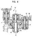
- Figure 8 shows the speed change mechanism section 10 in a cheese winding device.
- the traverse speed of the traverse device T may be constant, eliminating the needs for the rotating plate 14.
- a clutch hole 13a is disposed in the input gear 13 to constitute a ball clutch device between the input gear 13 and the output gear 15.
- the speed change mechanism section 10 in Figure 4 can be used for cheese winding packages by arranging the input shaft 11 and the rotating shat 12 on the same axis without eccentricity.
- the adjustment of the eccentric distance is one important element for synchronizing the operation of the traverse device T with the operation of the winding device A.
- the adjustment of synchronism between the traverse device T and the drum 6 of the winding device A is described.
- the guide grooves 7, 7 for preventing from yarn stitching are formed near the respective lateral ends of the surface of the drum 6 and in part of the circumference of the drum 6. The operation for guiding the yarn through the guide grooves 7, 7 must be synchronized with the operation of the traverse device T.
- the traverse device may be, for example, of a rotatable blades type, which provides similar effects in the configuration comprising the above speed change mechanism section and the clutch mechanism.
- the traverse device Due to the above configuration, the traverse device according to the present invention has the following effects: In the automatic winder, the clutch device is interposed between the drive source and the traverse mechanism section, and when a yarn is knotted, the clutch device is disconnected to block power transmission to the traverse mechanism section. Thus, when a defect is found in the yarn and If the yarn is cut and knotted, the delivery of the yarn resulting from the reverse rotation operation of the traverse device is prevented to solve problems such as yarn delivery errors, thereby improving the operability of the winder apparatus.
- the clutch device is interposed between the drive source and the traverse mechanism section, the clutch device can be connected only with a set phase, and the rotational movement of the drum of the winding device synchronizes with the reciprocating movement of the traverse mechanism section.
- This configuration enables synchronism between the state where the yarn, which is reciprocated in the traverse device, is located at the laterally opposite ends and the state where the yarn is guided to the yarn stitching preventing guide grooves provided in the drum of the winding device. Even if driving is transmitted without the synchronism, no drive force is transmitted to the traverse device, and the traverse device cannot be driven until these states synchronize with each other, thereby enabling a smooth and stable winding process.
- the clutch device comprises the ball clutch comprising the output gear having the plurality of gears buried therein and the clutch plate having the plurality of clutch holes, and the output gear and the clutch plate mesh with each other only with a set phase.
Landscapes
- Engineering & Computer Science (AREA)
- Textile Engineering (AREA)
- Quality & Reliability (AREA)
- Spinning Or Twisting Of Yarns (AREA)
- Winding Filamentary Materials (AREA)
Applications Claiming Priority (2)
| Application Number | Priority Date | Filing Date | Title |
|---|---|---|---|
| JP11002036A JP2000198621A (ja) | 1999-01-07 | 1999-01-07 | 自動ワインダのトラバ―ス装置 |
| JP203699 | 1999-01-07 |
Publications (2)
| Publication Number | Publication Date |
|---|---|
| EP1018479A2 true EP1018479A2 (fr) | 2000-07-12 |
| EP1018479A3 EP1018479A3 (fr) | 2001-01-31 |
Family
ID=11518114
Family Applications (1)
| Application Number | Title | Priority Date | Filing Date |
|---|---|---|---|
| EP99124772A Withdrawn EP1018479A3 (fr) | 1999-01-07 | 1999-12-13 | Dispositif de trancannage pour bobinoir automatique |
Country Status (2)
| Country | Link |
|---|---|
| EP (1) | EP1018479A3 (fr) |
| JP (1) | JP2000198621A (fr) |
Cited By (5)
| Publication number | Priority date | Publication date | Assignee | Title |
|---|---|---|---|---|
| CN101898705A (zh) * | 2010-05-18 | 2010-12-01 | 中国电子科技集团公司第四十研究所 | 丝带收卷机换挡机构 |
| CN112429589A (zh) * | 2020-10-14 | 2021-03-02 | 孙翠平 | 一种消防水带快速收卷装置 |
| CN112499380A (zh) * | 2020-12-16 | 2021-03-16 | 西格码电气股份有限公司 | 一种电力工程用自动化收线装置及其使用方法 |
| US11117737B2 (en) | 2012-11-12 | 2021-09-14 | Southwire Company, Llc | Wire and cable package |
| CN113882043A (zh) * | 2021-11-04 | 2022-01-04 | 常州市鹤鹏机械制造有限公司 | 一种捻线机用升降减速箱 |
Citations (5)
| Publication number | Priority date | Publication date | Assignee | Title |
|---|---|---|---|---|
| US3310246A (en) * | 1963-12-16 | 1967-03-21 | Mcclean Anderson Inc | Strand winding machine |
| FR1519822A (fr) * | 1967-02-14 | 1968-04-05 | Mecaniques Verdol Soc D | Perfectionnements aux dispositifs à cylindre de double appel pour l'industrie textile |
| US3397850A (en) * | 1966-10-31 | 1968-08-20 | Engineering Technology Inc | Filament winding apparatus |
| EP0510829A1 (fr) * | 1991-04-25 | 1992-10-28 | Rieter-Scragg Limited | Dispositif de bobinage |
| EP0834462A2 (fr) * | 1996-10-01 | 1998-04-08 | Murata Kikai Kabushiki Kaisha | Dispositif de bobinage |
-
1999
- 1999-01-07 JP JP11002036A patent/JP2000198621A/ja active Pending
- 1999-12-13 EP EP99124772A patent/EP1018479A3/fr not_active Withdrawn
Patent Citations (5)
| Publication number | Priority date | Publication date | Assignee | Title |
|---|---|---|---|---|
| US3310246A (en) * | 1963-12-16 | 1967-03-21 | Mcclean Anderson Inc | Strand winding machine |
| US3397850A (en) * | 1966-10-31 | 1968-08-20 | Engineering Technology Inc | Filament winding apparatus |
| FR1519822A (fr) * | 1967-02-14 | 1968-04-05 | Mecaniques Verdol Soc D | Perfectionnements aux dispositifs à cylindre de double appel pour l'industrie textile |
| EP0510829A1 (fr) * | 1991-04-25 | 1992-10-28 | Rieter-Scragg Limited | Dispositif de bobinage |
| EP0834462A2 (fr) * | 1996-10-01 | 1998-04-08 | Murata Kikai Kabushiki Kaisha | Dispositif de bobinage |
Cited By (8)
| Publication number | Priority date | Publication date | Assignee | Title |
|---|---|---|---|---|
| CN101898705A (zh) * | 2010-05-18 | 2010-12-01 | 中国电子科技集团公司第四十研究所 | 丝带收卷机换挡机构 |
| US11117737B2 (en) | 2012-11-12 | 2021-09-14 | Southwire Company, Llc | Wire and cable package |
| US11858719B2 (en) | 2012-11-12 | 2024-01-02 | Southwire Company, Llc | Wire and cable package |
| CN112429589A (zh) * | 2020-10-14 | 2021-03-02 | 孙翠平 | 一种消防水带快速收卷装置 |
| CN112499380A (zh) * | 2020-12-16 | 2021-03-16 | 西格码电气股份有限公司 | 一种电力工程用自动化收线装置及其使用方法 |
| CN112499380B (zh) * | 2020-12-16 | 2023-04-07 | 西格码电气股份有限公司 | 一种电力工程用自动化收线装置 |
| CN113882043A (zh) * | 2021-11-04 | 2022-01-04 | 常州市鹤鹏机械制造有限公司 | 一种捻线机用升降减速箱 |
| CN113882043B (zh) * | 2021-11-04 | 2022-10-21 | 常州市鹤鹏机械制造有限公司 | 一种捻线机用升降减速箱 |
Also Published As
| Publication number | Publication date |
|---|---|
| JP2000198621A (ja) | 2000-07-18 |
| EP1018479A3 (fr) | 2001-01-31 |
Similar Documents
| Publication | Publication Date | Title |
|---|---|---|
| EP0873962B1 (fr) | Bobinoir duel d'axe pour fibres optiques avec filetage et enroulement automatique | |
| EP1717182B1 (fr) | Dispositif d'élimination des relâchements de fil dans une machine textile | |
| US3749327A (en) | Thread packaging device with intermediate thread storage means | |
| CN102275774B (zh) | 卷取单元及具备该卷取单元的纱线卷取机 | |
| JPH11217158A (ja) | 巻取り装置 | |
| JP4155642B2 (ja) | 連続的に走入する糸を案内しかつ切断する装置及び方法 | |
| EP1018479A2 (fr) | Dispositif de trancannage pour bobinoir automatique | |
| EP1457446B9 (fr) | Dispositif de réglage de tension et d'élimination des relâchements de fil pour un dispositif de bobinage | |
| JP2007112625A (ja) | 繊維機械用巻取り装置 | |
| JP3749768B2 (ja) | 綾巻ボビンを製造する繊維機械 | |
| EP2749515A2 (fr) | Dispositif de stockage de fil et unité de filage | |
| TWI548584B (zh) | 捲線機及其操作方法 | |
| JP2003049333A (ja) | 自動玉揚げ機 | |
| EP0834462B1 (fr) | Dispositif de bobinage | |
| EP1561717B1 (fr) | Métier à filer avec un dispositif pour bobiner d'une réserve de fil sur une bobine vide | |
| JPH05162924A (ja) | 糸条巻取装置 | |
| JPH10250938A (ja) | ベルトトラバース装置 | |
| JP3681819B2 (ja) | フランジ付ボビンの巻糸装置 | |
| JP2761943B2 (ja) | タレット型巻糸装置 | |
| JPH08173671A (ja) | 下糸巻回装置 | |
| EP3746387B1 (fr) | Procédé permettant de positionner précisément une broche dans un enrouleur automatique de type à tourelle | |
| JP2782554B2 (ja) | タレット型巻糸装置 | |
| JP3675848B2 (ja) | タレット型巻取機の糸切替装置 | |
| JPH07246297A (ja) | ミシンの下糸巻回装置 | |
| JPH10338418A (ja) | ベルトトラバース装置 |
Legal Events
| Date | Code | Title | Description |
|---|---|---|---|
| PUAI | Public reference made under article 153(3) epc to a published international application that has entered the european phase |
Free format text: ORIGINAL CODE: 0009012 |
|
| AK | Designated contracting states |
Kind code of ref document: A2 Designated state(s): CH DE LI |
|
| AX | Request for extension of the european patent |
Free format text: AL;LT;LV;MK;RO;SI |
|
| PUAL | Search report despatched |
Free format text: ORIGINAL CODE: 0009013 |
|
| AK | Designated contracting states |
Kind code of ref document: A3 Designated state(s): AT BE CH CY DE DK ES FI FR GB GR IE IT LI LU MC NL PT SE |
|
| AX | Request for extension of the european patent |
Free format text: AL;LT;LV;MK;RO;SI |
|
| 17P | Request for examination filed |
Effective date: 20010423 |
|
| AKX | Designation fees paid |
Free format text: CH DE LI |
|
| 17Q | First examination report despatched |
Effective date: 20020930 |
|
| STAA | Information on the status of an ep patent application or granted ep patent |
Free format text: STATUS: THE APPLICATION HAS BEEN WITHDRAWN |
|
| 18W | Application withdrawn |
Withdrawal date: 20021118 |