EP0834462A2 - Dispositif de bobinage - Google Patents
Dispositif de bobinage Download PDFInfo
- Publication number
- EP0834462A2 EP0834462A2 EP97115964A EP97115964A EP0834462A2 EP 0834462 A2 EP0834462 A2 EP 0834462A2 EP 97115964 A EP97115964 A EP 97115964A EP 97115964 A EP97115964 A EP 97115964A EP 0834462 A2 EP0834462 A2 EP 0834462A2
- Authority
- EP
- European Patent Office
- Prior art keywords
- traverse
- speed change
- yarn
- gear
- winding
- Prior art date
- Legal status (The legal status is an assumption and is not a legal conclusion. Google has not performed a legal analysis and makes no representation as to the accuracy of the status listed.)
- Granted
Links
Images


Classifications
-
- B—PERFORMING OPERATIONS; TRANSPORTING
- B65—CONVEYING; PACKING; STORING; HANDLING THIN OR FILAMENTARY MATERIAL
- B65H—HANDLING THIN OR FILAMENTARY MATERIAL, e.g. SHEETS, WEBS, CABLES
- B65H54/00—Winding, coiling, or depositing filamentary material
- B65H54/02—Winding and traversing material on to reels, bobbins, tubes, or like package cores or formers
- B65H54/28—Traversing devices; Package-shaping arrangements
- B65H54/2821—Traversing devices driven by belts or chains
- B65H54/2824—Traversing devices driven by belts or chains with at least two traversing guides travelling in opposite directions
-
- B—PERFORMING OPERATIONS; TRANSPORTING
- B65—CONVEYING; PACKING; STORING; HANDLING THIN OR FILAMENTARY MATERIAL
- B65H—HANDLING THIN OR FILAMENTARY MATERIAL, e.g. SHEETS, WEBS, CABLES
- B65H2701/00—Handled material; Storage means
- B65H2701/30—Handled filamentary material
- B65H2701/31—Textiles threads or artificial strands of filaments
Definitions
- the present invention relates to a winding device for forming a package by winding while traversing yarn and more specifically, relates to a winding device of the type that traverses yarn by a traverse system having a set of traverse belts that move in opposite directions to each other.
- Winding devices for forming a package by winding yarn are generally provided with a winding system connected to a drive source such as a motor or the like and having a friction drum that rotates in contact with the package, and a traverse system for traversing the yarn to be wound on the package, and are arranged such that a package is formed by winding the yarn on a paper tube or the like by the winding system while traversing.
- Conventional winding devices are arranged such that the friction drum that transmits rotational drive force by contacting the package performs traversing of the yarn.
- This device is arranged with a traverse groove in the friction drum and the yarn is traversed along the traverse groove simultaneous with winding of the yarn by rotating the drum.
- Types of package include cylindrical cheese packages, conical or truncated conical cone packages and the like.
- the winding device of the type which uses a friction drum with a traverse groove performs simultaneous winding of the yarn and traversing by a single friction drum, when there are to be specification changes such as from a cheese package to a cone package or when the winding angle on the cone package is to be changed, it is necessary to exchange the friction drum corresponding to each type of spacification.
- the friction drum must be exchanged, the operation is complicated and thus the operational efficiency is decreased.
- the present invention is a winding device provided with a winding system connected to a drive source such as a motor or the like and having a friction drum that rotated in contact with the package and a traverse system for traversing the yarn to be wound on the package, wherein the traverse system is a belt traverse system having a set of traverse belts that move in opposite directions to each other and which is connected to the winding system via a speed change system arranged being an arrangement capable of adjusting the traverse speed.
- the speed change system may have non-aligned shafts which are able to adjust the amount of eccentricity.
- the present invention is a winding device provided with a speed change system input with drive force from a motor or the like and a traverse system connected to the speed change system and having a set of traverse belts that move in opposite directions to each other, wherein the means for transmitting the drive force from the speed change system to the traverse system comprises the engagement of gears and the traverse system is arranged so as to be removable.
- the part that connects the traverse system and speed change system may be positioned between the shaft of the input gear on the traverse system and the shaft of the output gear on the speed change system.
- the input gear on the traverse system and the output gear on the speed change system are spur gears.
- the present invention is a winding device provided with a drive transmission part input with a drive force from a motor or the like and a traverse system having a set of traverse belts that move in opposite directions to each other by connection to the drive transmission part, wherein the means for transmitting the drive force from the drive transmission part to the traverse system comprises the engagement of gears and the traverse system is arranged so as to be removable.
- Figure 1 is a perspective view showing a schematic arrangement of one example of the winding device being a first embodiment of the present invention.
- Figure 2A is a partially sectioned front view in one example of the speed change system used on the winding device being a first embodiment of the present invention with and Figure 2B is a side view of the main part.
- Figure 3 is a perspective view showing a schematic arrangement of the winding device being a second embodiment of the present invention.
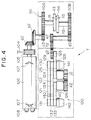
- Figure 4 is a front view showing a schematic arrangement of the winding device being a second embodiment of the present invention.
- Figure 5 is a top view showing a schematic arrangement of the winding device being a second embodiment of the present invention.
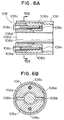
- Figure 6A is a front sectional view of the main part in an example of the drum fixed structure on the winding device being a second embodiment of the present invention and Figure 6B is a side sectional view along the line VIB-VIB.
- Figure 7 is a perspective view showing an auto-winder being one example of the winding device being a second embodiment of the present invention.
- Figure 8 is a perspective view showing a removable belt traverse being the main part of Figure 7.
- Figure 1 shows a schematic arrangement of one example of a winding device A being a first embodiment of the present invention.
- a winding system 1 comprises a pulley 3 connected to the drive shaft of a motor 2 being the drive source, a pulley 5 to which the drive force is transmitted from the pulley 3 by a belt 4 and a friction drum 6 (hereafter, referred to simply as a drum) connected to the pulley 5 and that contacts the periphery of a package P.
- the drive force of the motor 2 is transmitted to the drum 6 via the pulley 3, belt 4 and pulley 5 and winding of a yarn S is performed by applying a rotational drive force to the package P by the contact rotation of this drum 6.
- a guide groove 7 for preventing yarn stitching is arranged in part of the circumferential direction close to the left and right ends of the surface of the drum 6.
- the drive force of the motor 2 is transmitted to the traverse system 20 via the speed change system 10 by the system described hereafter.
- the rotational drive force of the motor 2 is transmitted to the input side gear 10A of the speed change system 10 via a gear a1 linked to the rotation shaft of the drum, a gear b1 that engages with the gear a1 and a gear c1 linked to the gear b1 and on the same shaft. Due to the rotational driving of the input side gear 10A, the output side gear 10b rotates at a under predetermined speed change conditions and this speed varying rotational drive force is transmitted to the traverse system 20.
- the traverse system 20 is for moving a set (two) of synchronous toothed belts 22,23 (traverse belts) arranged horizontally above each other and each provided with traverse guides 21 that catch the yarn S, in opposite directions to each other ad comprises synchronous toothed belts 22,23,24,25 pulleys 26,27,28,29,30,31,32,33,34 and gears d,e,f.
- pulleys 28 and 30 arranged on the same shaft at one end of one set of synchronous toothed belts 22,23 rotate in unison but pulley 29 rotates freely with respect to those.
- the pulleys 32 and 33 arranged on the same shaft at the other end of one set of synchronous toothed belts 22,23 rotate in unison but pulley 31 rotates freely with respect to these. Due to this arrangement, one set of synchronous toothed belts 22,23 arranged on concentric pulleys arranged at both ends of the traverse width are able to move in opposite directions to each other.
- the rotational drive force of the output side gear 10B of the speed change system 10 is output to the gear d1 making the pulley 26 connected to the same shaft rotate. Due to the rotation of the pulley 26, the synchronous toothed belt 24 arranged on the pulleys 27,28 is driven. The aforementioned pulley 28 rotates the pulley 30 connected to the same shaft and drives the synchronous toothed belt 22 arranged on the pulley 31 in the direction of the arrow.
- the traverse system 20 is able to reciprocally move the yarn S within a predetermined range equivalent to the winding width of the package P due to the transfer of the yarn S from the traverse guide 21 of the upper synchronous toothed belt 22 to the traverse guide (not shown in the drawings) of the lower synchronous toothed belt 23.
- the rotation shaft 11 of the input side gear 10A and the rotation shaft 12 of the output side gear 10B on the speed change system 10 are arranged as non-aligned shafts where the center of rotation is eccentric.
- the rotation shaft 11 of the input side gear 10A and the rotation shaft 12 of the output side gear 10B are positioned such that the centers of rotation of each r 1 ,r 2 are eccentric by the distance X and furthermore, a first disk 13 is arranged on the tip of the rotation shaft 11 of the input side gear 10A and a second disk 14 is arranged on the tip of the rotation shaft 12 of the output side gear 10B.
- a pin 15 fixed in a suitable place in the first disk 13 connects both disks 13,14 by being movably insertable into a long hole 16 arranged in the second disk 14.
- the rotational drive force of the input side gear 10A is transferred to the output side gear 10B by the pin 15 connecting the first disk 13 and the second disk 14.
- the distance X the distance from the center of rotation r 2 of the second disk 14 to the pin 15 gradually changes while the first disk 13 is rotating.
- the second disk 14 makes one revolution at a non-uniform speed. Accordingly, as the rotational velocity of the rotational drive force output to the traverse system 20 through the output side gear 10B connecting to the second disk 14 changes over a fixed cycle, the movement speed of the traverse belts 21,22, in short, the traverse speed increases and decreases over a fixed cycle.
- one revolution is one cycle of speed variation.
- the traversing of the yarn S completes one reciprocal movement for each one revolution of the input/output side gears 10A,10B of the speed change system 10 and the intended cone package may be obtained if the traverse speed is maximized at the smallest diameter part on the cone package and minimized at the largest diameter part of the package P.
- the speed charge ratio is defined as (R+X)/(R-X).
- the speed change ratio is set around 1.3 but by changing the value of the amount of eccentricity X, the formation of a cone package having the desired shape corresponding to each type of specifications is possible by changing the speed change ratio non-graduatedly. Furthermore, if it is possible to set the speed change ratio to 1, the formation of a cheese package is also possible.
- the changing of the speed change ratio is possible by fixing the position of the input side gear 10A and first disk 13 and increasing or reducing the amount of eccentricity X by moving the output side gear 10B and second disk 14 in a direction at right angles to the rotation shaft.
- the position of the output side gear 10B by changing the position of the output side gear 10B, the position of the pulley 26 and the gear d1 that inputs rotational drive force into the traverse system 20 must also be changed.
- a tension pulley (not shown in the drawings) is arranged with respect to the synchronous toothed belt 24 and it is preferable to adjust the belt tension using this.
- the first embodiment of the present invention is not limited to that stated here and does not disclude suitable modifications in response to various conditions.
- a wing traverse system or equi-velocity cam traverse system may be utilized as a traverse device.
- Figure 3 shows a schematic arrangement of one example of the winding device A being a second embodiment of the present invention.
- This winding device A is provided with a drive source such as a motor 102 or the like, a pulley 105 to which the drive force is transmitted via a belt 104 from a pulley 103 linked to a drive shaft 102a of the motor 102, and a friction drum 106 (hereafter, referred to simply as a drum 106) connected to a rotation shaft 106a of the pulley 105 and is in contact with the periphery of the package P.
- Guide grooves 107 for preventing yarn stitching are formed in part of the circumferential direction near both the left and right ends on the periphery of the drum 106.
- the drive force of the motor 102 is transmitted from the pulley 103 to the pulley 105 via the belt 104 and the rotational drive force is transmitted from that pulley 105 to the speed charge system 10 of the traverse device T and drum 106.
- the drum 106 is arranged such that the yarn S is wound with a tapered paper tube Q as the core by rotating the package P.
- the traverse device T comprises speed change system 110 and traverse system 120 connected to this.
- the system that transmits the drive force of the motor 102 from the speed change system 110 of the traverse device T to the traverse system 120 is as described hereafter.
- the rotational drive force of the motor 102 is input into the speed change system 110 from the gear a2 linked to the rotation shaft 106a of the drum 106.
- the secondary side gear 110B rotates under predetermined speed change conditions by the system described hereafter and that speed varied rotational drive force rotates the gear d2 that engages with the secondary side gear 110B and the gear e2 linked to the same shaft as gear d2. Also, the drive force is transmitted to the input gear g2 of the traverse system 120 through the output gear f2 that engages with the gear e2.
- the traverse system 120 rotates the traverse belts 121,122 arranged parallel above each other and provided with traverse guides 140 on each that connect with the yarn S, in opposite directions to each other and as shown in Figure 5, is arranged as a unit removable by a bolt 119 from a frame 117,118 that supports the speed change system 110.
- the arrangement of the traverse system 120 comprises not only traverse belts 121,122 but also synchronous toothed belts 125,126, pulleys 123,124,128-134 and input gear g2, gears j2 and k2. It should be noted that gears j2 and k2 are mounted at a position from which a removing operation is possible from the outer side.
- the upper traverse belt 121 is arranged between the pulleys 130,131 and the lower traverse belt 122 is arranged between pulleys 129,132.
- the pulley 123 is linked to the same shaft as the input gear g2 that engages with output gear f2 of the speed change system 110 and a synchronous toothed belt 125 is arranged between this pulley 123, the pulley 124 and pulley 128.
- the synchronous toothed belt 126 is arranged between the pulleys 133,134.
- pulleys 128,129,130 Of the pulleys 128,129,130 arranged on the same shaft, the pulleys 128 and 130 rotate in unison and the pulley 129 rotates freely with respect to the other two. Similarly, of the pulleys 131,132,133 arranged on the same shaft, the pulleys 132 and 133 rotate in unison and the pulley 131 rotates freely with respect to the other two. It should be noted that the aforementioned pulleys 128,129,130 arranged on the same shaft and the pulleys 131,132,133 are arranged so as to each be removable by a boss 141 and boss 142 respectively (refer to Figure 4).
- the tension pulleys 135-138 ommitted from Figures 3 and 4 are inserted in Figure 5 showing the schematic arrangement of the traverse system 120 when viewed from above.
- the tension pulley 135 is for adjusting the tension of the upper traverse belt 121
- the tension pulley 136 is for adjusting the tension of the lower traverse belt 122
- the tension pulley 137 is for adjusting the tension of the synchronous toothed belt 125 arranged between the pulleys 123,124,128
- the tension pulley 138 is for adjusting the tension of the synchronous toothed belt 126 arranged between the pulleys 133,134.
- the rotational drive force input into the input gear g2 from the output gear f2 of the speed change system 10 is transmitted to the pulley 123. Due to this, the synchronous toothed belt 125 arranged between the pulleys 123,124,128 is driven and the traverse belt 121 arranged between the pulleys 130,131 moves in the direction of the arrow (refer to Figure 3) due to the rotation of the pulley 130 linked to the same shaft as pulley 128.
- the gear j2 linked to the same shaft rotates and the gear k2 that engages with this is rotated in the opposite direction.
- the pulley 134 linked to the same shaft rotates
- the pulley 133 rotates via the synchronous toothed belt 126.
- the pulley 132 linked to the same shaft rotates and the traverse belt 122 arranged between the pulleys 129,132 moves in the opposite direction to the aforementioned traverse belt 121.
- the upper and lower traverse belts 121,122 move in opposite directions to each other. Then due to the transfer of the yarn S between the upper and lower traverse guides 140,140 arranged on each of the traverse belts 121,122 respectively, the yarn S is able to be reciprocally moved within a predetermined range equivalent to the winding width of the package P.
- the changing of the speed change ratio is possible by fixing the position of the primary side gear 110A and first disk 113 and increasing or reducing the amount of eccentricity by moving the secondary side gear 110B and second disk 114 in a direction at right angles to the rotation shaft.
- the spacing of the gear e2 and the input gear g2 of the traverse system 120 changes.
- changing the position of the input gear g2 is difficult.
- the output gear f2 is movable and moreover, it's diameter is larger than the spacing between the gear e2 and gear g2 and by changing the gear position such that it suitable engages corresponding to the increase or decrease in the spacing between the gears e2,g2, this problem is solved.
- the aforementioned transfer position adjustment 1 ⁇ is performed as described hereafter.
- the traverse system 120 is removed from the traverse device T and the gear k2 removed.
- the desired tension is then applied to each of the traverse belts 121,122 and synchronous toothed bolts 125,126 arranged between the pulleys by the tension pulleys 136-138 (refer to Figure 5) and the traverse guides 140,140 are adjusted such that one of the traverse belts 121,122 overlap at one end in the vertical direction.
- This state is then held by a suitable tool and if the gear k2 is attached and engages with the gear j2, the transfer position of the yarn S between the traverse guides 140,140 is fixed in the correct state. It should be rated that the aforementioned operation may be performed with the gear j2 being removable.
- the phase of the speed change system 110 is adjusted such that it is the same as the traverse system 120.
- the positional relationship between the primary side gear 110A and secondary side gear 110B is adjusted such that the speed variation conditions are in alignment with the traverse guide position after adjustment 1 ⁇ (the rotational velocity has been either maximized or minimized). If a marking that shows the position where the rotational velocity of the secondary side gear 110B is at a maxim (or minimum) , is performed on the frame or the like that supports the speed change system 110, the aforementioned adjustment operation is extremely simple.
- the traverse system 120 that has been held in this state by a suitable tool is fixed to the predetermined place on the frame 118 (refer to Figure 5) by 3 or 4 bolts 119 and the input gear g2 is engaged with the output gear f2. Due to this, a state where the yarn transfer timing and speed variation of the traverse speed have been correctly adjusted may be obtained.
- the traverse guide is held in the yarn transfer position and the position of the drum 106 is adjusted and fixed so that it is in alignment with this held state.
- the drum 106 of the present embodiment is arranged such that it may be fixed at a desired angle (phase) with respect to the rotation shaft 106a by a tapered fixing member 108 positioned on the end as shows in Figures 4 and 6.
- the fixing member 108 comprises first taper members 108a,108a that contact the outer periphery of the rotating shaft 106a, second taper members 108b,108b that contact the inner periphery of the drum 106, and bolts 108c,108c.
- Each member is positioned in two part sets axially symmetric about the rotation shaft 106a.
- a hole 108d into which may be freely inserted the bolt 108c is formed in the first taper member 108a and a screw hole 108e into which the bolt 108c may be screwed is formed in the second taper member 108b.
- the bolt 108c is inerted into the hole 108d of the first taper member 108a and by tightening by screwing into the screw hole 108e of the second taper member 108b, the second taper member 108b is pulled by the first taper member 108a. Due to this, both taper members 108a,108b slide in contact with each other along a slop, the first taper member 108a presses the outer periphery of the rotation shaft 106a, the second taper member 108b presses the inner periphery of the drum 106 and as a result, the drum 106 and rotation shaft 106a are fixed so as to rotate in unison.
- FIG 7 shows the entire arrangement of an auto-winder 150 being one example of the winding device being a second embodiment of the present invention and Figure 8 shows those main parts.
- the auto-winder 150 shows forms a cone package by winding the yarn S on a tapered paper tube Q held so as to be removable by the upper most cradle 151 while unwinding the yarn S from an supply yarn package 160.
- the auto-winder of figures 8 and 9 may be used as winding devices being the first embodiment of the present invention.
- the part (refer to Figure 8), of the belt traverse device T, comprising the drum 106 that applies a rotational drive force to the paper tube Q and the traverse system 120 that traverses the yarn S to the left and right is an arrangement removable as a single unit by a bolt from the frame 159 of the winder 150 and the speed change system 110 and a mechanical element for transmitting the rotational drive force of the motor 102 to that speed change system 110 (in short, belt 104, pulley 105 and gears a2,b2,c2) are stored inside the frame 159.
- the marking for aligning the phase of the speed change system 110 to the traverse system 120 is easily visible from the outer side, it is preferable to arrange a winder or the like (not shown in the drawings) in a location on the frame 159.
- the yarn S unwound from the supply yarn package 160 is rewound onto the tapered paper tube Q rotated by the drum 106 after being made to follow the guide 157.
- the yarn S at this time is traversed to the left and right while the speed is increased and decreased in the uniform cycle ideal for forming a cone package.
- a yarn defect detector 153 inspects whether there are any yarn defects in the yarn Y and furthermore, a tensor 156 controls the tension of the yarn S.
- the yarn defect detector 153 detects some kind of defect or abnormality in the yarn S
- the driving of the drum 106 by the motor 102 is stopped and the yarn S is cut by a cutter provided on the yarn defect detector 153.
- the supply side part of the cut yarn S (lower yarn) is sucked by the continuously sucking lower yarn sucking mouth 155.
- the winding side part of the cut yarn S (upper yarn) is wound on to the paper tube Q by the drum 106 rotating by inertial rotation.
- the yarn S is slightly payed out by reverse rotating the drum 106 and after grabbing the upper yarn be rotating the upper yarn suction member 158 upwards, the grasped upper yarn is guided to the yarn piecing device 152 by rotating the upper yarn suction member 158 downwards.
- the winding device being a second embodiment of the present invention may be provided with a belt traverse device not possessing a speed change system specifically for a cheese winding.
- a brief adjustment operation may be completed by simply engaging the output gear with the input gear by connecting the traverse system to the drive transmission part and thus is extremely simple.
- the present invention does not preclude suitable modifications corresponding to other conditions.
- the winding device of the present invention is able to reliably form a cone package by a simple arrangement. Furthermore, by changing the speed of the traverse system, a winding state suitable for each of the small diameter part and large diameter part when forming a package is realised. There is no increase in the mechanical load on the winding system and there is no danger of slippage being generated between the package and friction drum.
- the traverse system as a belt traverse system that may be arranged as a low inertia rotating member, the problems such as mechanical load and noise may be reduced and speed variation may be more quickly and more relaiably performed by the speed change system.
- the present invention is a simple arrangement achieved by utilizing a system whereby the speed change ratio is changed by increasing or decreasing the amount of eccentricity, it is possible to non-graduatedly change the speed change ratio on an identical device.
- the present invention has a removable traverse system and as the means for transmission of the drive force from the speed change system to the traverse system is comprised of engaged gears, after independently performing the phase adjustments of each of the traverse system and speed change system, botthe phases of both may be aligned by simply mounting the traverse system and engaging the gears. Accordingly, the number of necessary operations is decreased and results in operation only at the front of the device thus making the yarn transfer adjustment operations extremely simple. Furthermore, as a result, the time when the device must be stopped for maintenance is reduced.
- the present invention is also effective with winding devices provided with a belt traverse device not possessing a speed change system.
Applications Claiming Priority (3)
| Application Number | Priority Date | Filing Date | Title |
|---|---|---|---|
| JP26073396 | 1996-10-01 | ||
| JP26073396A JPH10109823A (ja) | 1996-10-01 | 1996-10-01 | 巻取装置 |
| JP260733/96 | 1996-10-01 |
Publications (3)
| Publication Number | Publication Date |
|---|---|
| EP0834462A2 true EP0834462A2 (fr) | 1998-04-08 |
| EP0834462A3 EP0834462A3 (fr) | 1998-05-27 |
| EP0834462B1 EP0834462B1 (fr) | 2002-05-22 |
Family
ID=17352002
Family Applications (1)
| Application Number | Title | Priority Date | Filing Date |
|---|---|---|---|
| EP19970115964 Expired - Lifetime EP0834462B1 (fr) | 1996-10-01 | 1997-09-13 | Dispositif de bobinage |
Country Status (3)
| Country | Link |
|---|---|
| EP (1) | EP0834462B1 (fr) |
| JP (1) | JPH10109823A (fr) |
| DE (1) | DE69712695T2 (fr) |
Cited By (4)
| Publication number | Priority date | Publication date | Assignee | Title |
|---|---|---|---|---|
| EP1018479A2 (fr) * | 1999-01-07 | 2000-07-12 | Murata Kikai Kabushiki Kaisha | Dispositif de trancannage pour bobinoir automatique |
| EP2404855A3 (fr) * | 2010-07-09 | 2015-11-04 | Murata Machinery, Ltd. | Dispositif de bobinage de fil |
| CN108190625A (zh) * | 2017-12-27 | 2018-06-22 | 河南华通电缆股份有限公司 | 一种生产电缆电线设备的双电机电缆托架装置的组装方法 |
| CN114157110A (zh) * | 2021-12-14 | 2022-03-08 | 佛山市顺德区乐普达电机有限公司 | 一种食品加工电机生产用全自动绕线结构 |
Citations (7)
| Publication number | Priority date | Publication date | Assignee | Title |
|---|---|---|---|---|
| FR49280E (fr) * | 1938-01-12 | 1939-02-16 | Ryo Catteau Ets | Dispositif de guidage du fil dans les bobinoirs à fils croisés |
| US3491604A (en) * | 1968-02-12 | 1970-01-27 | Cass B Levi | Device for modifying rotary motion |
| GB2058860A (en) * | 1979-09-25 | 1981-04-15 | Terrell Mach Co | Apparatus and Method for Winding Yarn to Form a Package |
| JPS594571A (ja) * | 1982-06-30 | 1984-01-11 | Asahi Chem Ind Co Ltd | 糸条トラバ−ス装置 |
| GB2138094A (en) * | 1983-04-12 | 1984-10-17 | Cefin Spa | Device for converting uniform rotary motion into variable speed rotary motion |
| DE3603803A1 (de) * | 1986-02-07 | 1987-08-13 | Schlafhorst & Co W | Kreuzspulautomat |
| DE4310905A1 (de) * | 1993-04-02 | 1994-10-06 | Schlafhorst & Co W | Verfahren und Vorrichtung zur Fadenverlegung auf einer Kreuzspule |
-
1996
- 1996-10-01 JP JP26073396A patent/JPH10109823A/ja active Pending
-
1997
- 1997-09-13 DE DE1997612695 patent/DE69712695T2/de not_active Expired - Fee Related
- 1997-09-13 EP EP19970115964 patent/EP0834462B1/fr not_active Expired - Lifetime
Patent Citations (7)
| Publication number | Priority date | Publication date | Assignee | Title |
|---|---|---|---|---|
| FR49280E (fr) * | 1938-01-12 | 1939-02-16 | Ryo Catteau Ets | Dispositif de guidage du fil dans les bobinoirs à fils croisés |
| US3491604A (en) * | 1968-02-12 | 1970-01-27 | Cass B Levi | Device for modifying rotary motion |
| GB2058860A (en) * | 1979-09-25 | 1981-04-15 | Terrell Mach Co | Apparatus and Method for Winding Yarn to Form a Package |
| JPS594571A (ja) * | 1982-06-30 | 1984-01-11 | Asahi Chem Ind Co Ltd | 糸条トラバ−ス装置 |
| GB2138094A (en) * | 1983-04-12 | 1984-10-17 | Cefin Spa | Device for converting uniform rotary motion into variable speed rotary motion |
| DE3603803A1 (de) * | 1986-02-07 | 1987-08-13 | Schlafhorst & Co W | Kreuzspulautomat |
| DE4310905A1 (de) * | 1993-04-02 | 1994-10-06 | Schlafhorst & Co W | Verfahren und Vorrichtung zur Fadenverlegung auf einer Kreuzspule |
Non-Patent Citations (1)
| Title |
|---|
| PATENT ABSTRACTS OF JAPAN vol. 008, no. 087 (M-291), 20 April 1984 -& JP 59 004571 A (ASAHI KASEI KOGYO KK), 11 January 1984, * |
Cited By (6)
| Publication number | Priority date | Publication date | Assignee | Title |
|---|---|---|---|---|
| EP1018479A2 (fr) * | 1999-01-07 | 2000-07-12 | Murata Kikai Kabushiki Kaisha | Dispositif de trancannage pour bobinoir automatique |
| EP1018479A3 (fr) * | 1999-01-07 | 2001-01-31 | Murata Kikai Kabushiki Kaisha | Dispositif de trancannage pour bobinoir automatique |
| EP2404855A3 (fr) * | 2010-07-09 | 2015-11-04 | Murata Machinery, Ltd. | Dispositif de bobinage de fil |
| CN108190625A (zh) * | 2017-12-27 | 2018-06-22 | 河南华通电缆股份有限公司 | 一种生产电缆电线设备的双电机电缆托架装置的组装方法 |
| CN114157110A (zh) * | 2021-12-14 | 2022-03-08 | 佛山市顺德区乐普达电机有限公司 | 一种食品加工电机生产用全自动绕线结构 |
| CN114157110B (zh) * | 2021-12-14 | 2022-09-02 | 佛山市顺德区乐普达电机有限公司 | 一种食品加工电机生产用全自动绕线结构 |
Also Published As
| Publication number | Publication date |
|---|---|
| DE69712695T2 (de) | 2003-01-30 |
| EP0834462B1 (fr) | 2002-05-22 |
| EP0834462A3 (fr) | 1998-05-27 |
| DE69712695D1 (de) | 2002-06-27 |
| JPH10109823A (ja) | 1998-04-28 |
Similar Documents
| Publication | Publication Date | Title |
|---|---|---|
| EP1880964B1 (fr) | Dispositif de guide-fil haute fréquence pour la production de bobines avec déplacement modulé | |
| US20090134263A1 (en) | Method for Avoiding Ribbon Windings | |
| EP1457446B9 (fr) | Dispositif de réglage de tension et d'élimination des relâchements de fil pour un dispositif de bobinage | |
| JP3749768B2 (ja) | 綾巻ボビンを製造する繊維機械 | |
| EP0834462B1 (fr) | Dispositif de bobinage | |
| US4349160A (en) | Apparatus and method for winding yarn to form a package | |
| EP0902107B1 (fr) | Machine de torsion multiple | |
| US5277668A (en) | Gear transmissions, for textile machines | |
| JP2003049333A (ja) | 自動玉揚げ機 | |
| JPH08299763A (ja) | 中空糸膜の糸束製作方法及び巻取り整形機並びに送出装置 | |
| EP1018479A2 (fr) | Dispositif de trancannage pour bobinoir automatique | |
| JP4709347B2 (ja) | パッケージ交換の際に供給される糸を案内しかつ切断する装置及び方法 | |
| EP0060570B1 (fr) | Cylindre rainuré pour un bobinoir | |
| US6726142B2 (en) | Twist controlling device, rotatable nip and axial feed system | |
| EP0612683B1 (fr) | Machine d'enroulement de fils multiples | |
| JP2756831B2 (ja) | 精密巻取機 | |
| JPH05162924A (ja) | 糸条巻取装置 | |
| US4109877A (en) | Winding apparatus | |
| JP2780336B2 (ja) | 糸条の巻取体製造装置 | |
| JPH10250938A (ja) | ベルトトラバース装置 | |
| JP3675848B2 (ja) | タレット型巻取機の糸切替装置 | |
| JP2530545B2 (ja) | トラバ―ス装置 | |
| JPH10338418A (ja) | ベルトトラバース装置 | |
| JPH11236169A (ja) | 巻取装置 | |
| SU1655884A1 (ru) | Устройство дл намотки нитевидного материала |
Legal Events
| Date | Code | Title | Description |
|---|---|---|---|
| PUAI | Public reference made under article 153(3) epc to a published international application that has entered the european phase |
Free format text: ORIGINAL CODE: 0009012 |
|
| AK | Designated contracting states |
Kind code of ref document: A2 Designated state(s): CH DE IT LI |
|
| AX | Request for extension of the european patent |
Free format text: AL;LT;LV;RO;SI |
|
| PUAL | Search report despatched |
Free format text: ORIGINAL CODE: 0009013 |
|
| AK | Designated contracting states |
Kind code of ref document: A3 Designated state(s): AT BE CH DE DK ES FI FR GB GR IE IT LI LU MC NL PT SE |
|
| AX | Request for extension of the european patent |
Free format text: AL;LT;LV;RO;SI |
|
| 17P | Request for examination filed |
Effective date: 19980626 |
|
| AKX | Designation fees paid |
Free format text: CH DE IT LI |
|
| RBV | Designated contracting states (corrected) |
Designated state(s): CH DE IT LI |
|
| 17Q | First examination report despatched |
Effective date: 20000211 |
|
| GRAG | Despatch of communication of intention to grant |
Free format text: ORIGINAL CODE: EPIDOS AGRA |
|
| GRAG | Despatch of communication of intention to grant |
Free format text: ORIGINAL CODE: EPIDOS AGRA |
|
| GRAG | Despatch of communication of intention to grant |
Free format text: ORIGINAL CODE: EPIDOS AGRA |
|
| GRAH | Despatch of communication of intention to grant a patent |
Free format text: ORIGINAL CODE: EPIDOS IGRA |
|
| GRAH | Despatch of communication of intention to grant a patent |
Free format text: ORIGINAL CODE: EPIDOS IGRA |
|
| GRAA | (expected) grant |
Free format text: ORIGINAL CODE: 0009210 |
|
| REG | Reference to a national code |
Ref country code: CH Ref legal event code: EP |
|
| REF | Corresponds to: |
Ref document number: 69712695 Country of ref document: DE Date of ref document: 20020627 |
|
| REG | Reference to a national code |
Ref country code: CH Ref legal event code: NV Representative=s name: KIRKER & CIE SA |
|
| PLBE | No opposition filed within time limit |
Free format text: ORIGINAL CODE: 0009261 |
|
| STAA | Information on the status of an ep patent application or granted ep patent |
Free format text: STATUS: NO OPPOSITION FILED WITHIN TIME LIMIT |
|
| 26N | No opposition filed |
Effective date: 20030225 |
|
| PGFP | Annual fee paid to national office [announced via postgrant information from national office to epo] |
Ref country code: CH Payment date: 20060914 Year of fee payment: 10 |
|
| PGFP | Annual fee paid to national office [announced via postgrant information from national office to epo] |
Ref country code: IT Payment date: 20060930 Year of fee payment: 10 Ref country code: DE Payment date: 20060930 Year of fee payment: 10 |
|
| REG | Reference to a national code |
Ref country code: CH Ref legal event code: PL |
|
| PG25 | Lapsed in a contracting state [announced via postgrant information from national office to epo] |
Ref country code: LI Free format text: LAPSE BECAUSE OF NON-PAYMENT OF DUE FEES Effective date: 20070930 Ref country code: DE Free format text: LAPSE BECAUSE OF NON-PAYMENT OF DUE FEES Effective date: 20080401 Ref country code: CH Free format text: LAPSE BECAUSE OF NON-PAYMENT OF DUE FEES Effective date: 20070930 |
|
| PG25 | Lapsed in a contracting state [announced via postgrant information from national office to epo] |
Ref country code: IT Free format text: LAPSE BECAUSE OF NON-PAYMENT OF DUE FEES Effective date: 20070913 |