EP1014888B1 - Means of deploying a prosthesis - Google Patents
Means of deploying a prosthesis Download PDFInfo
- Publication number
- EP1014888B1 EP1014888B1 EP98922515A EP98922515A EP1014888B1 EP 1014888 B1 EP1014888 B1 EP 1014888B1 EP 98922515 A EP98922515 A EP 98922515A EP 98922515 A EP98922515 A EP 98922515A EP 1014888 B1 EP1014888 B1 EP 1014888B1
- Authority
- EP
- European Patent Office
- Prior art keywords
- prosthesis
- arrangement
- proximal
- distal
- control section
- Prior art date
- Legal status (The legal status is an assumption and is not a legal conclusion. Google has not performed a legal analysis and makes no representation as to the accuracy of the status listed.)
- Expired - Lifetime
Links
- 230000007246 mechanism Effects 0.000 claims description 48
- 238000003780 insertion Methods 0.000 claims description 16
- 230000037431 insertion Effects 0.000 claims description 16
- 229940030225 antihemorrhagics Drugs 0.000 claims description 11
- 239000003153 chemical reaction reagent Substances 0.000 claims description 11
- 230000000025 haemostatic effect Effects 0.000 claims description 11
- 239000002184 metal Substances 0.000 claims description 11
- 230000008602 contraction Effects 0.000 claims description 4
- 239000012530 fluid Substances 0.000 claims description 4
- 238000004891 communication Methods 0.000 claims description 2
- 239000006185 dispersion Substances 0.000 claims description 2
- 210000003090 iliac artery Anatomy 0.000 description 16
- 230000000717 retained effect Effects 0.000 description 16
- 210000000709 aorta Anatomy 0.000 description 14
- 239000000463 material Substances 0.000 description 14
- 238000000034 method Methods 0.000 description 13
- 210000002254 renal artery Anatomy 0.000 description 11
- 239000008280 blood Substances 0.000 description 8
- 210000004369 blood Anatomy 0.000 description 8
- 210000001105 femoral artery Anatomy 0.000 description 6
- 229920004934 Dacron® Polymers 0.000 description 5
- 230000004888 barrier function Effects 0.000 description 5
- 230000003447 ipsilateral effect Effects 0.000 description 5
- 239000005020 polyethylene terephthalate Substances 0.000 description 5
- 229920002994 synthetic fiber Polymers 0.000 description 5
- 230000000712 assembly Effects 0.000 description 4
- 238000000429 assembly Methods 0.000 description 4
- 208000007536 Thrombosis Diseases 0.000 description 3
- 239000002775 capsule Substances 0.000 description 3
- 230000014759 maintenance of location Effects 0.000 description 3
- 230000017531 blood circulation Effects 0.000 description 2
- 210000000056 organ Anatomy 0.000 description 2
- 230000008439 repair process Effects 0.000 description 2
- 238000007789 sealing Methods 0.000 description 2
- 206010002329 Aneurysm Diseases 0.000 description 1
- 241000785917 Savia Species 0.000 description 1
- 230000009471 action Effects 0.000 description 1
- 238000002583 angiography Methods 0.000 description 1
- 210000001367 artery Anatomy 0.000 description 1
- 230000008901 benefit Effects 0.000 description 1
- 210000004204 blood vessel Anatomy 0.000 description 1
- 238000010276 construction Methods 0.000 description 1
- 239000002872 contrast media Substances 0.000 description 1
- 230000000694 effects Effects 0.000 description 1
- 238000005516 engineering process Methods 0.000 description 1
- 230000007717 exclusion Effects 0.000 description 1
- 239000004033 plastic Substances 0.000 description 1
- 229920003023 plastic Polymers 0.000 description 1
- 229920001296 polysiloxane Polymers 0.000 description 1
- 230000008569 process Effects 0.000 description 1
- 238000001356 surgical procedure Methods 0.000 description 1
- 239000011800 void material Substances 0.000 description 1
Images


Classifications
-
- A—HUMAN NECESSITIES
- A61—MEDICAL OR VETERINARY SCIENCE; HYGIENE
- A61F—FILTERS IMPLANTABLE INTO BLOOD VESSELS; PROSTHESES; DEVICES PROVIDING PATENCY TO, OR PREVENTING COLLAPSING OF, TUBULAR STRUCTURES OF THE BODY, e.g. STENTS; ORTHOPAEDIC, NURSING OR CONTRACEPTIVE DEVICES; FOMENTATION; TREATMENT OR PROTECTION OF EYES OR EARS; BANDAGES, DRESSINGS OR ABSORBENT PADS; FIRST-AID KITS
- A61F2/00—Filters implantable into blood vessels; Prostheses, i.e. artificial substitutes or replacements for parts of the body; Appliances for connecting them with the body; Devices providing patency to, or preventing collapsing of, tubular structures of the body, e.g. stents
- A61F2/02—Prostheses implantable into the body
- A61F2/04—Hollow or tubular parts of organs, e.g. bladders, tracheae, bronchi or bile ducts
- A61F2/06—Blood vessels
- A61F2/07—Stent-grafts
-
- A—HUMAN NECESSITIES
- A61—MEDICAL OR VETERINARY SCIENCE; HYGIENE
- A61F—FILTERS IMPLANTABLE INTO BLOOD VESSELS; PROSTHESES; DEVICES PROVIDING PATENCY TO, OR PREVENTING COLLAPSING OF, TUBULAR STRUCTURES OF THE BODY, e.g. STENTS; ORTHOPAEDIC, NURSING OR CONTRACEPTIVE DEVICES; FOMENTATION; TREATMENT OR PROTECTION OF EYES OR EARS; BANDAGES, DRESSINGS OR ABSORBENT PADS; FIRST-AID KITS
- A61F2/00—Filters implantable into blood vessels; Prostheses, i.e. artificial substitutes or replacements for parts of the body; Appliances for connecting them with the body; Devices providing patency to, or preventing collapsing of, tubular structures of the body, e.g. stents
- A61F2/95—Instruments specially adapted for placement or removal of stents or stent-grafts
- A61F2/9517—Instruments specially adapted for placement or removal of stents or stent-grafts handle assemblies therefor
-
- A—HUMAN NECESSITIES
- A61—MEDICAL OR VETERINARY SCIENCE; HYGIENE
- A61F—FILTERS IMPLANTABLE INTO BLOOD VESSELS; PROSTHESES; DEVICES PROVIDING PATENCY TO, OR PREVENTING COLLAPSING OF, TUBULAR STRUCTURES OF THE BODY, e.g. STENTS; ORTHOPAEDIC, NURSING OR CONTRACEPTIVE DEVICES; FOMENTATION; TREATMENT OR PROTECTION OF EYES OR EARS; BANDAGES, DRESSINGS OR ABSORBENT PADS; FIRST-AID KITS
- A61F2/00—Filters implantable into blood vessels; Prostheses, i.e. artificial substitutes or replacements for parts of the body; Appliances for connecting them with the body; Devices providing patency to, or preventing collapsing of, tubular structures of the body, e.g. stents
- A61F2/95—Instruments specially adapted for placement or removal of stents or stent-grafts
- A61F2/954—Instruments specially adapted for placement or removal of stents or stent-grafts for placing stents or stent-grafts in a bifurcation
-
- A—HUMAN NECESSITIES
- A61—MEDICAL OR VETERINARY SCIENCE; HYGIENE
- A61F—FILTERS IMPLANTABLE INTO BLOOD VESSELS; PROSTHESES; DEVICES PROVIDING PATENCY TO, OR PREVENTING COLLAPSING OF, TUBULAR STRUCTURES OF THE BODY, e.g. STENTS; ORTHOPAEDIC, NURSING OR CONTRACEPTIVE DEVICES; FOMENTATION; TREATMENT OR PROTECTION OF EYES OR EARS; BANDAGES, DRESSINGS OR ABSORBENT PADS; FIRST-AID KITS
- A61F2/00—Filters implantable into blood vessels; Prostheses, i.e. artificial substitutes or replacements for parts of the body; Appliances for connecting them with the body; Devices providing patency to, or preventing collapsing of, tubular structures of the body, e.g. stents
- A61F2/95—Instruments specially adapted for placement or removal of stents or stent-grafts
- A61F2/958—Inflatable balloons for placing stents or stent-grafts
-
- A—HUMAN NECESSITIES
- A61—MEDICAL OR VETERINARY SCIENCE; HYGIENE
- A61F—FILTERS IMPLANTABLE INTO BLOOD VESSELS; PROSTHESES; DEVICES PROVIDING PATENCY TO, OR PREVENTING COLLAPSING OF, TUBULAR STRUCTURES OF THE BODY, e.g. STENTS; ORTHOPAEDIC, NURSING OR CONTRACEPTIVE DEVICES; FOMENTATION; TREATMENT OR PROTECTION OF EYES OR EARS; BANDAGES, DRESSINGS OR ABSORBENT PADS; FIRST-AID KITS
- A61F2/00—Filters implantable into blood vessels; Prostheses, i.e. artificial substitutes or replacements for parts of the body; Appliances for connecting them with the body; Devices providing patency to, or preventing collapsing of, tubular structures of the body, e.g. stents
- A61F2/95—Instruments specially adapted for placement or removal of stents or stent-grafts
- A61F2/962—Instruments specially adapted for placement or removal of stents or stent-grafts having an outer sleeve
- A61F2/966—Instruments specially adapted for placement or removal of stents or stent-grafts having an outer sleeve with relative longitudinal movement between outer sleeve and prosthesis, e.g. using a push rod
-
- A—HUMAN NECESSITIES
- A61—MEDICAL OR VETERINARY SCIENCE; HYGIENE
- A61F—FILTERS IMPLANTABLE INTO BLOOD VESSELS; PROSTHESES; DEVICES PROVIDING PATENCY TO, OR PREVENTING COLLAPSING OF, TUBULAR STRUCTURES OF THE BODY, e.g. STENTS; ORTHOPAEDIC, NURSING OR CONTRACEPTIVE DEVICES; FOMENTATION; TREATMENT OR PROTECTION OF EYES OR EARS; BANDAGES, DRESSINGS OR ABSORBENT PADS; FIRST-AID KITS
- A61F2/00—Filters implantable into blood vessels; Prostheses, i.e. artificial substitutes or replacements for parts of the body; Appliances for connecting them with the body; Devices providing patency to, or preventing collapsing of, tubular structures of the body, e.g. stents
- A61F2/82—Devices providing patency to, or preventing collapsing of, tubular structures of the body, e.g. stents
- A61F2/86—Stents in a form characterised by the wire-like elements; Stents in the form characterised by a net-like or mesh-like structure
- A61F2/89—Stents in a form characterised by the wire-like elements; Stents in the form characterised by a net-like or mesh-like structure the wire-like elements comprising two or more adjacent rings flexibly connected by separate members
-
- A—HUMAN NECESSITIES
- A61—MEDICAL OR VETERINARY SCIENCE; HYGIENE
- A61F—FILTERS IMPLANTABLE INTO BLOOD VESSELS; PROSTHESES; DEVICES PROVIDING PATENCY TO, OR PREVENTING COLLAPSING OF, TUBULAR STRUCTURES OF THE BODY, e.g. STENTS; ORTHOPAEDIC, NURSING OR CONTRACEPTIVE DEVICES; FOMENTATION; TREATMENT OR PROTECTION OF EYES OR EARS; BANDAGES, DRESSINGS OR ABSORBENT PADS; FIRST-AID KITS
- A61F2/00—Filters implantable into blood vessels; Prostheses, i.e. artificial substitutes or replacements for parts of the body; Appliances for connecting them with the body; Devices providing patency to, or preventing collapsing of, tubular structures of the body, e.g. stents
- A61F2/02—Prostheses implantable into the body
- A61F2/04—Hollow or tubular parts of organs, e.g. bladders, tracheae, bronchi or bile ducts
- A61F2/06—Blood vessels
- A61F2002/065—Y-shaped blood vessels
-
- A—HUMAN NECESSITIES
- A61—MEDICAL OR VETERINARY SCIENCE; HYGIENE
- A61F—FILTERS IMPLANTABLE INTO BLOOD VESSELS; PROSTHESES; DEVICES PROVIDING PATENCY TO, OR PREVENTING COLLAPSING OF, TUBULAR STRUCTURES OF THE BODY, e.g. STENTS; ORTHOPAEDIC, NURSING OR CONTRACEPTIVE DEVICES; FOMENTATION; TREATMENT OR PROTECTION OF EYES OR EARS; BANDAGES, DRESSINGS OR ABSORBENT PADS; FIRST-AID KITS
- A61F2/00—Filters implantable into blood vessels; Prostheses, i.e. artificial substitutes or replacements for parts of the body; Appliances for connecting them with the body; Devices providing patency to, or preventing collapsing of, tubular structures of the body, e.g. stents
- A61F2/02—Prostheses implantable into the body
- A61F2/04—Hollow or tubular parts of organs, e.g. bladders, tracheae, bronchi or bile ducts
- A61F2/06—Blood vessels
- A61F2/07—Stent-grafts
- A61F2002/075—Stent-grafts the stent being loosely attached to the graft material, e.g. by stitching
-
- A—HUMAN NECESSITIES
- A61—MEDICAL OR VETERINARY SCIENCE; HYGIENE
- A61F—FILTERS IMPLANTABLE INTO BLOOD VESSELS; PROSTHESES; DEVICES PROVIDING PATENCY TO, OR PREVENTING COLLAPSING OF, TUBULAR STRUCTURES OF THE BODY, e.g. STENTS; ORTHOPAEDIC, NURSING OR CONTRACEPTIVE DEVICES; FOMENTATION; TREATMENT OR PROTECTION OF EYES OR EARS; BANDAGES, DRESSINGS OR ABSORBENT PADS; FIRST-AID KITS
- A61F2/00—Filters implantable into blood vessels; Prostheses, i.e. artificial substitutes or replacements for parts of the body; Appliances for connecting them with the body; Devices providing patency to, or preventing collapsing of, tubular structures of the body, e.g. stents
- A61F2/95—Instruments specially adapted for placement or removal of stents or stent-grafts
- A61F2002/9505—Instruments specially adapted for placement or removal of stents or stent-grafts having retaining means other than an outer sleeve, e.g. male-female connector between stent and instrument
- A61F2002/9511—Instruments specially adapted for placement or removal of stents or stent-grafts having retaining means other than an outer sleeve, e.g. male-female connector between stent and instrument the retaining means being filaments or wires
-
- A—HUMAN NECESSITIES
- A61—MEDICAL OR VETERINARY SCIENCE; HYGIENE
- A61F—FILTERS IMPLANTABLE INTO BLOOD VESSELS; PROSTHESES; DEVICES PROVIDING PATENCY TO, OR PREVENTING COLLAPSING OF, TUBULAR STRUCTURES OF THE BODY, e.g. STENTS; ORTHOPAEDIC, NURSING OR CONTRACEPTIVE DEVICES; FOMENTATION; TREATMENT OR PROTECTION OF EYES OR EARS; BANDAGES, DRESSINGS OR ABSORBENT PADS; FIRST-AID KITS
- A61F2/00—Filters implantable into blood vessels; Prostheses, i.e. artificial substitutes or replacements for parts of the body; Appliances for connecting them with the body; Devices providing patency to, or preventing collapsing of, tubular structures of the body, e.g. stents
- A61F2/95—Instruments specially adapted for placement or removal of stents or stent-grafts
- A61F2/962—Instruments specially adapted for placement or removal of stents or stent-grafts having an outer sleeve
- A61F2/966—Instruments specially adapted for placement or removal of stents or stent-grafts having an outer sleeve with relative longitudinal movement between outer sleeve and prosthesis, e.g. using a push rod
- A61F2002/9665—Instruments specially adapted for placement or removal of stents or stent-grafts having an outer sleeve with relative longitudinal movement between outer sleeve and prosthesis, e.g. using a push rod with additional retaining means
-
- A—HUMAN NECESSITIES
- A61—MEDICAL OR VETERINARY SCIENCE; HYGIENE
- A61F—FILTERS IMPLANTABLE INTO BLOOD VESSELS; PROSTHESES; DEVICES PROVIDING PATENCY TO, OR PREVENTING COLLAPSING OF, TUBULAR STRUCTURES OF THE BODY, e.g. STENTS; ORTHOPAEDIC, NURSING OR CONTRACEPTIVE DEVICES; FOMENTATION; TREATMENT OR PROTECTION OF EYES OR EARS; BANDAGES, DRESSINGS OR ABSORBENT PADS; FIRST-AID KITS
- A61F2230/00—Geometry of prostheses classified in groups A61F2/00 - A61F2/26 or A61F2/82 or A61F9/00 or A61F11/00 or subgroups thereof
- A61F2230/0002—Two-dimensional shapes, e.g. cross-sections
- A61F2230/0028—Shapes in the form of latin or greek characters
- A61F2230/005—Rosette-shaped, e.g. star-shaped
-
- A—HUMAN NECESSITIES
- A61—MEDICAL OR VETERINARY SCIENCE; HYGIENE
- A61F—FILTERS IMPLANTABLE INTO BLOOD VESSELS; PROSTHESES; DEVICES PROVIDING PATENCY TO, OR PREVENTING COLLAPSING OF, TUBULAR STRUCTURES OF THE BODY, e.g. STENTS; ORTHOPAEDIC, NURSING OR CONTRACEPTIVE DEVICES; FOMENTATION; TREATMENT OR PROTECTION OF EYES OR EARS; BANDAGES, DRESSINGS OR ABSORBENT PADS; FIRST-AID KITS
- A61F2230/00—Geometry of prostheses classified in groups A61F2/00 - A61F2/26 or A61F2/82 or A61F9/00 or A61F11/00 or subgroups thereof
- A61F2230/0002—Two-dimensional shapes, e.g. cross-sections
- A61F2230/0028—Shapes in the form of latin or greek characters
- A61F2230/0054—V-shaped
-
- A—HUMAN NECESSITIES
- A61—MEDICAL OR VETERINARY SCIENCE; HYGIENE
- A61F—FILTERS IMPLANTABLE INTO BLOOD VESSELS; PROSTHESES; DEVICES PROVIDING PATENCY TO, OR PREVENTING COLLAPSING OF, TUBULAR STRUCTURES OF THE BODY, e.g. STENTS; ORTHOPAEDIC, NURSING OR CONTRACEPTIVE DEVICES; FOMENTATION; TREATMENT OR PROTECTION OF EYES OR EARS; BANDAGES, DRESSINGS OR ABSORBENT PADS; FIRST-AID KITS
- A61F2230/00—Geometry of prostheses classified in groups A61F2/00 - A61F2/26 or A61F2/82 or A61F9/00 or A61F11/00 or subgroups thereof
- A61F2230/0063—Three-dimensional shapes
- A61F2230/0067—Three-dimensional shapes conical
Definitions
- This invention relates to means for introducing a expandable intraluminal prosthesis which may be straight, tubular or bifurcated in form and intended for the endovascular repair of diseased or damaged vessels and to a prosthesis which is suitable for such a procedure.
- proximal and proximally are used for a position or direction towards the patient's heart and the terms distal and distally are used for a position or direction away the patient's heart.
- United States Patent No. 4,665,918 in the name of Garza et al proposes a system and method for the deployment of a prosthesis in a blood vessel.
- the prosthesis is positioned between a delivery catheter and an outer sheath and expands outwardly upon removal of the sheath. Once again after the prosthesis has been released by removal of the sheath there is no possible control of the position of the either end of the prosthesis.
- United States Patent No. 4,950,227 in the name of Savia et al proposes the delivery of a stent by mounting the stent to the outside of an inflatable catheter and retaining the ends of an unexpanded stent by fitting sleeve over either end of the stent. Expansion of the stent is caused by inflation of the catheter between the sleeves so that the ends of the stent are withdrawn from the respective sleeves and the stent released and expanded into position.
- This system provides very little control over the deployment procedure and in practice would be impractical for intraluminal deployment where accuracy is vital.
- European Patent specification No. 472 731 In the name of Inoue proposes an artificial tube prosthesis to be inserted into a human organ in a folded condition retained within a catheter and released to expand within the organ. Deployment is achieved by retention of the proximal end of the prosthesis by wires passing through a tube through the middle of the prosthesis while withdrawing the catheter. A balloon is then used to expand the prosthesis. Once again after the prosthesis has been released by removal of the catheter there is no possible control of the position of the distal end of the prosthesis.
- United States Patent No. 5,071,407 in the name of Termin et al proposes the delivery of a stent by retaining the stent in an elastically deformed condition between a catheter and a sheath. The proximal end of the stent is retained at the catheter. The stent is allowed to expand by removal of the sheath and optional balloon expansion. No indication is given of any method for release of the stent from the catheter or how the distal end of the stent can be positioned accurately.
- Australian Patent Application No. 669,338 in the name of Chuter proposes a delivery arrangement for transluminally positioning a prosthesis at a particular position on an internal wall of a lumen.
- the delivery arrangement has an outer sheath to surround the prosthesis and a retention arrangement to hold the prosthesis in a selected position during removal of the sheath before final release.
- Australian Patent Application No. 671,910 in the name of Endovascular Technologies, Inc. proposes a delivery arrangement for positioning a prosthesis within a lumen. It has capsules which retain each end of the prosthesis and a balloon arrangement to expand the prosthesis when the capsules have been retracted to release the prosthesis. A sheath is used to protect the prosthesis during insertion. Once the capsules have been withdrawn there is no method provided to ensure that the ends of the prosthesis are correctly positioned.
- WO 96/24308 describes a transluminal arrangement for positioning a prosthesis assembly at an aneurysm in a bifurcated lumen.
- the prosthesis assembly includes a bifurcated endovascular graft having a main body and ipsilateral and contralateral limbs extending therefrom.
- the assembly also includes main, ipsilateral, and contralateral spring assemblies each having a compressed state. When released from its compressed state, each spring expands a portion of the graft to substantially conform that portion of the graft to the wall of the bifurcated lumen.
- the transluminal arrangement comprises an elongated member extending through the main and ipsilateral bores of the graft and includes attachment sutures and an inner catheter extending therethrough for temporarily attaching the main and ipsilateral spring assemblies to the elongated member.
- An outer sheath contains the attached prosthesis assembly, whereas stent boots consisting of short length sheaths contain the ipsilateral and contralateral spring assemblies.
- a control limb delivery catheter and attachment sutures maintain the contralateral graft limb and spring assembly in the stent boot for placement in the contralateral iliac artery.
- an endovascular arrangement for positioning an expandable prosthesis at a desired location in a lumen of a patient, said arrangement comprising a control section to be maintained external to the patient, and a prosthesis positioning mechanism controllable by the control section for moving and manipulating the prosthesis to a desired location in the lumen, wherein a first member extends from the control section to a proximal region of the positioning mechanism, the proximal region of the positioning mechanism having means for controlling the proximal end of the prosthesis, wherein a second member extends from the control section to a distal region of the positioning mechanism, the distal region having means for controlling the distal end of the prosthesis in cooperation with the second member.
- the prosthesis positioning mechanism also includes a rotational arrangement by which the relative angular orientation of the proximal and distal portions of the prosthesis can be adjusted.
- the arrangement further preferably comprises contraction means for containing self-expanding stents of the prosthesis during insertion of the prosthesis positioning mechanism into the lumen and/or expansion means for expanding expandable stents of the prosthesis when the prosthesis is positioned at the desired site in the lumen of the patient.
- the contraction means preferably includes tubular means that extends from the control section to the positioning mechanism and serves to contain the prosthesis during insertion of the positioning mechanism into the lumen and to control the distal end of the prosthesis when the tubular means has been moved in a distal direction relative to the first and second members, relative movement between the first and second members enabling manipulation of the prosthesis when in the lumen.
- the expansion means includes at least radial means such as preferably an Inflatable balloon for radially expandable stents of the prosthesis when the prosthesis is positioned at the desired location in the lumen.
- the first and second members can be contained within the said tubular means. Means can be provided for clamping the first and second members together during insertion of the prosthesis and for releasing the first and second members prior to the manipulation.
- Expansion of a non self expanding prosthesis can be performed by expansion of a balloon located around the first member and within the prosthesis, said balloon being inflatable from the control section.
- the proximal region of the attachment mechanism can contain tubular means for containing the proximal end of the prosthesis prior to final positioning thereof, and release of the prosthesis from the tubular means can be achieved by proximal movement of the first member
- the second member has means for controlling the distal end of the stent whilst the latter is inside tubular means.
- the arrangement can further comprise release mechanisms in the control section for controlling wires extending to respective stents of the prosthesis,
- the prosthesis positioning mechanism can preferably include a control arrangement for controlling the length of the prosthesis.
- the prosthesis positioning mechanism can singly or in combination also adjust the angular orientation of the prosthesis.
- the introducer can also preferably comprise an expansion control mechanism for controlling expansion of the prosthesis when the prosthesis is positioned at the desired site in the lumen of the patient.
- the above introducer and/or arrangement can be used to locate expandable prosthesis or self-expandable prosthesis. If the former are used, then one or more balloons, inflatable from a control section or external the patient, can be used.
- the first member in the endovascular arrangement can either be fixed to an extension or the member can actually be shaped Into the form of the extension .
- the first and second control members of the introducer can singly or in combination preferably Include a trigger wire positioned at the proximal and/or distal ends of the prosthesis.
- the trigger wire(s) can preferably extend to one or more release mechanisms external to patient for releasing the prosthesis from the positioning mechanism when the prosthesis is positioned at the lumen site in the patient.
- Some form of container or expansion control mechanism can be used to contain that end while the remainder of the prosthesis is being manipulated In the lumen of the patient It is after the manipulation has been executed that the container is removed by operation of the various control members.
- the first and second members can preferably include coaxial tubes which are connected to the respective ends of the prosthesis for rotation thereof When the control members are locked together, the entire prosthesis can be rotated in the lumen of the patient.
- the control arrangement and/or members can be individually controlled for rotating the relative ends of the prosthesis with respect to each other In the same or opposite directions.
- the sleeve can be independently located relative to the control arrangement and/or the first and second control members.
- the control arrangement or members can also be contained within the sleeve.
- the sleeve can preferably be a tube, wraps of wire, or can be a tube with wire therein.
- the aforementioned trigger or release wires can also be contained in the sleeve tube or in the wall of the tube.
- the expansion means for expanding expandable stents of the prosthesis can preferably include one or more balloons (more preferably three balloons) for advantageously and independently expanding the proximal and distal portions of the prosthesis as well as the mid section thereof.
- the means for controlling the proximal end of the prosthesis comprises a proximal attachment means haing a long tapering flexible extension on its proximal end to facilitate insertion of the Introducer into a body lumen and its advancement along the lumen.
- the proximal attachment device may be mounted on a flexible thin walled tube which extends in a distal direction from the proximal attachment device to an external control/manipulation section of the introducer/endovascular arrangement which is adapted to remain external of the patient.
- the thin wall metal tube may Include fluid connection means external of the patient to enable the introduction of a medical reagent therethrough.
- the long flexible extension may include a hollow tube therethrough in fluid communication with the thin wall metal tube and a plurality of side holes to enable dispersion of the medical reagent proximal of the prosthesis.
- the means for controlling the distal end of the prosthesis comprises a distal attachment device mounted on a flexible thick walled tubing and coaxial on the thin walled tube and extending in a distal direction to the external manipulation section and mounted such that the respective tubes can be moved together or independently.
- proximal trigger wire extending from the proximally attachment device to the manipulation section, the proximal trigger wire being adapted to activate the proximal releasing means and a distal trigger wire extending from the distal attachment device to the manipulation section, the distal trigger wire being adapted to activate the distal releasing means.
- an external release mechanism for each of the proximal trigger wire and distal trigger wire, the external release mechanism adapted to prevent accidental release of the trigger wires and to allow release of the distal releasing means only after release of the proximal releasing means.
- the introducer may also include an external sheath extending from external of the patient to cover and compress the prosthesis during insertion of the Introducer into a patient and movable longitudinally from outside the patient to expose the prosthesis.
- the external sheath may be coaxial with and a sliding fit on the thick walled tube.
- the external sheath may have a proximal end which is tapered and smoothed to present a low resistance to advancement of the introducer during insertion.
- the proximal end of the external sheath may also be adapted to have a tight fit on to the proximal attachment device.
- the distal attachment device is of a streamlined shape and is adapted to be advanced to the proximal attachment device whereby to allow smooth retrieval through the released prosthesis and into the external sheath for removal from a patient.
- the Introducer or endovascular arrangement according to this invention may be used with a straight tubular self expanding prosthesis or it may be used where the prosthesis is a bifurcated prosthesis.
- the introducer according to this invention may be used where the lumen of the patient is an aorta and the prosthesis is adapted to repair an aortic aneurism.
- the proximal attachment region 3 shown in detail in FIG 9 includes a cylindrical sleeve 10 with a long tapered flexible extension 11 extending from its proximal end.
- the extension 11 has an internal longitudinal aperture 12 to enable it to be advanced along an insertion wire 13 and to enable the supply of medical reagents such as by the use of a contrast agent to allow angiography to be performed during placement and deployment phases of the medical procedure.
- a thin walled metal tube 15 is fastened to the extension 11 and extends through the complete introducer to the manipulation section and terminates in a connection means 16 for a syringe so that the medical reagent may be introduced into the metal tube and subsequently the extension 11 to emanate through the apertures 14.
- the thin walled metal tube 15 is flexible so that the introducer can be advanced along a relatively tortuous vessel such as the femoral artery and also to allow manipulation longitudinally and rotationally of the proximal attachment region 3.
- the prosthesis 20 is of a self expanding type having resilient stents 19 to enable it to expand after it is released from the introducer.
- the prosthesis retained within the introducer includes a self expanding zigzag stent 21 extending from its proximal end and in the compressed condition the zigzag stent 21 is retained in the cylindrical sleeve 10 of the proximal attachment region 3 and retained in there by means of a trigger wire 22 which extends through an aperture 23 in the side of the proximal attachment device 10 and is received in one of the loops of the zigzag stent.
- the trigger wire 22 extends along most of the length of the introducer and exits at the manipulation region at a proximal wire release mechanism 24.
- the prosthesis 20 is retained in its compressed condition by means of an external sleeve 30 which is advanced to be received over the cylindrical sleeve 10 of the proximal attachment device 10 when the device is assembled for insertion as can be particularly seen in FIG 2 .
- the external sheath 30 extends distally to external of a patient to the external manipulation section and a gripping and haemostatic sealing means 35 thereof.
- the distal end of the prosthesis 20 is retained in the distal attachment device 40 which is mounted onto a thick walled plastics tube 41 which extends distally to external of the patient and to the manipulation region 1.
- the thick walled tube is coaxial with and radially outside the thin walled tube 15 and the sheath 30 is coaxial with and radially outside the thick walled tube 41.
- the distal end 42 of the prosthesis 20 has a loop 43 through which a distal trigger wire 44 extends.
- the distal trigger wire extends through an aperture 45 on the distal attachment device into the annular region between the thin walled tube 15 and the thick walled tube 41 like the proximal trigger wire which also extends through the annular space between the thick walled tubing 41 and the thin walled tubing 15 to the manipulation device and out at a distal wire release mechanism 25 as depicted in FIG 2 .
- the thick walled tube 160 has a tapered end 161 through the thin walled tube 162 extends.
- a low friction lining 163 is provided between the thick walled tube 160 and the thin walled tube 162 so that the former slides easily over the latter.
- the proximal release wire 165 and the distal release wire 167 are within the thick walled tube 160 and extend out respective apertures 166 and 168 distal of the tapered portion 161.
- the distal release wire 167 passes through the loop 170 in the distal end of the prosthesis 171 and re-enters the tapered portion 161 through aperture 172.
- the tapered portion 161 fits into the tube 175 to provide a smooth surface for the retraction of the two together.
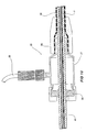
- the haemostatic seal which remains external of a patient in use has a clamping collar 26 which clamps the external sleeve 30 to the haemostatic seal 27.
- the haemostatic seal 27 has a silicone seal ring 28 to seal against the thick walled tubing 41 to provide the haemostatic seal and a side tube 29 for the introduction of medical reagents between the thick walled tubing 41 and the external sleeve 30.
- the release wire actuation section of the external manipulation section has a body 36 into the end of which is mounted the thick walled tubing 41 and through which passes the thin walled tube 15.
- Both the proximal wire release mechanism 24 and the distal wire release mechanism 25 are mounted for slidable movement on the body 36. Their positioning is such that the proximal wire release mechanism 24 must be moved before the distal wire release mechanism 25 can be moved. This means that the distal end of the prosthesis cannot be released until the proximal end of the prosthesis has been released.
- Clamping screws 37 are provided on each of the proximal wire release mechanism 24 and distal wire release mechanism 25 to prevent inadvertent early release of either end of the prosthesis.
- a haemostatic seal 38 is provided so the respective release wire can extend out through the body 36 to the respective release mechanisms.
- FIG 12 there is a pin vice 39 mounted onto the other end of the body 36 from the thick walled tube 41.
- the pin vice 39 has a screw cap 46 which when screwed in clamps vice jaws 47 against the thin walled metal tube 15 so that the thin walled tube 15 can only move with the body 26 and hence the thin walled tube can only move with the thick walled tube 41. With the clamp tightened the entire assembly except the external sleeve 30 can be moved as one.
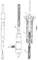
- FIG 2 to 7 show the various stages of the deployment of the prosthesis according to this embodiment of the invention.
- a guide wire (not shown) is introduced into the femoral artery and advanced until its tip is above the region into which the prosthesis is to be deployed.
- FIG 2 the introducer assembly is shown fully assembled ready for introduction into a patient.
- the prosthesis 20 is retained at each of its ends by the proximal and distal retaining assemblies respectively and compressed by the external sleeve 30. If it is an aortic aneurism which is to be grafted the introducer assembly can be inserted through a femoral artery over the guide wire in the form as shown in FIG 2 and positioned by radiographic techniques (not discussed here).
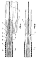
- FIG 3 it will be seen that once the introducer assembly is in a selected position the external sheath 30 is withdrawn to just proximal of the distal attachment device 40 so that the prosthesis 20 is now released so that it can expand radially except where the most proximal zigzag stent 21 is still retained within the proximal attachment device 10 and where its distal end 42 is retained within the external sheath 30.
- the prosthesis 20 may now be lengthened or shortened or rotated or compressed to accurately place in the desired place within the body lumen.
- X-ray opaque markers may be placed at known places along the prosthesis to assist with placement of the prosthesis.
- the proximal trigger wire 22 ( FIG 3 ) has been withdrawn by distal movement of the proximal wire release mechanism 24 ( FIG 3 ).
- the proximal wire release mechanism 24 and the proximal trigger wire 22 have be removed completely by passing the proximal wire release mechanism 24 over the pin vice 39,46 and the connection means 16 for a syringe.
- the screw cap 46 of the pin vice 39 has then been loosened so that the thin walled tubing 15 can been pushed in a proximal direction to move the proximal attachment means 10 in a proximal direction thereby releasing the zigzag stent 21 at the proximal end of the prosthesis from the proximal attachment means 10.
- the hooks or barbs 26 on the zigzag stent 21 grip into the walls of the lumen to hold the prosthesis therein. From this stage the proximal end of the prosthesis cannot be moved again.
- the distal end of the prosthesis 42 is still retained by the distal attachment means 40 with the loop 43 retained therein.
- the external sheath 30 has been withdrawn to distal of the distal attachment device 40 to allow the distal end of the attachment device to expand.
- the distal end of the prosthesis can still be moved so that the prosthesis can be rotated or lengthened or shortened or otherwise moved to accurately position the prosthesis.
- the prosthesis to be deployed is a bifurcated graft the movement at this stage can ensure that the shorter leg is directed in the direction of the contra-iliac artery
- the distal end 42 of the prosthesis has been released by removal of the distal trigger wire 44.
- the distal wire release mechanism 25 and the distal trigger wire 44 can be removed completely by passing the distal wire release mechanism 25 over the pin vice and the connection means 16 for a syringe.
- the loop 43 of the terminal distal zigzag stent is hence freed and the prosthesis is now free to expand to the walls of the vessel and the introducer is ready to be removed.
- the first stage of removal is shown in FIG 6 where the distal attachment device 40 is advanced to be received in the rear of the proximal attachment device 10 and then the proximal attachment device 10 including the tapered flexible extension 11 and the distal attachment device 40 are removed together as shown in FIG 7 .
- the external sleeve 30 has been advanced to cover the join between the proximal attachment device 10 and the distal attachment device 40 and is also removed with the proximal attachment device 10, the tapered flexible extension 11 and the distal attachment device 40 although these could be removed separately and then the external sleeve 30 removed later. This may have some advantage if further surgical procedures are necessary as a clear way is provided to advance other surgical equipment.
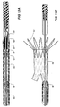
- FIGS 13A to FIG 13C shows the use of the introducer according to this invention with a self expanding bifurcated prosthesis
- FIGS 13A to FIG 13C the section of the introducer including the proximal attachment device and the distal attachment device of the introducer with a bifurcated prosthesis is shown.
- the bifurcated prosthesis 50 is retained within the external sheath 51 between the proximal attachment device 52 and the distal attachment device 53 with respective fixings to the proximal attachment device 52 and the distal attachment device 53 of the same for as shown in Figs 1 to 12 .
- the proximally extending zigzag stent 57 is retained within the proximal attachment device 52.
- an extension piece 59 can be inserted into the side arm 60 by a separate introducer from the other femoral artery as shown in Fig 13C .
- the release of the distal attachment device and the withdrawal of the introducer can the proceed in the same manner as discussed with respect to Figs 1 to 12 .
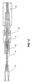
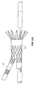
- FIG 14 An embodiment of introducer according to this invention suitable for the introduction of an extension prosthesis is shown in FIG 14 which shows the various portions of the introducer along its length.
- the embodiment includes a tapered flexible extension 70 mounted on a thin walled metal tube 71.
- the tapered flexible extension 70 includes a longitudinal aperture 73.
- the thin walled metal tube 71 is fastened to the tapered flexible extension and extends in a distal direction from the tapered flexible extension to external of the patient in use.
- the thin walled metal tube 71 extends to a connector 74 for the introduction of medical reagents as necessary.
- the prosthesis 75 is retained between the distal end 80 of the flexible extension and the proximal end 78 of a thick walled flexible tube 77.
- a sheath 79 is a sliding fit on the thick walled tube 77 and during the insertion process is fitted over the extension prosthesis up to the distal end 80 of the flexible extension 70 to provide a smooth surface for the progression of the introducer through the vascalature.
- the method of introduction of the extension prosthesis is as follows.
- a guide wire (not shown) is introduced into the femoral artery and advanced until its tip is above the region into which the prosthesis is to be deployed.
- the introducer is then advanced over the guide wire with a oscillating rotating action until the extension prosthesis is overlapped one full stent within the shorter leg of the prosthesis.
- a final position check may than be made before the sheath 79 is withdrawn while holding the thick walled tube 77 in place.
- the introducer can then be removed by withdrawing the flexible extension 70 to the thick walled tube 77 and covering the gap between then with the sheath 79.
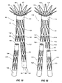
- FIG 15 shows an embodiment of a bifurcated prosthesis with an extension prosthesis according to this invention.
- the bifurcated prosthesis 90 has a generally inverted Y- shaped configuration having a body portion 91, a shorter leg 92 and a longer leg 93.
- the body of the prosthesis is constructed from a tubular woven synthetic material such as dacron.
- a first zigzag stent 95 which extends beyond the end of the prosthesis and has distally extending barbs 96.
- the prosthesis has a number of zigzag stents mounted to it and extending along its length.
- the stent 97 nearest the proximal end 94 is inside the tubular material so that the outside presents a smooth surface which in use engages against the inner wall of the vessel into which it is deployed to provide a barrier to the flow of blood.
- the stent 98 nearest the distal end 99 of the longer leg is also inside the tubular material so that the outside presents a smooth surface which in use engages against the inner wall of the vessel into which it is deployed to provide a barrier to the flow of blood.
- the rest of the stents 100 are arranged on the outside of the tubular material so that they present minimal restriction to the flow of blood through the prosthesis and present minimal sites for the growth of thromboses within the prosthesis.
- Each stent is sewn to the tubular material as shown particularly at 101.
- the longer leg 93 has one loop 43 of the terminal internal stent 98 extending beyond the end of the tubular material to act as the distal attachment means.
- the prosthesis according to this embodiment of the invention is adapted for fitting into aorta such that the end 94 is just distal of the renal arteries and the first zigzag stent 95 extend up to or over the renal arteries.
- the longer leg 93 extends down one of the iliac arteries and the shorter leg terminates in the aorta just short of the other iliac artery.
- the terminal stent 102 nearest the distal end 92 of the shorter leg is outside the tubular material so that the inside presents a smooth surface which in use engages against the outside of one end of an extension prosthesis.
- An extension prosthesis 104 is adapted for fitting into the shorter leg by the method as discussed above.
- the extension prosthesis 104 is constructed from a tubular synthetic material such as dacron and has terminal internal stents 105 and a plurality of external intermediate stents 106.
- FIG 16 shows an embodiment of a bifurcated prosthesis with two extension prostheses according to this invention.
- the bifurcated prosthesis 110 has a generally inverted Y- shaped configuration having a body portion 111, a shorter leg 112 and a longer leg 113.
- the body of the prosthesis is constructed from a tubular woven synthetic material such as dacron.
- a first zigzag stent 115 which extends beyond the end of the prosthesis and has distally extending barbs 116.
- the prosthesis has a number of zigzag stents mounted to it and extending along its length.
- the stent 117 nearest the proximal end 114 is inside the tubular material so that the outside presents a smooth surface which in use engages against the inner wall of the vessel into which it is deployed to provide a barrier to the flow of blood.
- the terminal stents 118 nearest the distal end 99 of the both the shorter and longer legs are outside the tubular material so that the inside presents a smooth surface which in use engages against the outside of one end of an extension prosthesis. Between these terminal stents the rest of the stents 119 are arranged on the outside of the tubular material so that they present minimal restriction to the flow of blood through the prosthesis and present minimal sites for the growth of thromboses within the prosthesis.
- the longer leg 113 has one loop 43 of the terminal external stent 118 extending beyond the end of the tubular material to act as the distal attachment means.
- Extension prostheses 120 and 121 are adapted for fitting into both the shorter and longer legs by the method as discussed above.
- Each of the extension prostheses 120 and 121 are constructed from a tubular synthetic material such as dacron and have terminal internal stents 122 and a plurality of external intermediate stents 123.
- the prosthesis according to this embodiment of the invention is adapted for fitting into aorta such that the end 114 is just distal of the renal arteries and the first zigzag stent 115 extend up to or over the renal arteries. As it is constructed from thin wire it does not obstruct the renal arteries if it extends over them.
- the longer leg 113 extends down one of the iliac arteries and the shorter leg terminates in the aorta just short of the other iliac artery.
- the extension prostheses when deployed extend down each iliac artery.
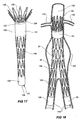
- FIG 17 shows an embodiment of a prosthesis according to this invention intended for aortouni-iliac deployment.
- the prosthesis 130 has a generally tapering tubular configuration having a body portion 131 extending down to a single leg 132 of lesser diameter than the body portion.
- the body of the prosthesis is constructed from a tubular woven synthetic material such as dacron.
- a first zigzag stent 135 which extends beyond the end of the prosthesis and has distally extending barbs 136.
- the prosthesis has a number of zigzag stents mounted to it and extending along its length.
- the stent 137 nearest the proximal end 134 is inside the tubular material so that the outside presents a smooth surface which in use engages against the inner wall of the vessel into which it is deployed to provide a barrier to the flow of blood.
- the stent 138 nearest the distal end 132 of the leg is also inside the tubular material so that the outside presents a smooth surface which in use engages against the inner wall of the vessel into which it is deployed to provide a barrier to the flow of blood.
- the rest of the stents 140 are arranged on the outside of the tubular material so that they present minimal restriction to the flow of blood through the prosthesis and present minimal sites for the growth of thromboses within the prosthesis.
- the leg 132 has one loop 43 of the terminal external stent 138 extending beyond the end of the tubular material to act as the distal attachment means.
- the prosthesis according to this embodiment of the invention is adapted for fitting into aorta such that the end 134 is just distal of the renal arteries and the first zigzag stent 135 extends up to or over the renal arteries.
- the leg 132 extends down one of the iliac arteries.
- the other iliac artery is intended to be closed of with a plug inserted via the femoral artery and a cross graft is surgically inserted between the iliac arteries to provide blood flow to both iliac arteries.
- FIG 18 shoes a deployed prosthesis according to the embodiment this invention within an aorta with an aneurism.
- the aneurism 150 is a ballooning of the aorta 152 between the renal arteries 153 and the iliac arteries 154.
- the prosthesis as shown in FIG 15 is deployed into the aorta so that it spans the aneurism allows blood flow from the aorta to the two iliac arteries.
- the proximal portion 94 of the prosthesis 90 which has the stent on the inside bears against the wall of the aorta 152 above the aneurism so that a good seal is obtained.
- the zigzag stent 95 which extends beyond the portion 94 extends over the entrances to the renal arteries but as the wire of the stent is fine occlusion does not occur.
- the distal end of the prosthesis 99 seals against the wall of one of the iliac arteries and the distal end 155 of the extension prosthesis 104 bears against the wall of the other iliac artery.
- the join 156 between the prosthesis 90 and the extension prosthesis 104 seals because there is a smooth connection between the smooth inner surface on the shorter leg 112 and the smooth outer surface of the proximal end of the extension prosthesis 104.
- the size of the prostheses according to this invention may be selected so that there is in effect an interference fit in the sound parts of the vessels to give good sealing onto the inner walls of the vessels.
- the prosthesis at its widest may range in diameter from 20 mm to 32 mm where it fits into the aorta and from 8 mm to 24 mm where it fits into the iliac arteries.
- the embodiment shown in FIG 15 may have an overall length of from 120 mm to 180 mm not counting the length of the uncovered proximal stent and the extension prosthesis may have a length of from 35 mm to 125 mm and a diameter of from 8 mm to 24 mm.
- the amount of overlap between the shorter leg of the prosthesis and the proximal end of the extension prosthesis is from 15 mm to 21 mm.
- the embodiment shown in FIG 16 may have an overall length of from 100 mm to 130 mm not counting the length of the uncovered proximal stent.
- the difference in length between the shorter and longer legs of the bifurcated prosthesis may be 30 mm.
- the shorter extension prosthesis may have a length of from 65 mm to 125 mm and a diameter of from 8 mm to 24 mm.
- the amount of overlap between the shorter leg of the prosthesis and the proximal end of the longer extension prosthesis is from 15 mm to 22 mm.
- the longer extension prosthesis may have a length of from 35 mm to 125 mm and a diameter of from 8 mm to 24 mm.
- the amount of overlap between the longer leg of the prosthesis and the proximal end of the shorter extension prosthesis is from 15 mm to 22 mm.
- the embodiment shown in FIG 17 may have an overall length of from 90 mm to 180 mm not counting the length of the uncovered proximal stent.
- the prosthesis at its widest may range in diameter from 20 mm to 32 mm where it fits into the aorta and from 8 mm to 24 mm where it fits into one of the iliac arteries.
Landscapes
- Health & Medical Sciences (AREA)
- Engineering & Computer Science (AREA)
- Biomedical Technology (AREA)
- Heart & Thoracic Surgery (AREA)
- Public Health (AREA)
- Transplantation (AREA)
- Cardiology (AREA)
- Veterinary Medicine (AREA)
- Oral & Maxillofacial Surgery (AREA)
- Vascular Medicine (AREA)
- Life Sciences & Earth Sciences (AREA)
- Animal Behavior & Ethology (AREA)
- General Health & Medical Sciences (AREA)
- Gastroenterology & Hepatology (AREA)
- Pulmonology (AREA)
- Prostheses (AREA)
- Media Introduction/Drainage Providing Device (AREA)
- Graft Or Block Polymers (AREA)
Applications Claiming Priority (3)
| Application Number | Priority Date | Filing Date | Title |
|---|---|---|---|
| AUPO7008A AUPO700897A0 (en) | 1997-05-26 | 1997-05-26 | A method and means of deploying a graft |
| AUPO700897 | 1997-05-26 | ||
| PCT/AU1998/000383 WO1998053761A1 (en) | 1997-05-26 | 1998-05-25 | A prosthesis and a method and means of deploying a prosthesis |
Publications (3)
| Publication Number | Publication Date |
|---|---|
| EP1014888A1 EP1014888A1 (en) | 2000-07-05 |
| EP1014888A4 EP1014888A4 (en) | 2003-03-19 |
| EP1014888B1 true EP1014888B1 (en) | 2008-10-01 |
Family
ID=3801299
Family Applications (1)
| Application Number | Title | Priority Date | Filing Date |
|---|---|---|---|
| EP98922515A Expired - Lifetime EP1014888B1 (en) | 1997-05-26 | 1998-05-25 | Means of deploying a prosthesis |
Country Status (10)
| Country | Link |
|---|---|
| US (1) | US7435253B1 (enExample) |
| EP (1) | EP1014888B1 (enExample) |
| JP (3) | JP4368428B2 (enExample) |
| AT (1) | ATE409444T1 (enExample) |
| AU (2) | AUPO700897A0 (enExample) |
| CA (1) | CA2283782C (enExample) |
| DE (1) | DE69840072D1 (enExample) |
| DK (1) | DK1014888T3 (enExample) |
| ES (1) | ES2316164T3 (enExample) |
| WO (1) | WO1998053761A1 (enExample) |
Cited By (1)
| Publication number | Priority date | Publication date | Assignee | Title |
|---|---|---|---|---|
| EP3989873A1 (de) * | 2019-06-28 | 2022-05-04 | Protembis GmbH | Embolieschutzvorrichtung zur zuführung in einen aortenbogen |
Families Citing this family (296)
| Publication number | Priority date | Publication date | Assignee | Title |
|---|---|---|---|---|
| AUPP083597A0 (en) * | 1997-12-10 | 1998-01-08 | William A Cook Australia Pty Ltd | Endoluminal aortic stents |
| US6960217B2 (en) | 2001-11-28 | 2005-11-01 | Aptus Endosystems, Inc. | Endovascular aneurysm repair system |
| US7491232B2 (en) | 1998-09-18 | 2009-02-17 | Aptus Endosystems, Inc. | Catheter-based fastener implantation apparatus and methods with implantation force resolution |
| US6887268B2 (en) | 1998-03-30 | 2005-05-03 | Cordis Corporation | Extension prosthesis for an arterial repair |
| US6656215B1 (en) | 2000-11-16 | 2003-12-02 | Cordis Corporation | Stent graft having an improved means for attaching a stent to a graft |
| US6858034B1 (en) | 1999-05-20 | 2005-02-22 | Scimed Life Systems, Inc. | Stent delivery system for prevention of kinking, and method of loading and using same |
| US6607551B1 (en) | 1999-05-20 | 2003-08-19 | Scimed Life Systems, Inc. | Stent delivery system with nested stabilizer |
| US6398802B1 (en) | 1999-06-21 | 2002-06-04 | Scimed Life Systems, Inc. | Low profile delivery system for stent and graft deployment |
| EP1113764B1 (en) * | 1999-07-16 | 2003-11-05 | Med Institute, Inc. | Stent adapted for tangle-free deployment |
| US6610087B1 (en) * | 1999-11-16 | 2003-08-26 | Scimed Life Systems, Inc. | Endoluminal stent having a matched stiffness region and/or a stiffness gradient and methods for providing stent kink resistance |
| US6280466B1 (en) * | 1999-12-03 | 2001-08-28 | Teramed Inc. | Endovascular graft system |
| US6296661B1 (en) | 2000-02-01 | 2001-10-02 | Luis A. Davila | Self-expanding stent-graft |
| US6245100B1 (en) | 2000-02-01 | 2001-06-12 | Cordis Corporation | Method for making a self-expanding stent-graft |
| AU769900B2 (en) | 2000-03-03 | 2004-02-05 | Cook Medical Technologies Llc | Endovascular device having a stent |
| DE60139460D1 (de) * | 2000-03-14 | 2009-09-17 | Cook Inc | Endovaskulärer stent-graft |
| JP4726382B2 (ja) | 2000-05-04 | 2011-07-20 | オレゴン ヘルス サイエンシーズ ユニバーシティー | ステント移植片 |
| US6843802B1 (en) | 2000-11-16 | 2005-01-18 | Cordis Corporation | Delivery apparatus for a self expanding retractable stent |
| US6942692B2 (en) | 2000-11-16 | 2005-09-13 | Cordis Corporation | Supra-renal prosthesis and renal artery bypass |
| US7267685B2 (en) | 2000-11-16 | 2007-09-11 | Cordis Corporation | Bilateral extension prosthesis and method of delivery |
| US7229472B2 (en) | 2000-11-16 | 2007-06-12 | Cordis Corporation | Thoracic aneurysm repair prosthesis and system |
| KR20030094304A (ko) | 2001-03-28 | 2003-12-11 | 쿡 인코포레이티드 | 모듈식 스텐트 그라프트 조립체 및 그 사용 방법 |
| US8231639B2 (en) | 2001-11-28 | 2012-07-31 | Aptus Endosystems, Inc. | Systems and methods for attaching a prosthesis within a body lumen or hollow organ |
| US9320503B2 (en) | 2001-11-28 | 2016-04-26 | Medtronic Vascular, Inc. | Devices, system, and methods for guiding an operative tool into an interior body region |
| US7147657B2 (en) * | 2003-10-23 | 2006-12-12 | Aptus Endosystems, Inc. | Prosthesis delivery systems and methods |
| US20050177180A1 (en) | 2001-11-28 | 2005-08-11 | Aptus Endosystems, Inc. | Devices, systems, and methods for supporting tissue and/or structures within a hollow body organ |
| US20070073389A1 (en) | 2001-11-28 | 2007-03-29 | Aptus Endosystems, Inc. | Endovascular aneurysm devices, systems, and methods |
| US20100016943A1 (en) | 2001-12-20 | 2010-01-21 | Trivascular2, Inc. | Method of delivering advanced endovascular graft |
| US7147661B2 (en) | 2001-12-20 | 2006-12-12 | Boston Scientific Santa Rosa Corp. | Radially expandable stent |
| US7326237B2 (en) | 2002-01-08 | 2008-02-05 | Cordis Corporation | Supra-renal anchoring prosthesis |
| US8221482B2 (en) | 2002-01-28 | 2012-07-17 | Orbusneich Medical, Inc. | Flared ostial endoprosthesis and delivery system |
| US7235095B2 (en) | 2002-02-22 | 2007-06-26 | Scimed Life Systems, Inc. | Method and system for deploying multi-part endoluminal devices |
| US7887573B2 (en) | 2002-02-22 | 2011-02-15 | Boston Scientific Scimed, Inc. | Method and apparatus for deployment of an endoluminal device |
| US7004964B2 (en) | 2002-02-22 | 2006-02-28 | Scimed Life Systems, Inc. | Apparatus and method for deployment of an endoluminal device |
| US7828839B2 (en) | 2002-05-16 | 2010-11-09 | Cook Incorporated | Flexible barb for anchoring a prosthesis |
| ATE310559T1 (de) * | 2002-05-29 | 2005-12-15 | Cook William A Australia | Trigger-draht system für eine prothesenplazierungsvorrichtung |
| US20030225446A1 (en) * | 2002-05-29 | 2003-12-04 | William A. Cook Australia Pty Ltd. | Multi-piece prosthesis deployment apparatus |
| US7264632B2 (en) * | 2002-06-07 | 2007-09-04 | Medtronic Vascular, Inc. | Controlled deployment delivery system |
| JP4353481B2 (ja) | 2002-06-26 | 2009-10-28 | クック インコーポレイティド | ステントグラフト固定装置 |
| CA2489495C (en) * | 2002-06-28 | 2010-07-13 | Cook Incorporated | Thoracic aortic aneurysm stent graft |
| ATE533436T1 (de) * | 2002-06-28 | 2011-12-15 | Cook Medical Technologies Llc | Brust-einführvorrichtung |
| US11890181B2 (en) | 2002-07-22 | 2024-02-06 | Tmt Systems, Inc. | Percutaneous endovascular apparatus for repair of aneurysms and arterial blockages |
| US7722657B2 (en) | 2002-08-23 | 2010-05-25 | William A. Cook Australia Pty. Ltd. | Asymmetric stent graft attachment |
| EP1545396B1 (en) | 2002-08-23 | 2008-12-17 | William A. Cook Australia Pty. Ltd. | Composite prosthesis |
| AU2002951147A0 (en) * | 2002-09-02 | 2002-09-19 | Cook Incorporated | Branch grafting device and method |
| US8518096B2 (en) | 2002-09-03 | 2013-08-27 | Lifeshield Sciences Llc | Elephant trunk thoracic endograft and delivery system |
| US20040116997A1 (en) | 2002-09-20 | 2004-06-17 | Taylor Charles S. | Stent-graft with positioning anchor |
| EP1567093B1 (en) | 2002-12-04 | 2009-01-21 | Cook Incorporated | Method and device for treating aortic dissection |
| US9125733B2 (en) | 2003-01-14 | 2015-09-08 | The Cleveland Clinic Foundation | Branched vessel endoluminal device |
| WO2004064686A1 (en) | 2003-01-14 | 2004-08-05 | The Cleveland Clinic Foundation | Branched vessel endoluminal device |
| US7611528B2 (en) * | 2003-01-24 | 2009-11-03 | Medtronic Vascular, Inc. | Stent-graft delivery system |
| EP1608293B1 (en) | 2003-04-03 | 2015-06-03 | Cook Medical Technologies LLC | Deployment system for a branched stent graft |
| GB0309616D0 (en) | 2003-04-28 | 2003-06-04 | Angiomed Gmbh & Co | Loading and delivery of self-expanding stents |
| US8784472B2 (en) * | 2003-08-15 | 2014-07-22 | Boston Scientific Scimed, Inc. | Clutch driven stent delivery system |
| US8500792B2 (en) | 2003-09-03 | 2013-08-06 | Bolton Medical, Inc. | Dual capture device for stent graft delivery system and method for capturing a stent graft |
| US11259945B2 (en) | 2003-09-03 | 2022-03-01 | Bolton Medical, Inc. | Dual capture device for stent graft delivery system and method for capturing a stent graft |
| US20080264102A1 (en) | 2004-02-23 | 2008-10-30 | Bolton Medical, Inc. | Sheath Capture Device for Stent Graft Delivery System and Method for Operating Same |
| US20070198078A1 (en) | 2003-09-03 | 2007-08-23 | Bolton Medical, Inc. | Delivery system and method for self-centering a Proximal end of a stent graft |
| US11596537B2 (en) | 2003-09-03 | 2023-03-07 | Bolton Medical, Inc. | Delivery system and method for self-centering a proximal end of a stent graft |
| US9198786B2 (en) | 2003-09-03 | 2015-12-01 | Bolton Medical, Inc. | Lumen repair device with capture structure |
| US7763063B2 (en) | 2003-09-03 | 2010-07-27 | Bolton Medical, Inc. | Self-aligning stent graft delivery system, kit, and method |
| US8292943B2 (en) | 2003-09-03 | 2012-10-23 | Bolton Medical, Inc. | Stent graft with longitudinal support member |
| US7699865B2 (en) * | 2003-09-12 | 2010-04-20 | Rubicon Medical, Inc. | Actuating constraining mechanism |
| US7651519B2 (en) | 2003-09-16 | 2010-01-26 | Cook Incorporated | Prosthesis deployment system |
| US8043357B2 (en) | 2003-10-10 | 2011-10-25 | Cook Medical Technologies Llc | Ring stent |
| US8734501B2 (en) | 2003-10-10 | 2014-05-27 | Cook Medical Technologies Llc | Composite stent graft |
| DE602004013352T2 (de) | 2003-10-10 | 2009-05-07 | Cook Inc., Bloomington | Stentimplantate mit fenstern |
| WO2005034811A1 (en) * | 2003-10-10 | 2005-04-21 | William Cook Europe Aps | Stent graft retention system |
| US8012193B2 (en) | 2003-10-14 | 2011-09-06 | William A. Cook Australia Pty, Ltd | Introducer for an iliac side branch device |
| US7998186B2 (en) | 2003-10-14 | 2011-08-16 | William A. Cook Australia Pty. Ltd. | Introducer for a side branch device |
| EP1673041B1 (en) | 2003-10-15 | 2010-04-21 | Cook Incorporated | Prosthesis deployment system retention device |
| AU2011203524B2 (en) * | 2003-10-23 | 2012-08-30 | Aptus Endosystems, Inc. | Prosthesis delivery systems and methods |
| US9078780B2 (en) | 2003-11-08 | 2015-07-14 | Cook Medical Technologies Llc | Balloon flareable branch vessel prosthesis and method |
| ATE478629T1 (de) | 2003-12-17 | 2010-09-15 | Cook Inc | Verbundene beinverlängerungen für eine endoluminal-prothese |
| US7651521B2 (en) * | 2004-03-02 | 2010-01-26 | Cardiomind, Inc. | Corewire actuated delivery system with fixed distal stent-carrying extension |
| US7674284B2 (en) | 2004-03-31 | 2010-03-09 | Cook Incorporated | Endoluminal graft |
| US8048140B2 (en) | 2004-03-31 | 2011-11-01 | Cook Medical Technologies Llc | Fenestrated intraluminal stent system |
| US9498322B2 (en) | 2004-03-31 | 2016-11-22 | Cook Medical Technologies Llc | Multi-portion endoluminal prosthesis |
| ATE464855T1 (de) | 2004-03-31 | 2010-05-15 | Cook Inc | Transplantatmaterial und gefässprothese mit extrazellulärer kollagenmatrix und dessen herstellungsverfahren |
| EP1729684B1 (en) | 2004-03-31 | 2010-12-15 | Cook Incorporated | Stent deployment device |
| US8465536B2 (en) | 2004-04-06 | 2013-06-18 | Cook Medical Technologies Llc | Prosthesis deployment system |
| AU2005254104B2 (en) | 2004-06-15 | 2010-08-26 | Cook Incorporated | Stent graft with internal tube |
| EP1765221A1 (en) | 2004-06-16 | 2007-03-28 | Cook Incorporated | Thoracic deployment device and stent graft |
| US8048145B2 (en) | 2004-07-22 | 2011-11-01 | Endologix, Inc. | Graft systems having filling structures supported by scaffolds and methods for their use |
| JP2008518710A (ja) * | 2004-11-03 | 2008-06-05 | セガン,ジャック | 血管移植片および展開システム |
| US8864819B2 (en) | 2004-12-17 | 2014-10-21 | Cook Medical Technologies Llc | Stented side branch graft |
| DE102005003632A1 (de) | 2005-01-20 | 2006-08-17 | Fraunhofer-Gesellschaft zur Förderung der angewandten Forschung e.V. | Katheter für die transvaskuläre Implantation von Herzklappenprothesen |
| US20060224232A1 (en) * | 2005-04-01 | 2006-10-05 | Trivascular, Inc. | Hybrid modular endovascular graft |
| WO2006113501A1 (en) | 2005-04-13 | 2006-10-26 | The Cleveland Clinic Foundation | Endoluminal prosthesis |
| AU2006269419A1 (en) | 2005-07-07 | 2007-01-18 | Nellix, Inc. | Systems and methods for endovascular aneurysm treatment |
| DE102006020687A1 (de) | 2005-07-19 | 2007-02-08 | Aesculap Ag & Co. Kg | Stentgraft-Prothese |
| WO2007014088A2 (en) | 2005-07-25 | 2007-02-01 | Cook Incorporated | Intraluminal prosthesis and stent |
| AU2006280948B2 (en) | 2005-08-18 | 2011-10-27 | Cook Incorporated | Assembly of stent grafts |
| US7670369B2 (en) | 2005-10-13 | 2010-03-02 | Cook Incorporated | Endoluminal prosthesis |
| CN101466316B (zh) | 2005-10-20 | 2012-06-27 | 阿普特斯内系统公司 | 包括使用固定件工具的用于修复物递送和植入的装置、系统和方法 |
| WO2007053592A2 (en) | 2005-10-31 | 2007-05-10 | Cook Incorporated | Composite stent graft |
| US8709060B2 (en) | 2005-12-23 | 2014-04-29 | Cook Medical Technologies Llc | Prosthesis deployment system |
| US8728144B2 (en) | 2005-12-29 | 2014-05-20 | Cook Medical Technologies Llc | Endoluminal device including a mechanism for proximal or distal fixation, and sealing and methods of use thereof |
| US8518098B2 (en) * | 2006-02-21 | 2013-08-27 | Cook Medical Technologies Llc | Split sheath deployment system |
| US9308105B2 (en) | 2006-04-19 | 2016-04-12 | Cook Medical Technologies Llc | Delivery device for an endoluminal prosthesis |
| AU2007240703C1 (en) | 2006-04-19 | 2012-06-14 | Cleveland Clinic Foundation | Twin bifurcated stent graft |
| EP2015706B1 (en) | 2006-04-27 | 2016-08-03 | Cook Medical Technologies LLC | Deploying medical implants |
| EP2029062B1 (en) * | 2006-06-02 | 2012-05-30 | William A. Cook Australia Pty. Ltd. | Multi-port delivery device |
| CA2653190C (en) | 2006-06-06 | 2015-07-14 | Cook Incorporated | Stent with a crush-resistant zone |
| US8118853B2 (en) | 2006-06-19 | 2012-02-21 | Cook Medical Technologies Llc | Prosthesis delivery and deployment device |
| US8021412B2 (en) | 2006-08-18 | 2011-09-20 | William A. Cook Australia Pty. Ltd. | Iliac extension with flared cuff |
| EP2088964A1 (en) | 2006-11-07 | 2009-08-19 | William A. Cook Australia Pty. Ltd. | Stent graft for treatment of an emergency rupture of a vessel |
| EP2088969B1 (en) | 2006-11-30 | 2014-08-20 | Cook Medical Technologies LLC | Implant release mechanism |
| US8070799B2 (en) | 2006-12-19 | 2011-12-06 | Sorin Biomedica Cardio S.R.L. | Instrument and method for in situ deployment of cardiac valve prostheses |
| US7896915B2 (en) | 2007-04-13 | 2011-03-01 | Jenavalve Technology, Inc. | Medical device for treating a heart valve insufficiency |
| US9295551B2 (en) * | 2007-04-13 | 2016-03-29 | Jenavalve Technology Gmbh | Methods of implanting an endoprosthesis |
| US8007470B2 (en) * | 2007-07-10 | 2011-08-30 | Cook Medical Technologies Llc | Minimally invasive medical device and method for delivery of therapeutic or diagnostic agents into a vessel wall |
| US9119742B2 (en) | 2007-07-16 | 2015-09-01 | Cook Medical Technologies Llc | Prosthesis delivery and deployment device |
| US9149379B2 (en) | 2007-07-16 | 2015-10-06 | Cook Medical Technologies Llc | Delivery device |
| US8092510B2 (en) * | 2007-07-25 | 2012-01-10 | Cook Medical Technologies Llc | Retention wire for self-expanding stent |
| JP5364933B2 (ja) * | 2007-08-13 | 2013-12-11 | クック・メディカル・テクノロジーズ・リミテッド・ライアビリティ・カンパニー | 配置装置 |
| US8808367B2 (en) | 2007-09-07 | 2014-08-19 | Sorin Group Italia S.R.L. | Prosthetic valve delivery system including retrograde/antegrade approach |
| US8663309B2 (en) | 2007-09-26 | 2014-03-04 | Trivascular, Inc. | Asymmetric stent apparatus and method |
| US9474641B2 (en) | 2007-10-23 | 2016-10-25 | Cook Medical Technologies Llc | Indwelling catheter arrangement |
| US7828840B2 (en) | 2007-11-15 | 2010-11-09 | Med Institute, Inc. | Medical devices and methods for local delivery of angiotensin II type 2 receptor antagonists |
| US8858608B2 (en) | 2007-12-10 | 2014-10-14 | Cook Medical Technologies Llc | Lubrication apparatus for a delivery and deployment device |
| WO2009082654A1 (en) | 2007-12-21 | 2009-07-02 | Cleveland Clinic Foundation | Prosthesis for implantation in aorta |
| US7566342B2 (en) * | 2007-12-27 | 2009-07-28 | Cook Incorporated | Delivery system for medical device |
| WO2009105699A1 (en) | 2008-02-22 | 2009-08-27 | Endologix, Inc. | Design and method of placement of a graft or graft system |
| US9044318B2 (en) | 2008-02-26 | 2015-06-02 | Jenavalve Technology Gmbh | Stent for the positioning and anchoring of a valvular prosthesis |
| ES2903231T3 (es) | 2008-02-26 | 2022-03-31 | Jenavalve Tech Inc | Stent para el posicionamiento y anclaje de una prótesis valvular en un sitio de implantación en el corazón de un paciente |
| WO2009146128A1 (en) * | 2008-04-03 | 2009-12-03 | William Cook Europe Aps | Implant release mechanism |
| US8236040B2 (en) | 2008-04-11 | 2012-08-07 | Endologix, Inc. | Bifurcated graft deployment systems and methods |
| EP2278939B1 (en) | 2008-04-25 | 2021-04-14 | Endologix LLC | Stent graft delivery system |
| AU2009256084A1 (en) | 2008-06-04 | 2009-12-10 | Nellix, Inc. | Sealing apparatus and methods of use |
| ES2749741T3 (es) | 2008-06-30 | 2020-03-23 | Bolton Medical Inc | Sistemas de aneurismas aórticos abdominales |
| JP5134729B2 (ja) | 2008-07-01 | 2013-01-30 | エンドロジックス、インク | カテーテルシステム |
| CA2740867C (en) | 2008-10-16 | 2018-06-12 | Aptus Endosystems, Inc. | Devices, systems, and methods for endovascular staple and/or prosthesis delivery and implantation |
| WO2010078352A1 (en) | 2008-12-30 | 2010-07-08 | Wilson-Cook Medical Inc. | Delivery device |
| GB0901496D0 (en) | 2009-01-29 | 2009-03-11 | Angiomed Ag | Delivery device for delivering a stent device |
| EP3284447B1 (en) | 2009-03-13 | 2020-05-20 | Bolton Medical Inc. | System for deploying an endoluminal prosthesis at a surgical site |
| WO2010127040A1 (en) | 2009-04-28 | 2010-11-04 | Endologix, Inc. | Apparatus and method of placement of a graft or graft system |
| US10772717B2 (en) | 2009-05-01 | 2020-09-15 | Endologix, Inc. | Percutaneous method and device to treat dissections |
| US9579103B2 (en) | 2009-05-01 | 2017-02-28 | Endologix, Inc. | Percutaneous method and device to treat dissections |
| EP2250970B1 (en) | 2009-05-13 | 2012-12-26 | Sorin Biomedica Cardio S.r.l. | Device for surgical interventions |
| US8858613B2 (en) | 2010-09-20 | 2014-10-14 | Altura Medical, Inc. | Stent graft delivery systems and associated methods |
| GB0909319D0 (en) | 2009-05-29 | 2009-07-15 | Angiomed Ag | Transluminal delivery system |
| US8491646B2 (en) | 2009-07-15 | 2013-07-23 | Endologix, Inc. | Stent graft |
| WO2011017123A2 (en) | 2009-07-27 | 2011-02-10 | Endologix, Inc. | Stent graft |
| AU2010306961B2 (en) | 2009-10-13 | 2013-10-10 | Cook Medical Technologies Llc | Paraplegia prevention stent graft |
| US9095456B2 (en) | 2009-10-13 | 2015-08-04 | Cook Medical Technologies Llc | Paraplegia prevention stent graft |
| WO2011059707A1 (en) | 2009-10-29 | 2011-05-19 | William A. Cook Australia Pty. Ltd. | Stent delivery system with nitinol trigger wire |
| CN201578402U (zh) * | 2009-11-16 | 2010-09-15 | 南京微创医学科技有限公司 | 能精确定位的支架置入器 |
| ES2577853T3 (es) | 2009-12-01 | 2016-07-19 | Altura Medical, Inc. | Dispositivos de endoinjerto modular |
| US20110276078A1 (en) | 2009-12-30 | 2011-11-10 | Nellix, Inc. | Filling structure for a graft system and methods of use |
| WO2011094527A1 (en) | 2010-01-29 | 2011-08-04 | Cook Medical Technologies Llc | Mechanically expandable delivery and dilation systems |
| US8663305B2 (en) | 2010-04-20 | 2014-03-04 | Medtronic Vascular, Inc. | Retraction mechanism and method for graft cover retraction |
| US8747448B2 (en) | 2010-04-30 | 2014-06-10 | Medtronic Vascular, Inc. | Stent graft delivery system |
| US8623064B2 (en) | 2010-04-30 | 2014-01-07 | Medtronic Vascular, Inc. | Stent graft delivery system and method of use |
| US10856978B2 (en) | 2010-05-20 | 2020-12-08 | Jenavalve Technology, Inc. | Catheter system |
| CA2799459A1 (en) | 2010-05-25 | 2011-12-01 | Jenavalve Technology Inc. | Prosthetic heart valve and transcatheter delivered endoprosthesis comprising a prosthetic heart valve and a stent |
| AU2010202487B1 (en) | 2010-06-15 | 2011-07-28 | Cook Incorporated | Pre-loaded multiport delivery device |
| US8419783B2 (en) | 2010-07-07 | 2013-04-16 | Cook Medical Technologies Llc | Graft deployment assist tool |
| US9101455B2 (en) | 2010-08-13 | 2015-08-11 | Cook Medical Technologies Llc | Preloaded wire for endoluminal device |
| CA2747610C (en) | 2010-08-13 | 2014-09-16 | Cook Medical Technologies Llc | Precannulated fenestration |
| EP2635241B1 (en) | 2010-11-02 | 2019-02-20 | Endologix, Inc. | Apparatus for placement of a graft or graft system |
| WO2012068298A1 (en) | 2010-11-17 | 2012-05-24 | Endologix, Inc. | Devices and methods to treat vascular dissections |
| AU2010254599B1 (en) | 2010-12-15 | 2011-02-17 | Cook Incorporated | Hybrid Type A dissection device |
| US9155612B2 (en) | 2011-01-10 | 2015-10-13 | Intermountain Invention Management, Llc | Composite stent grafts for in situ assembly and related methods |
| US8801768B2 (en) | 2011-01-21 | 2014-08-12 | Endologix, Inc. | Graft systems having semi-permeable filling structures and methods for their use |
| AU2011200858B1 (en) | 2011-02-28 | 2012-04-05 | Cook Medical Technologies Llc | Stent graft with valve arrangement |
| CN105232195B (zh) | 2011-03-01 | 2018-06-08 | 恩朵罗杰克斯股份有限公司 | 递送导管系统 |
| US9440059B2 (en) | 2011-03-18 | 2016-09-13 | Cook Medical Technologies Llc | Adjustable diameter hemostatic valve |
| JP5976777B2 (ja) | 2011-04-06 | 2016-08-24 | エンドーロジックス インコーポレイテッド | 血管内動脈瘤治療のための方法およびシステム |
| EP2517671B1 (en) | 2011-04-28 | 2016-05-11 | Cook Medical Technologies LLC | Apparatus for facilitating deployment of an endoluminal prosthesis |
| US8945205B2 (en) | 2011-04-28 | 2015-02-03 | The Cleveland Clinic Foundation | Branch vessel prostheses |
| AU2011202175B1 (en) | 2011-05-11 | 2011-07-28 | Cook Medical Technologies Llc | Rotation operated delivery device |
| AU2011202174B1 (en) | 2011-05-11 | 2011-08-25 | Cook Medical Technologies Llc | Introducer with ratchet handle drive |
| US8551158B2 (en) | 2011-05-13 | 2013-10-08 | Cook Medical Technologies Llc | Steerable iliac branch device |
| US20120303048A1 (en) | 2011-05-24 | 2012-11-29 | Sorin Biomedica Cardio S.R.I. | Transapical valve replacement |
| EP2540338B1 (en) | 2011-06-03 | 2015-09-16 | Cook Medical Technologies LLC | Hemostatic valve with multi-layer valve structure |
| EP2535025A1 (en) | 2011-06-17 | 2012-12-19 | Cook Medical Technologies LLC | Trigger wire release mechanism |
| US10010412B2 (en) * | 2011-07-27 | 2018-07-03 | Edwards Lifesciences Corporation | Conical crimper |
| AU2012209013B2 (en) | 2011-08-02 | 2013-11-14 | Cook Medical Technologies Llc | Delivery device having a variable diameter introducer sheath |
| EP2564812B1 (en) | 2011-08-31 | 2018-12-19 | Cook Medical Technologies LLC | Delivery system for an endoluminal prosthesis |
| CA2852369A1 (en) | 2011-10-21 | 2013-04-25 | Jenavalve Technology Inc. | Catheter system for introducing an expandable heart valve stent into the body of a patient, insertion system with a catheter system and medical device for treatment of a heart valve defect |
| US8728148B2 (en) | 2011-11-09 | 2014-05-20 | Cook Medical Technologies Llc | Diameter reducing tie arrangement for endoluminal prosthesis |
| BR112014011353A2 (pt) | 2011-11-11 | 2017-06-06 | Bolton Medical Inc | enxertos endovasculares universais |
| WO2013074990A1 (en) | 2011-11-16 | 2013-05-23 | Bolton Medical, Inc. | Device and method for aortic branched vessel repair |
| US9220620B2 (en) | 2011-11-22 | 2015-12-29 | Cook Medical Technologies Llc | Endoluminal prosthesis introducer |
| EP2985007B1 (en) | 2011-12-22 | 2019-11-13 | Cook Medical Technologies LLC | Preloaded wire for endoluminal device |
| US8894701B2 (en) | 2011-12-23 | 2014-11-25 | Cook Medical Technologies Llc | Hybrid balloon-expandable/self-expanding prosthesis for deployment in a body vessel and method of making |
| DE102012100754A1 (de) * | 2012-01-31 | 2013-08-01 | Jotec Gmbh | Modularer Stentgraft |
| US9498363B2 (en) | 2012-04-06 | 2016-11-22 | Trivascular, Inc. | Delivery catheter for endovascular device |
| PT2836159T (pt) * | 2012-04-12 | 2018-11-07 | Sanford Health | Enxerto de stent de desramificação de grande vaso |
| US8702791B2 (en) | 2012-04-12 | 2014-04-22 | Sanford Health | Debranching visceral stent graft and methods for use |
| BR112014025430A2 (pt) | 2012-04-12 | 2020-03-10 | Bolton Medical, Inc. | Dispositivo de envio protético vascular e método de uso |
| US10357353B2 (en) | 2012-04-12 | 2019-07-23 | Sanford Health | Combination double-barreled and debranching stent grafts and methods for use |
| JP6227632B2 (ja) | 2012-05-16 | 2017-11-08 | イェーナヴァルヴ テクノロジー ゲゼルシャフト ミット ベシュレンクテル ハフツング | 拡張可能心臓代用弁を導入するためのカテーテル送達システムおよび心臓弁欠陥の治療のための医療デバイス |
| CA2818268C (en) | 2012-06-13 | 2016-07-19 | Cook Medical Technologies Llc | Systems and methods for deploying a portion of a stent using at least one coiled member |
| US9132025B2 (en) | 2012-06-15 | 2015-09-15 | Trivascular, Inc. | Bifurcated endovascular prosthesis having tethered contralateral leg |
| US10342699B2 (en) | 2012-08-03 | 2019-07-09 | J.D. Franco & Co., Llc | Systems and methods for treating eye diseases |
| CN105050549B (zh) | 2012-08-10 | 2017-07-21 | 阿尔图拉医疗公司 | 支架输送系统以及相关方法 |
| US9308107B2 (en) | 2012-08-27 | 2016-04-12 | Cook Medical Technologies Llc | Endoluminal prosthesis and delivery device |
| EP2712639B1 (en) | 2012-09-28 | 2015-06-24 | Gambro Lundia AB | An apparatus for extracorporeal blood treatment and a control method therefor |
| US20140121750A1 (en) | 2012-10-31 | 2014-05-01 | Cook Medical Technologies Llc | Fixation Process For Nesting Stents |
| AU2012258395B1 (en) | 2012-11-27 | 2013-03-28 | Cook Medical Technologies Llc | Assembly of stent grafts with diameter reducing ties |
| AU2012258394B1 (en) | 2012-11-27 | 2013-03-07 | Cook Medical Technologies Llc | Stent graft having a closeable fenestration |
| MX360302B (es) | 2012-12-14 | 2018-10-29 | Sanford Health | Combinacion de doble barril e injerto de estent desramificante y métodos para su uso. |
| EP2745813A1 (en) | 2012-12-18 | 2014-06-25 | Cook Medical Technologies LLC | Preloaded wire for endoluminal device |
| US9687373B2 (en) | 2012-12-21 | 2017-06-27 | Cook Medical Technologies Llc | Systems and methods for securing and releasing a portion of a stent |
| AU2013273849B2 (en) | 2012-12-26 | 2015-02-12 | Cleveland Clinic Foundation | Endoluminal prosthesis having modular branches and methods of deployment |
| US11331208B2 (en) * | 2013-03-05 | 2022-05-17 | Cook Medical Technologies Llc | Inner catheter with a pusher band |
| US9308108B2 (en) | 2013-03-13 | 2016-04-12 | Cook Medical Technologies Llc | Controlled release and recapture stent-deployment device |
| US9545324B2 (en) | 2013-03-13 | 2017-01-17 | Cook Medical Technologies Llc | Pre-loaded iliac branch device and methods of deployment |
| US9351860B2 (en) | 2013-03-14 | 2016-05-31 | Cook Medical Technologies Llc | Loading tool for capturing stent points |
| US10201638B2 (en) | 2013-03-14 | 2019-02-12 | Endologix, Inc. | Systems and methods for forming materials in situ within a medical device |
| US9855160B2 (en) | 2013-03-14 | 2018-01-02 | W. L. Gore & Associates, Inc. | Endoprosthesis delivery systems with deployment aids |
| US9254204B2 (en) | 2013-03-15 | 2016-02-09 | Cook Medical Technologies Llc | Stents having barbs protected during delivery |
| US9763816B2 (en) | 2013-03-15 | 2017-09-19 | Cook Medical Technologies Llc | Endoluminal prosthesis delivery system and method |
| WO2014144809A1 (en) * | 2013-03-15 | 2014-09-18 | Altura Medical, Inc. | Endograft device delivery systems and associated methods |
| US9439751B2 (en) | 2013-03-15 | 2016-09-13 | Bolton Medical, Inc. | Hemostasis valve and delivery systems |
| AU2013207592B1 (en) | 2013-07-11 | 2013-11-14 | Cook Medical Technologies Llc | An iliac stent graft |
| US9956096B2 (en) | 2013-08-15 | 2018-05-01 | Cook Medical Technologies Llc | Assembly for treating branched vessels |
| US10105245B2 (en) | 2013-08-23 | 2018-10-23 | Cook Medical Technologies Llc | Stent graft assembly for treating branched vessels |
| EP2842526B1 (en) | 2013-08-27 | 2016-12-21 | Cook Medical Technologies LLC | System for deploying at least a portion of a stent |
| WO2015028209A1 (en) | 2013-08-30 | 2015-03-05 | Jenavalve Technology Gmbh | Radially collapsible frame for a prosthetic valve and method for manufacturing such a frame |
| EP3046511B1 (en) | 2013-09-16 | 2018-03-28 | Symetis SA | Method and apparatus for compressing/loading stent-valves |
| AU2014200124B1 (en) * | 2014-01-08 | 2014-10-02 | Cook Medical Technologies Llc | A stent graft and delivery device having a low profile |
| US9161831B2 (en) | 2014-02-14 | 2015-10-20 | Cook Medical Technologies Llc | Locking mechanism for securing the interface between stent grafts |
| US9974675B2 (en) * | 2014-04-04 | 2018-05-22 | W. L. Gore & Associates, Inc. | Delivery and deployment systems for bifurcated stent grafts |
| US10016292B2 (en) | 2014-04-18 | 2018-07-10 | Covidien Lp | Stent delivery system |
| US9855155B2 (en) * | 2014-06-26 | 2018-01-02 | Cardinal Health Switzeerland 515 Gmbh | Endoprosthesis anchoring and sealing |
| BR112017005790A2 (pt) | 2014-09-23 | 2018-01-30 | Bolton Medical Inc | dispositivos de reparo vascular e métodos de uso |
| US10959826B2 (en) | 2014-10-16 | 2021-03-30 | Cook Medical Technology LLC | Support structure for scalloped grafts |
| US10231858B2 (en) | 2014-12-22 | 2019-03-19 | Cook Medical Technologies Llc | Delivery system for preloaded fenestrated device |
| US10016293B2 (en) * | 2014-12-29 | 2018-07-10 | Cook Medical Technologies Llc | Prosthesis delivery systems having an atraumatic tip for use with trigger wires |
| WO2016109586A1 (en) | 2014-12-29 | 2016-07-07 | Ocudyne, Llc | Apparatus and method for treating eye diseases |
| US9931231B2 (en) | 2014-12-29 | 2018-04-03 | Cook Medical Technologies Llc | Support structures for prostheses with branching portions |
| US10478591B2 (en) * | 2015-03-05 | 2019-11-19 | Cook Medical Technologies Llc | Stent graft delivery device pre-loaded with a single wire for device tracking and cannulation |
| WO2016150806A1 (en) | 2015-03-20 | 2016-09-29 | Jenavalve Technology, Inc. | Heart valve prosthesis delivery system and method for delivery of heart valve prosthesis with introducer sheath |
| EP3288495B1 (en) | 2015-05-01 | 2019-09-25 | JenaValve Technology, Inc. | Device with reduced pacemaker rate in heart valve replacement |
| CN106580514A (zh) * | 2015-06-03 | 2017-04-26 | 常州新区佳森医用支架器械有限公司 | 十二指肠支架的支架置入器械 |
| EP3139860B1 (en) | 2015-06-30 | 2024-06-12 | Endologix LLC | Locking assembly for coupling guidewire to delivery system |
| US10335301B2 (en) | 2015-09-01 | 2019-07-02 | Cook Medical Technologies Llc | Modular handle comprising a trigger wire actuation mechanism for a prosthesis delivery device |
| AU2017229852B2 (en) | 2016-03-09 | 2022-03-03 | J.D. Franco & Co., Llc | Systems and methods for treating eye diseases using retrograde blood flow |
| US10610393B2 (en) | 2016-03-24 | 2020-04-07 | Cook Medical Technologies Llc | Wire retention and release mechanisms |
| JP7007294B2 (ja) | 2016-04-05 | 2022-01-24 | ボルトン メディカル インコーポレイテッド | 内部トンネルおよび開窓を有するステントグラフト |
| JP7081749B2 (ja) | 2016-05-13 | 2022-06-07 | イエナバルブ テクノロジー インク | 心臓弁プロテーゼ送達システム |
| CN109152639B (zh) | 2016-05-25 | 2022-03-29 | 波顿医疗公司 | 支架移植物和用于治疗动脉瘤的使用方法 |
| ES3041086T3 (en) | 2016-06-13 | 2025-11-06 | Bolton Medical Inc | Devices for reinforcing fenestrations in prosthetic implants |
| ES2979225T3 (es) | 2016-08-02 | 2024-09-24 | Bolton Medical Inc | Ensamblaje para acoplar un implante protésico a un cuerpo fenestrado |
| US10603198B2 (en) * | 2016-09-09 | 2020-03-31 | Cook Medical Technologies Llc | Prosthesis deployment system and method |
| US10772751B2 (en) | 2016-09-09 | 2020-09-15 | Cook Medical Technologies Llc | Fenestrated endoluminal prosthesis and system and method of deployment thereof |
| US11690985B2 (en) | 2016-09-24 | 2023-07-04 | J.D. Franco & Co., Llc | Systems and methods for single puncture percutaneous reverse blood flow |
| US11141299B2 (en) | 2016-10-31 | 2021-10-12 | Cook Medical Technologies Llc | Suture esophageal stent introducer |
| US11246727B2 (en) * | 2016-10-31 | 2022-02-15 | Cook Medical Technologies Llc | Suture esophageal stent introducer |
| US11141298B2 (en) * | 2016-10-31 | 2021-10-12 | Cook Medical Technologies Llc | Suture esophageal stent introducer |
| EP3320881B1 (en) | 2016-11-10 | 2019-09-04 | Cook Medical Technologies LLC | Diameter reduction constraint arrangement for a stent graft in combination with a stent graft |
| US11191632B2 (en) | 2016-11-10 | 2021-12-07 | Cook Medical Technologies Llc | Temporary diameter reduction constraint arrangement for a stent graft in combination with a stent graft |
| CA3046006A1 (en) | 2016-12-08 | 2018-06-14 | Michael Calhoun | Methods and devices for treating an eye using a filter |
| WO2018140371A1 (en) | 2017-01-25 | 2018-08-02 | Rmvidlund Llc | Blood vessel access and closure devices and related methods of use |
| WO2018138658A1 (en) | 2017-01-27 | 2018-08-02 | Jenavalve Technology, Inc. | Heart valve mimicry |
| WO2018156851A1 (en) | 2017-02-24 | 2018-08-30 | Bolton Medical, Inc. | Vascular prosthesis with moveable fenestration |
| EP3534838B1 (en) | 2017-02-24 | 2021-01-27 | Bolton Medical, Inc. | Radially adjustable stent graft delivery system |
| WO2018156848A1 (en) | 2017-02-24 | 2018-08-30 | Bolton Medical, Inc. | Vascular prosthesis with crimped adapter and methods of use |
| WO2018156850A1 (en) | 2017-02-24 | 2018-08-30 | Bolton Medical, Inc. | Stent graft with fenestration lock |
| ES2935516T3 (es) | 2017-02-24 | 2023-03-07 | Bolton Medical Inc | Sistema de suministro para constreñir radialmente un injerto de stent |
| ES2863978T3 (es) | 2017-02-24 | 2021-10-13 | Bolton Medical Inc | Sistema para constreñir radialmente un injerto de stent |
| WO2018156847A1 (en) | 2017-02-24 | 2018-08-30 | Bolton Medical, Inc. | Delivery system and method to radially constrict a stent graft |
| EP3534848B1 (en) | 2017-02-24 | 2023-06-28 | Bolton Medical, Inc. | Stent graft delivery system with constricted sheath |
| WO2018156849A1 (en) | 2017-02-24 | 2018-08-30 | Bolton Medical, Inc. | Vascular prosthesis with fenestration ring and methods of use |
| CN110022795B (zh) | 2017-02-24 | 2023-03-14 | 波顿医疗公司 | 能够受约束的支架移植物、递送系统及使用方法 |
| EP3369401B1 (en) | 2017-02-28 | 2024-07-10 | Cook Medical Technologies LLC | Delivery system for a preloaded fenestrated device having a ratcheted wire release |
| EP3369402A1 (en) | 2017-02-28 | 2018-09-05 | Cook Medical Technologies LLC | Delivery system for a preloaded fenestrated device having a thumbwheel sheath deployment |
| US10898212B2 (en) | 2017-05-07 | 2021-01-26 | J.D. Franco & Co., Llc | Devices and methods for treating an artery |
| US10485650B2 (en) | 2017-07-19 | 2019-11-26 | Cook Medical Technologies Llc | Endoluminal prosthesis |
| CN115813605A (zh) | 2017-09-25 | 2023-03-21 | 波尔顿医疗公司 | 用于将假体植入物联接到开窗体的系统、装置和方法 |
| US10779929B2 (en) | 2017-10-06 | 2020-09-22 | J.D. Franco & Co., Llc | Treating eye diseases by deploying a stent |
| WO2019089071A1 (en) | 2017-10-31 | 2019-05-09 | Bolton Medical, Inc. | Distal torque component, delivery system and method of using same |
| US10398880B2 (en) | 2017-11-02 | 2019-09-03 | J.D. Franco & Co., Llc | Medical systems, devices, and related methods |
| US11096810B2 (en) | 2017-11-29 | 2021-08-24 | Cook Medical Technologies Llc | Preloaded pusher tip for endografts |
| EP3494936A1 (en) | 2017-12-05 | 2019-06-12 | Cook Medical Technologies LLC | Endograft delivery device assembly |
| US10758254B2 (en) | 2017-12-15 | 2020-09-01 | J.D. Franco & Co., Llc | Medical systems, devices, and related methods |
| EP3508172B1 (en) | 2018-01-03 | 2020-08-19 | Cook Medical Technologies LLC | Pre-loaded multiport delivery device |
| EP3510977A1 (en) | 2018-01-10 | 2019-07-17 | Cook Medical Technologies LLC | An endoluminal delivery device assembly |
| US11478249B2 (en) | 2018-02-23 | 2022-10-25 | J.D. Franco & Co., Llc | Ophthalmic artery therapy under reverse flow |
| US11471310B2 (en) | 2018-03-19 | 2022-10-18 | SB-Kawasumi Laboratories, Inc. | Indwelling device and cylindrical treatment tool |
| US11291570B2 (en) | 2018-04-27 | 2022-04-05 | Cook Medical Technologies Llc | Hybrid stent and delivery system |
| US12318289B2 (en) | 2018-05-23 | 2025-06-03 | Corcym S.R.L. | Device for the in-situ delivery of heart valve prosthesis |
| JP7109657B2 (ja) | 2018-05-23 | 2022-07-29 | コーシム・ソチエタ・ア・レスポンサビリタ・リミタータ | 心臓弁プロテーゼ |
| WO2020036206A1 (en) | 2018-08-16 | 2020-02-20 | Terumo Kabushiki Kaisha | Cell culture substrate |
| US20210137671A1 (en) * | 2018-12-09 | 2021-05-13 | Daniel Ezra Walzman | Caped stent |
| US11141297B2 (en) | 2018-12-19 | 2021-10-12 | Cook Medical Technologies Llc | Endovascular delivery device having an improved top-cap assembly |
| US10765843B2 (en) | 2018-12-31 | 2020-09-08 | J.D. Franco & Co., Llc | Intravascular devices, systems, and methods to address eye disorders |
| CN109662821A (zh) * | 2019-01-15 | 2019-04-23 | 李卫校 | 支架快速输送释放模块及支架快速输送释放器 |
| US10888414B2 (en) | 2019-03-20 | 2021-01-12 | inQB8 Medical Technologies, LLC | Aortic dissection implant |
| US11166833B2 (en) | 2019-04-30 | 2021-11-09 | Cook Medical Technologies Llc | Line pull assembly for a prosthetic delivery device |
| EP4171449A1 (en) | 2020-06-24 | 2023-05-03 | Bolton Medical, Inc. | Anti-backspin component for vascular prosthesis delivery device |
| AU2021200270B1 (en) * | 2021-01-18 | 2021-07-29 | Cook Medical Technologies Llc | A line puller mechanism for an endo-luminal delivery device |
| WO2024102411A1 (en) | 2022-11-09 | 2024-05-16 | Jenavalve Technology, Inc. | Catheter system for sequential deployment of an expandable implant |
| US20240197509A1 (en) | 2022-12-15 | 2024-06-20 | Cook Medical Technologies Llc | Delivery device with an actuator having a hard stop and related systems and methods |
Family Cites Families (30)
| Publication number | Priority date | Publication date | Assignee | Title |
|---|---|---|---|---|
| US5693083A (en) * | 1983-12-09 | 1997-12-02 | Endovascular Technologies, Inc. | Thoracic graft and delivery catheter |
| EP0461791B1 (en) * | 1990-06-11 | 1997-01-02 | Hector D. Barone | Aortic graft and apparatus for repairing an abdominal aortic aneurysm |
| US5122154A (en) * | 1990-08-15 | 1992-06-16 | Rhodes Valentine J | Endovascular bypass graft |
| ES2085435T3 (es) | 1990-10-09 | 1996-06-01 | Cook Inc | Dispositivo dilatador percutaneo. |
| CA2202800A1 (en) * | 1991-04-11 | 1992-10-12 | Alec A. Piplani | Endovascular graft having bifurcation and apparatus and method for deploying the same |
| US5628783A (en) * | 1991-04-11 | 1997-05-13 | Endovascular Technologies, Inc. | Bifurcated multicapsule intraluminal grafting system and method |
| US5387235A (en) | 1991-10-25 | 1995-02-07 | Cook Incorporated | Expandable transluminal graft prosthesis for repair of aneurysm |
| US5720776A (en) * | 1991-10-25 | 1998-02-24 | Cook Incorporated | Barb and expandable transluminal graft prosthesis for repair of aneurysm |
| US5693084A (en) * | 1991-10-25 | 1997-12-02 | Cook Incorporated | Expandable transluminal graft prosthesis for repair of aneurysm |
| JP3324707B2 (ja) * | 1992-04-15 | 2002-09-17 | クック インコーポレイティド | 人工器官を患者の器官内に配置する装置及び器官移植装置 |
| US5366473A (en) * | 1992-08-18 | 1994-11-22 | Ultrasonic Sensing And Monitoring Systems, Inc. | Method and apparatus for applying vascular grafts |
| CA2125258C (en) * | 1993-08-05 | 1998-12-22 | Dinah B Quiachon | Multicapsule intraluminal grafting system and method |
| US5989280A (en) * | 1993-10-22 | 1999-11-23 | Scimed Lifesystems, Inc | Stent delivery apparatus and method |
| DE9319267U1 (de) | 1993-12-15 | 1994-02-24 | Günther, Rudolf W., Prof. Dr., 52074 Aachen | Aortenendoprothese |
| US5609627A (en) * | 1994-02-09 | 1997-03-11 | Boston Scientific Technology, Inc. | Method for delivering a bifurcated endoluminal prosthesis |
| US5415664A (en) * | 1994-03-30 | 1995-05-16 | Corvita Corporation | Method and apparatus for introducing a stent or a stent-graft |
| US5824044A (en) | 1994-05-12 | 1998-10-20 | Endovascular Technologies, Inc. | Bifurcated multicapsule intraluminal grafting system |
| FR2722678B1 (fr) * | 1994-07-25 | 1996-12-27 | Braun Celsa Sa B | Prothese medicale a embranchement utilisable pour le traitement des anevrismes, dispositif comprenant une telle prothese |
| AU3783195A (en) * | 1994-11-15 | 1996-05-23 | Advanced Cardiovascular Systems Inc. | Intraluminal stent for attaching a graft |
| US5667523A (en) * | 1995-04-28 | 1997-09-16 | Impra, Inc. | Dual supported intraluminal graft |
| US5534007A (en) * | 1995-05-18 | 1996-07-09 | Scimed Life Systems, Inc. | Stent deployment catheter with collapsible sheath |
| WO1996038101A1 (en) * | 1995-06-01 | 1996-12-05 | Meadox Medicals, Inc. | Implantable intraluminal prosthesis |
| US5713948A (en) * | 1995-07-19 | 1998-02-03 | Uflacker; Renan | Adjustable and retrievable graft and graft delivery system for stent-graft system |
| CA2231471C (en) * | 1995-09-18 | 2003-07-08 | W.L. Gore & Associates, Inc. | A delivery system for intraluminal vascular grafts |
| US5824037A (en) * | 1995-10-03 | 1998-10-20 | Medtronic, Inc. | Modular intraluminal prostheses construction and methods |
| US5591195A (en) * | 1995-10-30 | 1997-01-07 | Taheri; Syde | Apparatus and method for engrafting a blood vessel |
| JP2000503559A (ja) * | 1995-12-14 | 2000-03-28 | ゴア エンタープライズ ホールディングス,インコーポレイティド | ステント移植片を展開する装置並びに方法 |
| ATE193820T1 (de) * | 1996-03-13 | 2000-06-15 | Medtronic Inc | Endoluminale prothesen für mehrfachabzweigungen aufweisende körperlumensysteme |
| US5980530A (en) * | 1996-08-23 | 1999-11-09 | Scimed Life Systems Inc | Stent delivery system |
| US5961548A (en) | 1997-11-18 | 1999-10-05 | Shmulewitz; Ascher | Bifurcated two-part graft and methods of implantation |
-
1997
- 1997-05-26 AU AUPO7008A patent/AUPO700897A0/en not_active Abandoned
-
1998
- 1998-05-25 AT AT98922515T patent/ATE409444T1/de active
- 1998-05-25 DE DE69840072T patent/DE69840072D1/de not_active Expired - Lifetime
- 1998-05-25 ES ES98922515T patent/ES2316164T3/es not_active Expired - Lifetime
- 1998-05-25 CA CA002283782A patent/CA2283782C/en not_active Expired - Lifetime
- 1998-05-25 EP EP98922515A patent/EP1014888B1/en not_active Expired - Lifetime
- 1998-05-25 JP JP50000599A patent/JP4368428B2/ja not_active Expired - Lifetime
- 1998-05-25 AU AU75132/98A patent/AU736368B2/en not_active Expired
- 1998-05-25 WO PCT/AU1998/000383 patent/WO1998053761A1/en not_active Ceased
- 1998-05-25 DK DK98922515T patent/DK1014888T3/da active
-
1999
- 1999-11-24 US US09/449,270 patent/US7435253B1/en not_active Expired - Fee Related
-
2007
- 2007-01-05 JP JP2007000356A patent/JP4685802B2/ja not_active Expired - Lifetime
- 2007-07-31 JP JP2007200142A patent/JP4414450B2/ja not_active Expired - Lifetime
Cited By (1)
| Publication number | Priority date | Publication date | Assignee | Title |
|---|---|---|---|---|
| EP3989873A1 (de) * | 2019-06-28 | 2022-05-04 | Protembis GmbH | Embolieschutzvorrichtung zur zuführung in einen aortenbogen |
Also Published As
| Publication number | Publication date |
|---|---|
| AU7513298A (en) | 1998-12-30 |
| WO1998053761A1 (en) | 1998-12-03 |
| DE69840072D1 (de) | 2008-11-13 |
| JP2001526574A (ja) | 2001-12-18 |
| DK1014888T3 (da) | 2008-12-15 |
| JP4685802B2 (ja) | 2011-05-18 |
| JP2007125415A (ja) | 2007-05-24 |
| ATE409444T1 (de) | 2008-10-15 |
| CA2283782C (en) | 2009-08-04 |
| JP4368428B2 (ja) | 2009-11-18 |
| JP4414450B2 (ja) | 2010-02-10 |
| EP1014888A4 (en) | 2003-03-19 |
| CA2283782A1 (en) | 1998-12-03 |
| AU736368B2 (en) | 2001-07-26 |
| EP1014888A1 (en) | 2000-07-05 |
| US7435253B1 (en) | 2008-10-14 |
| ES2316164T3 (es) | 2009-04-01 |
| AUPO700897A0 (en) | 1997-06-19 |
| JP2007313353A (ja) | 2007-12-06 |
Similar Documents
| Publication | Publication Date | Title |
|---|---|---|
| EP1014888B1 (en) | Means of deploying a prosthesis | |
| EP2204141B1 (en) | Prosthesis deployment system retention device | |
| US8361135B2 (en) | Prosthesis deployment system | |
| CA2313080C (en) | Endoluminal aortic stents | |
| EP2387379B1 (en) | Stent graft and introducer assembly | |
| EP1517652B1 (en) | Thoracic introducer | |
| EP2344072B1 (en) | Stent graft and introducer for deploying said stent graft in a curved lumen | |
| US20080228255A1 (en) | Positionable Stent-Graft Delivery System and Method | |
| JP4928449B2 (ja) | 管腔内プロテーゼ | |
| AU735811B2 (en) | Endoluminal aortic stents |
Legal Events
| Date | Code | Title | Description |
|---|---|---|---|
| PUAI | Public reference made under article 153(3) epc to a published international application that has entered the european phase |
Free format text: ORIGINAL CODE: 0009012 |
|
| 17P | Request for examination filed |
Effective date: 19990928 |
|
| AK | Designated contracting states |
Kind code of ref document: A1 Designated state(s): AT BE CH DE DK ES FR GB IE IT LI NL SE |
|
| A4 | Supplementary search report drawn up and despatched |
Effective date: 20021219 |
|
| 17Q | First examination report despatched |
Effective date: 20051018 |
|
| GRAP | Despatch of communication of intention to grant a patent |
Free format text: ORIGINAL CODE: EPIDOSNIGR1 |
|
| RIC1 | Information provided on ipc code assigned before grant |
Ipc: A61M 29/00 20060101ALI20080306BHEP Ipc: A61F 2/84 20060101AFI20080306BHEP |
|
| RTI1 | Title (correction) |
Free format text: MEANS OF DEPLOYING A PROSTHESIS |
|
| GRAS | Grant fee paid |
Free format text: ORIGINAL CODE: EPIDOSNIGR3 |
|
| GRAA | (expected) grant |
Free format text: ORIGINAL CODE: 0009210 |
|
| AK | Designated contracting states |
Kind code of ref document: B1 Designated state(s): AT BE CH DE DK ES FR GB IE IT LI NL SE |
|
| REG | Reference to a national code |
Ref country code: GB Ref legal event code: FG4D |
|
| REG | Reference to a national code |
Ref country code: CH Ref legal event code: EP |
|
| REG | Reference to a national code |
Ref country code: IE Ref legal event code: FG4D |
|
| REF | Corresponds to: |
Ref document number: 69840072 Country of ref document: DE Date of ref document: 20081113 Kind code of ref document: P |
|
| REG | Reference to a national code |
Ref country code: DK Ref legal event code: T3 Ref country code: CH Ref legal event code: NV Representative=s name: SUSI PRYDE-HAENI BSC |
|
| REG | Reference to a national code |
Ref country code: SE Ref legal event code: TRGR |
|
| REG | Reference to a national code |
Ref country code: ES Ref legal event code: FG2A Ref document number: 2316164 Country of ref document: ES Kind code of ref document: T3 |
|
| PLBE | No opposition filed within time limit |
Free format text: ORIGINAL CODE: 0009261 |
|
| STAA | Information on the status of an ep patent application or granted ep patent |
Free format text: STATUS: NO OPPOSITION FILED WITHIN TIME LIMIT |
|
| 26N | No opposition filed |
Effective date: 20090702 |
|
| REG | Reference to a national code |
Ref country code: FR Ref legal event code: PLFP Year of fee payment: 19 |
|
| REG | Reference to a national code |
Ref country code: FR Ref legal event code: PLFP Year of fee payment: 20 |
|
| PGFP | Annual fee paid to national office [announced via postgrant information from national office to epo] |
Ref country code: NL Payment date: 20170510 Year of fee payment: 20 |
|
| PGFP | Annual fee paid to national office [announced via postgrant information from national office to epo] |
Ref country code: GB Payment date: 20170426 Year of fee payment: 20 Ref country code: FR Payment date: 20170418 Year of fee payment: 20 Ref country code: IE Payment date: 20170426 Year of fee payment: 20 Ref country code: DK Payment date: 20170426 Year of fee payment: 20 Ref country code: DE Payment date: 20170531 Year of fee payment: 20 Ref country code: CH Payment date: 20170424 Year of fee payment: 20 |
|
| PGFP | Annual fee paid to national office [announced via postgrant information from national office to epo] |
Ref country code: AT Payment date: 20170426 Year of fee payment: 20 Ref country code: BE Payment date: 20170510 Year of fee payment: 20 Ref country code: ES Payment date: 20170612 Year of fee payment: 20 Ref country code: IT Payment date: 20170510 Year of fee payment: 20 Ref country code: SE Payment date: 20170508 Year of fee payment: 20 |
|
| REG | Reference to a national code |
Ref country code: DE Ref legal event code: R071 Ref document number: 69840072 Country of ref document: DE |
|
| REG | Reference to a national code |
Ref country code: DK Ref legal event code: EUP Effective date: 20180525 |
|
| REG | Reference to a national code |
Ref country code: NL Ref legal event code: MK Effective date: 20180524 |
|
| REG | Reference to a national code |
Ref country code: CH Ref legal event code: PL |
|
| REG | Reference to a national code |
Ref country code: GB Ref legal event code: PE20 Expiry date: 20180524 |
|
| REG | Reference to a national code |
Ref country code: IE Ref legal event code: MK9A |
|
| REG | Reference to a national code |
Ref country code: SE Ref legal event code: EUG |
|
| REG | Reference to a national code |
Ref country code: AT Ref legal event code: MK07 Ref document number: 409444 Country of ref document: AT Kind code of ref document: T Effective date: 20180525 |
|
| REG | Reference to a national code |
Ref country code: BE Ref legal event code: MK Effective date: 20180525 |
|
| PG25 | Lapsed in a contracting state [announced via postgrant information from national office to epo] |
Ref country code: GB Free format text: LAPSE BECAUSE OF EXPIRATION OF PROTECTION Effective date: 20180524 Ref country code: IE Free format text: LAPSE BECAUSE OF EXPIRATION OF PROTECTION Effective date: 20180525 |
|
| REG | Reference to a national code |
Ref country code: ES Ref legal event code: FD2A Effective date: 20200721 |
|
| PG25 | Lapsed in a contracting state [announced via postgrant information from national office to epo] |
Ref country code: ES Free format text: LAPSE BECAUSE OF EXPIRATION OF PROTECTION Effective date: 20180526 |