EP1517652B1 - Thoracic introducer - Google Patents
Thoracic introducer Download PDFInfo
- Publication number
- EP1517652B1 EP1517652B1 EP03762267A EP03762267A EP1517652B1 EP 1517652 B1 EP1517652 B1 EP 1517652B1 EP 03762267 A EP03762267 A EP 03762267A EP 03762267 A EP03762267 A EP 03762267A EP 1517652 B1 EP1517652 B1 EP 1517652B1
- Authority
- EP
- European Patent Office
- Prior art keywords
- stent graft
- proximal end
- distal
- nose cone
- proximal
- Prior art date
- Legal status (The legal status is an assumption and is not a legal conclusion. Google has not performed a legal analysis and makes no representation as to the accuracy of the status listed.)
- Expired - Lifetime
Links
Images


Classifications
-
- A—HUMAN NECESSITIES
- A61—MEDICAL OR VETERINARY SCIENCE; HYGIENE
- A61F—FILTERS IMPLANTABLE INTO BLOOD VESSELS; PROSTHESES; DEVICES PROVIDING PATENCY TO, OR PREVENTING COLLAPSING OF, TUBULAR STRUCTURES OF THE BODY, e.g. STENTS; ORTHOPAEDIC, NURSING OR CONTRACEPTIVE DEVICES; FOMENTATION; TREATMENT OR PROTECTION OF EYES OR EARS; BANDAGES, DRESSINGS OR ABSORBENT PADS; FIRST-AID KITS
- A61F2/00—Filters implantable into blood vessels; Prostheses, i.e. artificial substitutes or replacements for parts of the body; Appliances for connecting them with the body; Devices providing patency to, or preventing collapsing of, tubular structures of the body, e.g. stents
- A61F2/02—Prostheses implantable into the body
- A61F2/04—Hollow or tubular parts of organs, e.g. bladders, tracheae, bronchi or bile ducts
- A61F2/06—Blood vessels
- A61F2/07—Stent-grafts
-
- A—HUMAN NECESSITIES
- A61—MEDICAL OR VETERINARY SCIENCE; HYGIENE
- A61F—FILTERS IMPLANTABLE INTO BLOOD VESSELS; PROSTHESES; DEVICES PROVIDING PATENCY TO, OR PREVENTING COLLAPSING OF, TUBULAR STRUCTURES OF THE BODY, e.g. STENTS; ORTHOPAEDIC, NURSING OR CONTRACEPTIVE DEVICES; FOMENTATION; TREATMENT OR PROTECTION OF EYES OR EARS; BANDAGES, DRESSINGS OR ABSORBENT PADS; FIRST-AID KITS
- A61F2/00—Filters implantable into blood vessels; Prostheses, i.e. artificial substitutes or replacements for parts of the body; Appliances for connecting them with the body; Devices providing patency to, or preventing collapsing of, tubular structures of the body, e.g. stents
- A61F2/95—Instruments specially adapted for placement or removal of stents or stent-grafts
-
- A—HUMAN NECESSITIES
- A61—MEDICAL OR VETERINARY SCIENCE; HYGIENE
- A61F—FILTERS IMPLANTABLE INTO BLOOD VESSELS; PROSTHESES; DEVICES PROVIDING PATENCY TO, OR PREVENTING COLLAPSING OF, TUBULAR STRUCTURES OF THE BODY, e.g. STENTS; ORTHOPAEDIC, NURSING OR CONTRACEPTIVE DEVICES; FOMENTATION; TREATMENT OR PROTECTION OF EYES OR EARS; BANDAGES, DRESSINGS OR ABSORBENT PADS; FIRST-AID KITS
- A61F2/00—Filters implantable into blood vessels; Prostheses, i.e. artificial substitutes or replacements for parts of the body; Appliances for connecting them with the body; Devices providing patency to, or preventing collapsing of, tubular structures of the body, e.g. stents
- A61F2/82—Devices providing patency to, or preventing collapsing of, tubular structures of the body, e.g. stents
- A61F2/86—Stents in a form characterised by the wire-like elements; Stents in the form characterised by a net-like or mesh-like structure
- A61F2/89—Stents in a form characterised by the wire-like elements; Stents in the form characterised by a net-like or mesh-like structure the wire-like elements comprising two or more adjacent rings flexibly connected by separate members
-
- A—HUMAN NECESSITIES
- A61—MEDICAL OR VETERINARY SCIENCE; HYGIENE
- A61F—FILTERS IMPLANTABLE INTO BLOOD VESSELS; PROSTHESES; DEVICES PROVIDING PATENCY TO, OR PREVENTING COLLAPSING OF, TUBULAR STRUCTURES OF THE BODY, e.g. STENTS; ORTHOPAEDIC, NURSING OR CONTRACEPTIVE DEVICES; FOMENTATION; TREATMENT OR PROTECTION OF EYES OR EARS; BANDAGES, DRESSINGS OR ABSORBENT PADS; FIRST-AID KITS
- A61F2/00—Filters implantable into blood vessels; Prostheses, i.e. artificial substitutes or replacements for parts of the body; Appliances for connecting them with the body; Devices providing patency to, or preventing collapsing of, tubular structures of the body, e.g. stents
- A61F2/95—Instruments specially adapted for placement or removal of stents or stent-grafts
- A61F2/9517—Instruments specially adapted for placement or removal of stents or stent-grafts handle assemblies therefor
-
- A—HUMAN NECESSITIES
- A61—MEDICAL OR VETERINARY SCIENCE; HYGIENE
- A61F—FILTERS IMPLANTABLE INTO BLOOD VESSELS; PROSTHESES; DEVICES PROVIDING PATENCY TO, OR PREVENTING COLLAPSING OF, TUBULAR STRUCTURES OF THE BODY, e.g. STENTS; ORTHOPAEDIC, NURSING OR CONTRACEPTIVE DEVICES; FOMENTATION; TREATMENT OR PROTECTION OF EYES OR EARS; BANDAGES, DRESSINGS OR ABSORBENT PADS; FIRST-AID KITS
- A61F2/00—Filters implantable into blood vessels; Prostheses, i.e. artificial substitutes or replacements for parts of the body; Appliances for connecting them with the body; Devices providing patency to, or preventing collapsing of, tubular structures of the body, e.g. stents
- A61F2/02—Prostheses implantable into the body
- A61F2/04—Hollow or tubular parts of organs, e.g. bladders, tracheae, bronchi or bile ducts
- A61F2/06—Blood vessels
- A61F2/07—Stent-grafts
- A61F2002/075—Stent-grafts the stent being loosely attached to the graft material, e.g. by stitching
-
- A—HUMAN NECESSITIES
- A61—MEDICAL OR VETERINARY SCIENCE; HYGIENE
- A61F—FILTERS IMPLANTABLE INTO BLOOD VESSELS; PROSTHESES; DEVICES PROVIDING PATENCY TO, OR PREVENTING COLLAPSING OF, TUBULAR STRUCTURES OF THE BODY, e.g. STENTS; ORTHOPAEDIC, NURSING OR CONTRACEPTIVE DEVICES; FOMENTATION; TREATMENT OR PROTECTION OF EYES OR EARS; BANDAGES, DRESSINGS OR ABSORBENT PADS; FIRST-AID KITS
- A61F2/00—Filters implantable into blood vessels; Prostheses, i.e. artificial substitutes or replacements for parts of the body; Appliances for connecting them with the body; Devices providing patency to, or preventing collapsing of, tubular structures of the body, e.g. stents
- A61F2/82—Devices providing patency to, or preventing collapsing of, tubular structures of the body, e.g. stents
- A61F2/848—Devices providing patency to, or preventing collapsing of, tubular structures of the body, e.g. stents having means for fixation to the vessel wall, e.g. barbs
- A61F2002/8483—Barbs
Definitions
- This invention relates to the field of medical devices and more particularly to devices for introduction of vascular devices into the body of a human or animal.
- endovascular implantable devices have been developed for treatment of aortic aneurysm. These devices are delivered to the treatment site through the vascular system of the patient rather than by open surgery.
- the devices include a tubular or cylindrical framework or scaffolding of one or more stents to which is secured a tubular shape of graft material such as woven Dacron, polyester polytetrafluoroethylene or the like.
- the devices are initially reduced to a small diameter, placed into the leading or proximal end of a catheter delivery system whereafter the delivery system is inserted into the vascular system of the patient such as through a femoral incision. The leading end of the delivery system is manoeuvred to the treatment site over a previously positioned guide wire.
- the implantable device is then deployed by holding the device at its location and drawing a surrounding sheath.
- the stent graft or implantable device can then self expand or is expanded through the use of a balloon which is introduced with the stent graft introducible device.
- the stent graft becomes anchored into position to healthy wall tissue in the aorta such as by barbs whereafter the delivery system is then removed leaving the device in position for reversing an aneurysm in the aorta.
- All blood flow is channelled through the stent graft so that no blood flow enters the aneurysm thereafter, such that not only does the aneurysm no longer continue to grow and possibly rupture but the aneurysm actually begins to shrink and commonly disappears entirely.
- an implantable device which is essentially a tube is deployed in the thoracic arch by first releasing the proximal end, that is the end nearer the heart, then blood flow could inflate the stent graft in the manner of a wind sock and there will be considerable pressure of blood flow to displace the implantable device from its intended position.
- a deployment device or deployment system which enables release of the distal end of a stent graft or implantable device before the proximal end.
- tubular central carrier and nose cone dilator together are curved to provide a curved proximal end which can have a radius of curvature of from 70 to 150 millimetres.
- the nose cone dilator is curved.
- the capsule provides a first retention arrangement on the tubular carrier for the distal end of a stent graft.
- the first retention arrangement includes an aperture extending through the capsule and a distal trigger wire extending along the tubular carrier and extendable through the aperture.
- the distal trigger wire extends through the longitudinal lumen.
- the tubular carrier for the proximal end of the stent graft.
- the second retention arrangement can be distal of the nose cone dilator.
- the nose cone dilator can have one or more apertures extending longitudinally therein and wherein the delivery system can include one or more proximal trigger wires extending longitudinally along said tubular carrier and independently extendable into said one or more apertures of said nose cone.
- a stent graft deployment apparatus comprising; a deployment catheter having a proximal end adapted to be introduced into a patient and a distal end adapted to remain outside a patient, the catheter having at a proximal end thereof a region adapted in use to contain a stent graft; a sheath arrangement adapted in use to extend over and cover the region adapted to be moved with respect to the catheter to expose the region to thereby enable deployment of the stent graft; a nose cone dilator positioned at the proximal end of the deployment catheter; a distal retention arrangement for the stent graft at a distal end of the region and comprising a capsule having a passageway extending therein with a distal closed end and an open proximal end facing the nose cone dilator.
- the proximal retention arrangement can include at least one proximal trigger wire with the trigger wire extending from the outside of the patient where it is retained by a trigger wire release mechanism on a handle at the distal end of the deployment catheter.
- U.S. Patent No. 5,720,776 entitled "Barb and Expandable Transluminal Graft Prosthesis for Repair of Aneurysm” discloses improved barbs with various forms of mechanical attachment to a stent. These features and other features disclosed in U.S. Patent No. 5,720,776 could be used with the present invention.
- U.S. Patent No. 6,206,931 entitled "Graft Prosthesis Materials” discloses graft prosthesis materials and a method forimplanting,transplanting replacing and repairing a part of a patient and particularly the manufacture and use of a purified, collagen based matrix structure removed from a submucosa tissue source. These features and other features disclosed in U.S. Patent No. 6,206,931 could be used with the present invention.
- PCT Patent Publication No. WO 98/53761 entitled "A Prosthesis And A Method And Means Of Deploying A Prosthesis” discloses an introducer for a prosthesis which retains the prosthesis so that each end can be moved independently.
- PCT Patent Publication No. WO 99/29262 entitled “Endoluminal Aortic Stents” discloses a fenestrated prosthesis for placement where there are intersecting arteries. This feature and other features disclosed in PCT Patent Publication No. WO 99/29262 could be used with the present invention.
- PCT Patent Publication Number WO 03/034948 entitled "Prosthesis for Curved Lumens” discloses prostheses with arrangements for bending the prosthesis for placement into curved lumens. This feature and other features disclosed in PCT Patent Publication No. WO 03/034948 could be used with the present invention.
- U.S. Provisional Patent Application Serial No. 60/392,682 filed June 28, 2003 , entitled “Trigger Wires” discloses release wire systems for the release of stent grafts retained on introducer devices. This feature and other features disclosed in U.S. Provisional Patent Application Serial No. 60/392,682 could be used with the present invention.
- U.S. Provisional Patent Application Serial No. 60/392,667 filed June 28, 2002 , entitled “Thoracic Deployment Device” discloses introducer devices adapted for deployment of stent grafts particularly in the thoracic arch. This feature and other features disclosed in U.S. Provisional Patent Application Serial No. 60/392,667 could be used with the present invention.
- U.S. Provisional Patent Application Serial Number 60/392,599, filed June 28,2002 , entitled "Thoracic Aortic Aneurysm Stent Graft” discloses stent grafts that are useful in treating aortic aneurysms particularly in the thoracic arch. This feature and other features disclosed in U.S. Provisional Patent Application Serial No. 60/392,599 , could be used with the present invention.
- U.S. Provisional Patent Application Serial No. 60/391,737 filed June 26, 2002 , entitled "Stent-Graft Fastening Arrangement” discloses arrangements for fastening stents onto grafts particularly for exposed stents. This feature and other features disclosed in U.S. Provisional Patent Application Serial No. 60/391,737 could be used with the present invention.
- U.S. Patent Application Serial No. 10/322,862 filed December 18,2002 as attorney docket no. PA-5306 entitled "Stent Graft With Improved Adhesion” discloses arrangements on stent grafts for enhancing the adhesion of such stent grafts into walls of vessels in which they are deployed. This feature and other features disclosed in U.S. Patent Application Serial No. 10/322,862 could be used with the present invention.
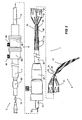
- a stent graft delivery system 1 has a distal end 3 which in use is intended to remain outside a patient and a proximal end 5 which is introduced into the patient.
- a handle arrangement 7 which includes trigger wire release apparatus 9 as will be discussed later.
- the main body of the deployment device includes a tubular carrier 11 which extends from the handle 7 to a distal retention arrangement general shown as 13.
- a guide wire catheter 15 extends out through the distal retention arrangement 13 a nd extends to a nose cone dilator 17 at the proximal end of the deployment device 1.
- the nose cone dilator 17 is curved and in the embodiment shown in Fig. 1 the guide wire catheter 15 is also curved towards its proximal end so that the proximal end 5 of the deployment device has a curve which may have a radius of curvature 19 of between 70 to 150 millimetres. This curvature enables the stent graft deployment device of the present invention to be introduced into the thoracic arch of a patient without excessive load being placed on the walls of the aorta.
- a stent graft 21 is retained on the deployment device between the distal end 23 of the nose cone dilator 17 and the distal retention arrangement 13.
- a sleeve 25 fits over the tubular carrier 11 and by operation of a sleeve manipulator 27 the sleeve can be extended forward to extend to the nose cone dilator 17.
- the stent graft 21 can be held in a constrained position within the sleeve.
- a proximal retention arrangement 31 is provided.
- the proximal retention arrangement 31 includes a trigger wire 33 which engages a knot 35 of suture material which is fastened to the trigger wire 33 and the guide wire catheter 15.
- the nose cone dilator 17 can have one or more apertures extending longitudinally, and the proximal trigger wire 33 can extend into one of these apertures.
- the distal retention arrangement 13 as shown in detail in Fig. 4 includes a capsule 40 which is part of a capsule assembly 41 which is joined by a screw thread 43 to the proximal end 42 of the central carrier 11.
- the capsule 40 includes a passageway 44 within it with a distal closed end 46 and an open proximal end 48.
- the open proximal end 48 faces the nose cone dilator 17 and the guide wire catheter 15 passes through the center of passageway 44.
- the stent graft 21 has a distally extending exposed stent 48 and this distally extending exposed stent 48 is received within the capsule 40 which holds it constrained during deployment. If the distally extending exposed stent 48 has barbs extending from its struts then the capsule keeps the barbs from prematurely engaging the walls of the vessel it is being deployed in and also prevents them from catching in the sleeve 25.
- a trigger wire 50 passes through aperture 52 in the side of the capsule, engages a loop of the exposed stent 48 within the capsule and then passes along the annular recess 54 between the guide wire catheter 15 and the tubular carrier 11 to the trigger wire release mechanism 9.
- the trigger wire release mechanism 9 includes a distal release mechanism 56 and a proximal end release mechanism 58.
- the sleeve 25 is withdrawn by pulling back on the sleeve manipulator 27 while holding the handle 7 stationary.
- the distal release mechanism 56 on the handle 7 is then released by loosening the thumb screw 60 and completely withdrawing the distal release mechanism 56 which pulls out the trigger wire 50 from the capsule 40.
- Pin vice 62 which fixes the position of the guide wire catheter with aspect to the handle 7 and central carrier 11 is then loosened so that the guide wire catheter 15 can be held stationary which holds the nose cone dilator and hence the proximal retention arrangement 31 stationary while the handle is pulled back to remove the capsule 40 from the exposed stent 48 which releases the distal end of the stent graft.
- the proximal release mechanism 58 can then be removed by release of the thumb screw 64 and complete removal of the proximal release mechanism 58 which pulls the guide wire 33 from the proximal end of the stent graft which releases the suture knot 35 which releases the proximal end of the stent graft.
- the tubular central carrier 11 can then be advanced while holding the nose cone dilator 17 stationary so that the deployment device can be made more compact for withdrawal.
- Fig. 3 shows an alternative embodiment of nose cone dilator.
- the guide wire catheter 15 is substantially straight and the curved proximal end of the deployment device has a curvature only in the region of the nose cone dilator 66.
- the radius of curvature of this nose cone dilator may be in the range of 100 to 150 millimetres and it can have a length of from 80 mm as shown by 66a up to 100 mm as shown by 66.
Abstract
Description
- This invention relates to the field of medical devices and more particularly to devices for introduction of vascular devices into the body of a human or animal.
- In recent years endovascular implantable devices have been developed for treatment of aortic aneurysm. These devices are delivered to the treatment site through the vascular system of the patient rather than by open surgery. The devices include a tubular or cylindrical framework or scaffolding of one or more stents to which is secured a tubular shape of graft material such as woven Dacron, polyester polytetrafluoroethylene or the like. The devices are initially reduced to a small diameter, placed into the leading or proximal end of a catheter delivery system whereafter the delivery system is inserted into the vascular system of the patient such as through a femoral incision. The leading end of the delivery system is manoeuvred to the treatment site over a previously positioned guide wire. Through manipulation of a control system that extends to the proximal end of the catheter from the distal end of the system outside the patient the implantable device is then deployed by holding the device at its location and drawing a surrounding sheath. The stent graft or implantable device can then self expand or is expanded through the use of a balloon which is introduced with the stent graft introducible device. The stent graft becomes anchored into position to healthy wall tissue in the aorta such as by barbs whereafter the delivery system is then removed leaving the device in position for reversing an aneurysm in the aorta. All blood flow is channelled through the stent graft so that no blood flow enters the aneurysm thereafter, such that not only does the aneurysm no longer continue to grow and possibly rupture but the aneurysm actually begins to shrink and commonly disappears entirely.
- For treatment of thoracic aortic aneurysms in particular it is necessary to introduce the implantable device high up in the aorta and in a region of the aorta which is curved and where there can be strong blood flow.
US 6346118 B1 shows a prior art stent delivery system. - If an implantable device which is essentially a tube is deployed in the thoracic arch by first releasing the proximal end, that is the end nearer the heart, then blood flow could inflate the stent graft in the manner of a wind sock and there will be considerable pressure of blood flow to displace the implantable device from its intended position.
- It is desirable therefore that a deployment device or deployment system is provided which enables release of the distal end of a stent graft or implantable device before the proximal end.
- It is the object of this invention to provide a device which will overcome at least some of these problems or at least provide the physician with a useful alternative.
- According to the present invention, there is provided a stent graft delivery system for a thoracic aorta stent graft as specified in
claim 1. - In one embodiment the tubular central carrier and nose cone dilator together are curved to provide a curved proximal end which can have a radius of curvature of from 70 to 150 millimetres. Alternatively just the nose cone dilator is curved.
- The capsule provides a first retention arrangement on the tubular carrier for the distal end of a stent graft. Preferably the first retention arrangement includes an aperture extending through the capsule and a distal trigger wire extending along the tubular carrier and extendable through the aperture. Preferably the distal trigger wire extends through the longitudinal lumen.
- There can be a second retention arrangement on the tubular carrier for the proximal end of the stent graft. The second retention arrangement can be distal of the nose cone dilator.
- The nose cone dilator can have one or more apertures extending longitudinally therein and wherein the delivery system can include one or more proximal trigger wires extending longitudinally along said tubular carrier and independently extendable into said one or more apertures of said nose cone.
- The invention as claimed is said to reside in a stent graft deployment apparatus comprising; a deployment catheter having a proximal end adapted to be introduced into a patient and a distal end adapted to remain outside a patient, the catheter having at a proximal end thereof a region adapted in use to contain a stent graft; a sheath arrangement adapted in use to extend over and cover the region adapted to be moved with respect to the catheter to expose the region to thereby enable deployment of the stent graft; a nose cone dilator positioned at the proximal end of the deployment catheter; a distal retention arrangement for the stent graft at a distal end of the region and comprising a capsule having a passageway extending therein with a distal closed end and an open proximal end facing the nose cone dilator.
- The proximal retention arrangement can include at least one proximal trigger wire with the trigger wire extending from the outside of the patient where it is retained by a trigger wire release mechanism on a handle at the distal end of the deployment catheter.
-
-
Fig. 1 shows a general view of a stent graft delivery system according to one embodiment of the present invention with a stent graft partially released; -
Fig. 2 shows a part cross-sectional view of the embodiment shown inFig. 1 ; -
Fig. 3 shows one embodiment of nose cone dilator according to the invention; and -
Fig. 4 shows a part cross-sectional view of the capsule portion of a deployment device according to an embodiment of this invention. -
US Patent No. 5,387,235 entitled "Expandable Transluminal Graft Prosthesis For Repair Of Aneurysm" discloses apparatus and methods of retaining grafts onto deployment devices. These features and other features disclosed inU.S. Patent No. 5,387,235 could be used with the present invention. -
U.S. Patent No. 5,720,776 entitled "Barb and Expandable Transluminal Graft Prosthesis for Repair of Aneurysm" discloses improved barbs with various forms of mechanical attachment to a stent. These features and other features disclosed inU.S. Patent No. 5,720,776 could be used with the present invention. -
U.S. Patent No. 6,206,931 entitled "Graft Prosthesis Materials" discloses graft prosthesis materials and a method forimplanting,transplanting replacing and repairing a part of a patient and particularly the manufacture and use of a purified, collagen based matrix structure removed from a submucosa tissue source. These features and other features disclosed inU.S. Patent No. 6,206,931 could be used with the present invention. -
PCT Patent Publication No. WO 98/53761 PCT Patent Publication No. WO 98/53761 -
PCT Patent Publication No. WO 99/29262 PCT Patent Publication No. WO 99/29262 -
PCT Patent Publication Number WO 03/034948 PCT Patent Publication No. WO 03/034948 -
U.S. Provisional Patent Application Serial No. 60/392,682, filed June 28, 2003 U.S. Provisional Patent Application Serial No. 60/392,682 could be used with the present invention. -
U.S. Provisional Patent Application Serial No. 60/392,667, filed June 28, 2002 U.S. Provisional Patent Application Serial No. 60/392,667 could be used with the present invention. -
U.S. Provisional Patent Application Serial Number 60/392,599, filed June 28,2002U.S. Provisional Patent Application Serial No. 60/392,599 , could be used with the present invention. -
U.S. Provisional Patent Application Serial No. 60/391,737, filed June 26, 2002 U.S. Provisional Patent Application Serial No. 60/391,737 could be used with the present invention. -
U.S. Provisional Patent Application No. 60/405,367, filed August 23,2002 U.S. Provisional Patent Application No. 60/405,367 could be used with the present invention. -
U.S. Patent Application Serial No. 10/322,862, filed December 18,2002 U.S. Patent Application Serial No. 10/322,862 could be used with the present invention. - This then generally describes the invention but to assist with the understanding, reference will now be made to the accompanying drawings which show a preferred embodiment of the invention.
- Now looking more closely at
Figs. 1 and2 it will be seen that a stentgraft delivery system 1 according to the invention has adistal end 3 which in use is intended to remain outside a patient and aproximal end 5 which is introduced into the patient. - Towards the distal end there is a handle arrangement 7 which includes trigger
wire release apparatus 9 as will be discussed later. The main body of the deployment device includes atubular carrier 11 which extends from the handle 7 to a distal retention arrangement general shown as 13. - Within a
longitudinal lumen 14 in thecentral carrier 11 extends aguide wire catheter 15. Theguide wire catheter 15 extends out through the distal retention arrangement 13 a nd extends to anose cone dilator 17 at the proximal end of thedeployment device 1. Thenose cone dilator 17 is curved and in the embodiment shown inFig. 1 theguide wire catheter 15 is also curved towards its proximal end so that theproximal end 5 of the deployment device has a curve which may have a radius ofcurvature 19 of between 70 to 150 millimetres. This curvature enables the stent graft deployment device of the present invention to be introduced into the thoracic arch of a patient without excessive load being placed on the walls of the aorta. - A
stent graft 21 is retained on the deployment device between thedistal end 23 of thenose cone dilator 17 and thedistal retention arrangement 13. Asleeve 25 fits over thetubular carrier 11 and by operation of asleeve manipulator 27 the sleeve can be extended forward to extend to thenose cone dilator 17. By the use of thesleeve 25 thestent graft 21 can be held in a constrained position within the sleeve. - At the proximal end of the stent graft just distal of the
distal end 23 of the nose cone dilator 17 aproximal retention arrangement 31 is provided. - The
proximal retention arrangement 31 includes atrigger wire 33 which engages aknot 35 of suture material which is fastened to thetrigger wire 33 and theguide wire catheter 15. When thetrigger wire 33 is withdrawn as will be discussed later, thesuture knot 25 is released and the proximal end of the stent graft can be released. Thenose cone dilator 17 can have one or more apertures extending longitudinally, and theproximal trigger wire 33 can extend into one of these apertures. - The
distal retention arrangement 13 as shown in detail inFig. 4 includes acapsule 40 which is part of acapsule assembly 41 which is joined by ascrew thread 43 to theproximal end 42 of thecentral carrier 11. Thecapsule 40 includes apassageway 44 within it with a distalclosed end 46 and an openproximal end 48. The openproximal end 48 faces thenose cone dilator 17 and theguide wire catheter 15 passes through the center ofpassageway 44. - The
stent graft 21 has a distally extending exposedstent 48 and this distally extending exposedstent 48 is received within thecapsule 40 which holds it constrained during deployment. If the distally extending exposedstent 48 has barbs extending from its struts then the capsule keeps the barbs from prematurely engaging the walls of the vessel it is being deployed in and also prevents them from catching in thesleeve 25. Atrigger wire 50 passes throughaperture 52 in the side of the capsule, engages a loop of the exposedstent 48 within the capsule and then passes along theannular recess 54 between theguide wire catheter 15 and thetubular carrier 11 to the triggerwire release mechanism 9. - The trigger
wire release mechanism 9 includes adistal release mechanism 56 and a proximalend release mechanism 58. - To release the stent graft after it has been placed in the desired position in the thoracic arch, the
sleeve 25 is withdrawn by pulling back on thesleeve manipulator 27 while holding the handle 7 stationary. Thedistal release mechanism 56 on the handle 7 is then released by loosening thethumb screw 60 and completely withdrawing thedistal release mechanism 56 which pulls out thetrigger wire 50 from thecapsule 40.Pin vice 62 which fixes the position of the guide wire catheter with aspect to the handle 7 andcentral carrier 11 is then loosened so that theguide wire catheter 15 can be held stationary which holds the nose cone dilator and hence theproximal retention arrangement 31 stationary while the handle is pulled back to remove thecapsule 40 from the exposedstent 48 which releases the distal end of the stent graft. - Once the position of the proximal end of the
stent grift 21 has been checked, theproximal release mechanism 58 can then be removed by release of thethumb screw 64 and complete removal of theproximal release mechanism 58 which pulls theguide wire 33 from the proximal end of the stent graft which releases thesuture knot 35 which releases the proximal end of the stent graft. - The tubular
central carrier 11 can then be advanced while holding thenose cone dilator 17 stationary so that the deployment device can be made more compact for withdrawal. -
Fig. 3 shows an alternative embodiment of nose cone dilator. In this embodiment, theguide wire catheter 15 is substantially straight and the curved proximal end of the deployment device has a curvature only in the region of thenose cone dilator 66. The radius of curvature of this nose cone dilator may be in the range of 100 to 150 millimetres and it can have a length of from 80 mm as shown by 66a up to 100 mm as shown by 66. - Throughout this specification various indications have been given as to the scope of the invention but the invention is not limited to any one of these but may reside in two or more of these combined together. The examples are given for illustration only and not for limitation.
Claims (6)
- A stent graft delivery system (1) for a thoracic aorta stent graft (21) comprising:a tubular central carrier (11) having a distal end and a proximal end,a longitudinal lumen (14) through the tubular central carrier (11),a guide wire catheter (15) extending through the longitudinal lumen (14) and proximally of the tubular central carrier (11),a nose cone dilator (17) at the proximal end of the guide wire catheter (15) a capsule (40) having a passageway (44) extending therein with a distal closed end (46) attached to the tubular central carrier (11) and an open proximal end (48) facing the nose cone dilator (17),the capsule being adapted to receive the distal end of the stent graft (21) and the nose cone dilator (17) having a curved proximal end, and further including a second proximal retention arrangement (31) on the distal end of the nose cone dilator (17) for the proximal end of the stent graft (21) wherein the proximal retention arrangement includes at least one proximal trigger wire (33).
- A stent graft delivery system as in claim 1 wherein the curved proximal end has a radius of curvature of from 70 to 160 millimeters.
- A stent graft delivery system as in claim 1 comprising a coaxial sheath over the tubular central carrier, the coaxial sheath being movable with respect to the tubular central carrier and extending to the nose cone dilator.
- A stent graft delivery system as in claim 1 wherein the capsule includes an aperture extending through the capsule and a distal trigger wire which extends along the longitudinal lumen and through the aperture.
- A stent graft deployment apparatus as in claim 1 wherein the proximal trigger wire extends from the outside of a patient in use where it is retained by a trigger wire release mechanism on a handle at the distal end of the tubular central carrier.
- A stent graft deployment apparatus as in claim 4 wherein the distal trigger wire extends from the outside of a patient where it is retained by a trigger wire release mechanism on a handle at the distal end of the tubular central carrier.
Applications Claiming Priority (3)
| Application Number | Priority Date | Filing Date | Title |
|---|---|---|---|
| US39259902P | 2002-06-28 | 2002-06-28 | |
| US392599P | 2002-06-28 | ||
| PCT/US2003/020651 WO2004002371A2 (en) | 2002-06-28 | 2003-06-30 | Thoracic stent-graft introducer |
Publications (2)
| Publication Number | Publication Date |
|---|---|
| EP1517652A2 EP1517652A2 (en) | 2005-03-30 |
| EP1517652B1 true EP1517652B1 (en) | 2011-12-07 |
Family
ID=30000900
Family Applications (2)
| Application Number | Title | Priority Date | Filing Date |
|---|---|---|---|
| EP03762263A Expired - Lifetime EP1517651B1 (en) | 2002-06-28 | 2003-06-30 | Thoracic aortic aneurysm stent graft |
| EP03762267A Expired - Lifetime EP1517652B1 (en) | 2002-06-28 | 2003-06-30 | Thoracic introducer |
Family Applications Before (1)
| Application Number | Title | Priority Date | Filing Date |
|---|---|---|---|
| EP03762263A Expired - Lifetime EP1517651B1 (en) | 2002-06-28 | 2003-06-30 | Thoracic aortic aneurysm stent graft |
Country Status (9)
| Country | Link |
|---|---|
| US (2) | US7611529B2 (en) |
| EP (2) | EP1517651B1 (en) |
| JP (3) | JP4743836B2 (en) |
| AT (2) | ATE536148T1 (en) |
| AU (2) | AU2003258976B2 (en) |
| CA (2) | CA2489495C (en) |
| DE (1) | DE60332733D1 (en) |
| DK (2) | DK1517652T3 (en) |
| WO (2) | WO2004002371A2 (en) |
Families Citing this family (268)
| Publication number | Priority date | Publication date | Assignee | Title |
|---|---|---|---|---|
| US6395019B2 (en) | 1998-02-09 | 2002-05-28 | Trivascular, Inc. | Endovascular graft |
| US20070265563A1 (en) * | 2006-05-11 | 2007-11-15 | Heuser Richard R | Device for treating chronic total occlusion |
| FR2811218B1 (en) | 2000-07-05 | 2003-02-28 | Patrice Suslian | IMPLANTABLE DEVICE FOR CORRECTING URINARY INCONTINENCE |
| GB0025068D0 (en) | 2000-10-12 | 2000-11-29 | Browning Healthcare Ltd | Apparatus and method for treating female urinary incontinence |
| US20060205995A1 (en) | 2000-10-12 | 2006-09-14 | Gyne Ideas Limited | Apparatus and method for treating female urinary incontinence |
| US8167785B2 (en) | 2000-10-12 | 2012-05-01 | Coloplast A/S | Urethral support system |
| GB0108088D0 (en) | 2001-03-30 | 2001-05-23 | Browning Healthcare Ltd | Surgical implant |
| US20100016943A1 (en) | 2001-12-20 | 2010-01-21 | Trivascular2, Inc. | Method of delivering advanced endovascular graft |
| US7147661B2 (en) * | 2001-12-20 | 2006-12-12 | Boston Scientific Santa Rosa Corp. | Radially expandable stent |
| EP1517651B1 (en) | 2002-06-28 | 2010-05-26 | Cook Incorporated | Thoracic aortic aneurysm stent graft |
| CA2492630C (en) | 2002-08-02 | 2009-01-13 | C.R. Bard, Inc. | Self anchoring sling and introducer system |
| US7550004B2 (en) * | 2002-08-20 | 2009-06-23 | Cook Biotech Incorporated | Endoluminal device with extracellular matrix material and methods |
| DK1545396T3 (en) * | 2002-08-23 | 2009-03-02 | Cook William A Australia | composite prosthesis |
| US7300459B2 (en) * | 2002-10-17 | 2007-11-27 | Heuser Richard R | Stent with covering and differential dilation |
| US9125733B2 (en) | 2003-01-14 | 2015-09-08 | The Cleveland Clinic Foundation | Branched vessel endoluminal device |
| US7166088B2 (en) | 2003-01-27 | 2007-01-23 | Heuser Richard R | Catheter introducer system |
| GB0307082D0 (en) | 2003-03-27 | 2003-04-30 | Gyne Ideas Ltd | Drug delivery device and method |
| DE602004024972D1 (en) * | 2003-04-08 | 2010-02-25 | Cook Inc | INTRALUMINAL SUPPORT WITH GRAFT |
| US7279003B2 (en) * | 2003-04-24 | 2007-10-09 | Medtronic Vascular, Inc. | Stent graft tapered spring |
| US7101390B2 (en) * | 2003-05-27 | 2006-09-05 | Scimed Life Systems, Inc. | Staged deployment endograft |
| US8721710B2 (en) * | 2003-08-11 | 2014-05-13 | Hdh Medical Ltd. | Anastomosis system and method |
| US7402141B2 (en) * | 2003-08-27 | 2008-07-22 | Heuser Richard R | Catheter guidewire system using concentric wires |
| US8500792B2 (en) | 2003-09-03 | 2013-08-06 | Bolton Medical, Inc. | Dual capture device for stent graft delivery system and method for capturing a stent graft |
| US20070198078A1 (en) | 2003-09-03 | 2007-08-23 | Bolton Medical, Inc. | Delivery system and method for self-centering a Proximal end of a stent graft |
| US7763063B2 (en) | 2003-09-03 | 2010-07-27 | Bolton Medical, Inc. | Self-aligning stent graft delivery system, kit, and method |
| US9198786B2 (en) | 2003-09-03 | 2015-12-01 | Bolton Medical, Inc. | Lumen repair device with capture structure |
| US11259945B2 (en) | 2003-09-03 | 2022-03-01 | Bolton Medical, Inc. | Dual capture device for stent graft delivery system and method for capturing a stent graft |
| US8292943B2 (en) | 2003-09-03 | 2012-10-23 | Bolton Medical, Inc. | Stent graft with longitudinal support member |
| US20080264102A1 (en) | 2004-02-23 | 2008-10-30 | Bolton Medical, Inc. | Sheath Capture Device for Stent Graft Delivery System and Method for Operating Same |
| US11596537B2 (en) | 2003-09-03 | 2023-03-07 | Bolton Medical, Inc. | Delivery system and method for self-centering a proximal end of a stent graft |
| AU2004270239C1 (en) * | 2003-09-04 | 2011-07-07 | Cook Biotech Incorporated | Extracellular matrix composite materials, and manufacture and use thereof |
| EP3045136B1 (en) | 2003-09-12 | 2021-02-24 | Vessix Vascular, Inc. | Selectable eccentric remodeling and/or ablation of atherosclerotic material |
| WO2005034807A1 (en) | 2003-10-10 | 2005-04-21 | William A. Cook Australia Pty. Ltd | Composite stent graft |
| ATE440564T1 (en) * | 2003-10-10 | 2009-09-15 | Cleveland Clinic Foundation | ENDOLUMINAL PROSTHESIS WITH CONNECTABLE MODULES |
| US8043357B2 (en) | 2003-10-10 | 2011-10-25 | Cook Medical Technologies Llc | Ring stent |
| CA2540830C (en) | 2003-10-10 | 2012-08-14 | William A. Cook Australia Pty. Ltd. | Fenestrated stent grafts |
| US7998186B2 (en) | 2003-10-14 | 2011-08-16 | William A. Cook Australia Pty. Ltd. | Introducer for a side branch device |
| EP1691719B1 (en) | 2003-10-14 | 2016-09-14 | Cook Medical Technologies LLC | Introducer for an iliac side branch device |
| IL158960A0 (en) | 2003-11-19 | 2004-05-12 | Neovasc Medical Ltd | Vascular implant |
| ATE499073T1 (en) * | 2004-01-20 | 2011-03-15 | Cook Inc | MULTIPLE STITCHES TO ATTACH A STENT TO A PROSTHESIS |
| US8998973B2 (en) | 2004-03-02 | 2015-04-07 | Boston Scientific Scimed, Inc. | Medical devices including metallic films |
| US8591568B2 (en) | 2004-03-02 | 2013-11-26 | Boston Scientific Scimed, Inc. | Medical devices including metallic films and methods for making same |
| US7901447B2 (en) | 2004-12-29 | 2011-03-08 | Boston Scientific Scimed, Inc. | Medical devices including a metallic film and at least one filament |
| US8992592B2 (en) | 2004-12-29 | 2015-03-31 | Boston Scientific Scimed, Inc. | Medical devices including metallic films |
| US8632580B2 (en) | 2004-12-29 | 2014-01-21 | Boston Scientific Scimed, Inc. | Flexible medical devices including metallic films |
| AU2005232726B2 (en) * | 2004-04-12 | 2010-07-15 | Cook Medical Technologies Llc | Stent graft repair device |
| GB0411360D0 (en) | 2004-05-21 | 2004-06-23 | Mpathy Medical Devices Ltd | Implant |
| US8043354B2 (en) | 2004-06-16 | 2011-10-25 | William A. Cook Australia Pty. Ltd. | Thoracic deployment device and stent graft |
| US20090012429A1 (en) * | 2004-08-25 | 2009-01-08 | Heuser Richard R | Catheter guidewire system using concentric wires |
| US8545418B2 (en) | 2004-08-25 | 2013-10-01 | Richard R. Heuser | Systems and methods for ablation of occlusions within blood vessels |
| GB0419954D0 (en) | 2004-09-08 | 2004-10-13 | Advotek Medical Devices Ltd | System for directing therapy |
| US9713730B2 (en) | 2004-09-10 | 2017-07-25 | Boston Scientific Scimed, Inc. | Apparatus and method for treatment of in-stent restenosis |
| US8396548B2 (en) | 2008-11-14 | 2013-03-12 | Vessix Vascular, Inc. | Selective drug delivery in a lumen |
| US8920414B2 (en) | 2004-09-10 | 2014-12-30 | Vessix Vascular, Inc. | Tuned RF energy and electrical tissue characterization for selective treatment of target tissues |
| US7699883B2 (en) * | 2004-10-25 | 2010-04-20 | Myles Douglas | Vascular graft and deployment system |
| WO2006071243A1 (en) * | 2004-12-29 | 2006-07-06 | Boston Scientific Limited | Medical devices including metallic films and methods for making same |
| US8454678B2 (en) * | 2005-03-19 | 2013-06-04 | Cook Biotech Incorporated | Prosthetic implants including ECM composite material |
| US7854760B2 (en) | 2005-05-16 | 2010-12-21 | Boston Scientific Scimed, Inc. | Medical devices including metallic films |
| US20060276883A1 (en) * | 2005-06-01 | 2006-12-07 | Cook Incorporated | Tapered and distally stented elephant trunk stent graft |
| US20080109058A1 (en) * | 2005-06-01 | 2008-05-08 | Cook Incorporated | Intraoperative Anastomosis Method |
| GB2427554B (en) * | 2005-06-23 | 2007-05-23 | Vascutek Ltd | Aneurysm graft with markers |
| CA2615535C (en) | 2005-07-27 | 2013-12-24 | Cook Critical Care Incorporated | Stent/graft device and method for open surgical placement |
| WO2007035895A2 (en) * | 2005-09-21 | 2007-03-29 | Cook Incorporated | Endoluminal stent graft delivery assembly |
| US7399314B2 (en) * | 2005-11-15 | 2008-07-15 | Cordis Corporation | Systems and methods for securing graft material to intraluminal devices |
| US8709060B2 (en) * | 2005-12-23 | 2014-04-29 | Cook Medical Technologies Llc | Prosthesis deployment system |
| JP5499375B2 (en) * | 2006-01-18 | 2014-05-21 | クック・メディカル・テクノロジーズ・リミテッド・ライアビリティ・カンパニー | Intracavity delivery device |
| US8062321B2 (en) | 2006-01-25 | 2011-11-22 | Pq Bypass, Inc. | Catheter system for connecting adjacent blood vessels |
| US8518098B2 (en) | 2006-02-21 | 2013-08-27 | Cook Medical Technologies Llc | Split sheath deployment system |
| WO2007100716A2 (en) * | 2006-02-27 | 2007-09-07 | William A. Cook Australia Pty. Ltd. | Retention of stents |
| US8357194B2 (en) * | 2006-03-15 | 2013-01-22 | Cordis Corporation | Stent graft device |
| US9308105B2 (en) * | 2006-04-19 | 2016-04-12 | Cook Medical Technologies Llc | Delivery device for an endoluminal prosthesis |
| CN101484090B (en) * | 2006-04-19 | 2011-04-27 | 威廉A·库克澳大利亚有限公司 | Twin bifurcated stent graft |
| US20130190676A1 (en) | 2006-04-20 | 2013-07-25 | Limflow Gmbh | Devices and methods for fluid flow through body passages |
| US8019435B2 (en) | 2006-05-02 | 2011-09-13 | Boston Scientific Scimed, Inc. | Control of arterial smooth muscle tone |
| US8118853B2 (en) * | 2006-06-19 | 2012-02-21 | Cook Medical Technologies Llc | Prosthesis delivery and deployment device |
| US7722665B2 (en) * | 2006-07-07 | 2010-05-25 | Graft Technologies, Inc. | System and method for providing a graft in a vascular environment |
| US7892275B2 (en) * | 2006-07-24 | 2011-02-22 | William A. Cook Australia Pty. Ltd. | Docking arrangement |
| EP2076194B1 (en) | 2006-10-18 | 2013-04-24 | Vessix Vascular, Inc. | System for inducing desirable temperature effects on body tissue |
| EP2992850A1 (en) | 2006-10-18 | 2016-03-09 | Vessix Vascular, Inc. | Inducing desirable temperature effects on body tissue |
| EP2079397B1 (en) * | 2006-10-24 | 2010-03-24 | Cook Incorporated | Stent member |
| US8317856B2 (en) | 2007-03-05 | 2012-11-27 | Endospan Ltd. | Multi-component expandable supportive bifurcated endoluminal grafts and methods for using same |
| US7766953B2 (en) * | 2007-05-16 | 2010-08-03 | Med Institute, Inc. | Deployment system for an expandable stent |
| US9119742B2 (en) * | 2007-07-16 | 2015-09-01 | Cook Medical Technologies Llc | Prosthesis delivery and deployment device |
| JP5364933B2 (en) * | 2007-08-13 | 2013-12-11 | クック・メディカル・テクノロジーズ・リミテッド・ライアビリティ・カンパニー | Placement device |
| US8226701B2 (en) | 2007-09-26 | 2012-07-24 | Trivascular, Inc. | Stent and delivery system for deployment thereof |
| US8663309B2 (en) | 2007-09-26 | 2014-03-04 | Trivascular, Inc. | Asymmetric stent apparatus and method |
| US8066755B2 (en) | 2007-09-26 | 2011-11-29 | Trivascular, Inc. | System and method of pivoted stent deployment |
| EP2194921B1 (en) | 2007-10-04 | 2018-08-29 | TriVascular, Inc. | Modular vascular graft for low profile percutaneous delivery |
| US9474641B2 (en) * | 2007-10-23 | 2016-10-25 | Cook Medical Technologies Llc | Indwelling catheter arrangement |
| WO2009055574A2 (en) | 2007-10-26 | 2009-04-30 | Cook Critical Care Incorporated | Vascular conduit and delivery system for open surgical placement |
| US7972374B2 (en) * | 2007-10-29 | 2011-07-05 | Cleveland Clinic Foundation | Securing rods and modular graft systems |
| US9107741B2 (en) | 2007-11-01 | 2015-08-18 | Cook Medical Technologies Llc | Flexible stent graft |
| EP2210248B1 (en) * | 2007-11-13 | 2016-04-20 | Cook Medical Technologies LLC | Intraluminal bypass prosthesis |
| US8083789B2 (en) | 2007-11-16 | 2011-12-27 | Trivascular, Inc. | Securement assembly and method for expandable endovascular device |
| US8328861B2 (en) | 2007-11-16 | 2012-12-11 | Trivascular, Inc. | Delivery system and method for bifurcated graft |
| CN101965162B (en) | 2007-12-15 | 2014-12-10 | 恩多斯潘有限公司 | Extra-vascular wrapping for treating aneurysmatic aorta in conjunction with endovascular stent-graft and methods thereof |
| US9226813B2 (en) | 2007-12-26 | 2016-01-05 | Cook Medical Technologies Llc | Low profile non-symmetrical stent |
| GB2476451A (en) * | 2009-11-19 | 2011-06-29 | Cook William Europ | Stent Graft |
| US9180030B2 (en) | 2007-12-26 | 2015-11-10 | Cook Medical Technologies Llc | Low profile non-symmetrical stent |
| US8574284B2 (en) | 2007-12-26 | 2013-11-05 | Cook Medical Technologies Llc | Low profile non-symmetrical bare alignment stents with graft |
| GB2475494B (en) | 2009-11-18 | 2011-11-23 | Cook William Europ | Stent graft and introducer assembly |
| WO2009091899A2 (en) | 2008-01-17 | 2009-07-23 | Boston Scientific Scimed, Inc. | Stent with anti-migration feature |
| WO2009105699A1 (en) | 2008-02-22 | 2009-08-27 | Endologix, Inc. | Design and method of placement of a graft or graft system |
| KR20090108143A (en) * | 2008-04-11 | 2009-10-15 | 주식회사 에스앤지바이오텍 | Stent used in blood vessel |
| US10456554B2 (en) * | 2008-04-17 | 2019-10-29 | W. L. Gore & Associates, Inc. | Device delivery catheter having a curved distal tip |
| US20090264898A1 (en) * | 2008-04-17 | 2009-10-22 | Medtronic Vascular, Inc. | Steerable Endovascular Retrieval Device |
| US20100305686A1 (en) * | 2008-05-15 | 2010-12-02 | Cragg Andrew H | Low-profile modular abdominal aortic aneurysm graft |
| BRPI0913877A2 (en) | 2008-06-30 | 2015-10-27 | Bolton Medical Inc | abdominal aortic aneurysms: systems and methods of use |
| KR100958578B1 (en) * | 2008-07-16 | 2010-05-18 | 주식회사 에스앤지바이오텍 | Stent used in blood vessel |
| AU2009271596B2 (en) * | 2008-07-18 | 2014-06-05 | Cook Medical Technologies Llc | Introducer for endovascular implants |
| US8845715B2 (en) * | 2008-08-18 | 2014-09-30 | Hisham M. F. SHERIF | Total aortic arch reconstruction graft |
| EP2317958B1 (en) * | 2008-08-26 | 2012-02-29 | William A. Cook Australia Pty. Ltd. | Thoracic introducer |
| GB2464978B (en) * | 2008-10-31 | 2010-10-20 | Cook William Europ | Introducer for deploying a stent graft in a curved lumen |
| US11376114B2 (en) | 2008-10-31 | 2022-07-05 | Cook Medical Technologies Llc | Introducer for deploying a stent graft in a curved lumen and stent graft therefor |
| GB2464977B (en) * | 2008-10-31 | 2010-11-03 | William Cook Europe As | Introducer for deploying a stent graft in a curved lumen and stent graft therefor |
| CA2743992A1 (en) | 2008-11-17 | 2010-05-20 | Minnow Medical, Inc. | Selective accumulation of energy with or without knowledge of tissue topography |
| US8734502B2 (en) * | 2008-12-17 | 2014-05-27 | Cook Medical Technologies Llc | Tapered stent and flexible prosthesis |
| AU2009200350B1 (en) * | 2009-02-02 | 2009-07-16 | Cook Incorporated | Preloaded stent graft delivery device |
| AU2010223953B2 (en) | 2009-03-13 | 2014-05-01 | Bolton Medical, Inc. | System and method for deploying an endoluminal prosthesis at a surgical site |
| WO2010126889A1 (en) | 2009-04-27 | 2010-11-04 | Med Institute, Inc. | Stent with protected barbs |
| EP2429452B1 (en) | 2009-04-28 | 2020-01-15 | Endologix, Inc. | Endoluminal prosthesis system |
| US8858613B2 (en) | 2010-09-20 | 2014-10-14 | Altura Medical, Inc. | Stent graft delivery systems and associated methods |
| EP3434225B1 (en) | 2009-06-23 | 2023-11-01 | Endospan Ltd. | Vascular prosthesis for treating aneurysms |
| WO2011004374A1 (en) | 2009-07-09 | 2011-01-13 | Endospan Ltd. | Apparatus for closure of a lumen and methods of using the same |
| US9095456B2 (en) | 2009-10-13 | 2015-08-04 | Cook Medical Technologies Llc | Paraplegia prevention stent graft |
| WO2011047004A1 (en) | 2009-10-13 | 2011-04-21 | William Cook Europe Aps | Paraplegia prevention stent graft |
| US9757263B2 (en) | 2009-11-18 | 2017-09-12 | Cook Medical Technologies Llc | Stent graft and introducer assembly |
| CA2782357C (en) | 2009-11-30 | 2018-06-05 | Endospan Ltd. | Multi-component stent-graft system for implantation in a blood vessel with multiple branches |
| US9572652B2 (en) * | 2009-12-01 | 2017-02-21 | Altura Medical, Inc. | Modular endograft devices and associated systems and methods |
| US9101457B2 (en) | 2009-12-08 | 2015-08-11 | Endospan Ltd. | Endovascular stent-graft system with fenestrated and crossing stent-grafts |
| CA2785953C (en) | 2009-12-31 | 2016-02-16 | Endospan Ltd. | Endovascular flow direction indicator |
| EP2533722B1 (en) | 2010-02-08 | 2017-03-29 | Endospan Ltd. | Thermal energy application for prevention and management of endoleaks in stent-grafts |
| CN103068330B (en) | 2010-04-09 | 2016-06-29 | Vessix血管股份有限公司 | Power for treating tissue occurs and controls device |
| US9192790B2 (en) | 2010-04-14 | 2015-11-24 | Boston Scientific Scimed, Inc. | Focused ultrasonic renal denervation |
| US8473067B2 (en) | 2010-06-11 | 2013-06-25 | Boston Scientific Scimed, Inc. | Renal denervation and stimulation employing wireless vascular energy transfer arrangement |
| US9358365B2 (en) | 2010-07-30 | 2016-06-07 | Boston Scientific Scimed, Inc. | Precision electrode movement control for renal nerve ablation |
| US9408661B2 (en) | 2010-07-30 | 2016-08-09 | Patrick A. Haverkost | RF electrodes on multiple flexible wires for renal nerve ablation |
| US9463062B2 (en) | 2010-07-30 | 2016-10-11 | Boston Scientific Scimed, Inc. | Cooled conductive balloon RF catheter for renal nerve ablation |
| US9155589B2 (en) | 2010-07-30 | 2015-10-13 | Boston Scientific Scimed, Inc. | Sequential activation RF electrode set for renal nerve ablation |
| US9084609B2 (en) | 2010-07-30 | 2015-07-21 | Boston Scientific Scime, Inc. | Spiral balloon catheter for renal nerve ablation |
| AU2015202398B2 (en) * | 2010-08-13 | 2017-01-19 | Cook Medical Technologies Llc | Precannulated fenestration |
| CA2747610C (en) * | 2010-08-13 | 2014-09-16 | Cook Medical Technologies Llc | Precannulated fenestration |
| US9101455B2 (en) | 2010-08-13 | 2015-08-11 | Cook Medical Technologies Llc | Preloaded wire for endoluminal device |
| US8974451B2 (en) | 2010-10-25 | 2015-03-10 | Boston Scientific Scimed, Inc. | Renal nerve ablation using conductive fluid jet and RF energy |
| US9220558B2 (en) | 2010-10-27 | 2015-12-29 | Boston Scientific Scimed, Inc. | RF renal denervation catheter with multiple independent electrodes |
| EP2525742B1 (en) | 2010-10-29 | 2015-03-18 | Cook Medical Technologies LLC | Medical device delivery system and deployment method |
| US20120109279A1 (en) | 2010-11-02 | 2012-05-03 | Endologix, Inc. | Apparatus and method of placement of a graft or graft system |
| US9028485B2 (en) | 2010-11-15 | 2015-05-12 | Boston Scientific Scimed, Inc. | Self-expanding cooling electrode for renal nerve ablation |
| US9668811B2 (en) | 2010-11-16 | 2017-06-06 | Boston Scientific Scimed, Inc. | Minimally invasive access for renal nerve ablation |
| US9089350B2 (en) | 2010-11-16 | 2015-07-28 | Boston Scientific Scimed, Inc. | Renal denervation catheter with RF electrode and integral contrast dye injection arrangement |
| US9566149B2 (en) | 2010-11-16 | 2017-02-14 | W. L. Gore & Associates, Inc. | Devices and methods for in situ fenestration of a stent-graft at the site of a branch vessel |
| US9326751B2 (en) | 2010-11-17 | 2016-05-03 | Boston Scientific Scimed, Inc. | Catheter guidance of external energy for renal denervation |
| US9060761B2 (en) | 2010-11-18 | 2015-06-23 | Boston Scientific Scime, Inc. | Catheter-focused magnetic field induced renal nerve ablation |
| US9023034B2 (en) | 2010-11-22 | 2015-05-05 | Boston Scientific Scimed, Inc. | Renal ablation electrode with force-activatable conduction apparatus |
| US9192435B2 (en) | 2010-11-22 | 2015-11-24 | Boston Scientific Scimed, Inc. | Renal denervation catheter with cooled RF electrode |
| US20120157993A1 (en) | 2010-12-15 | 2012-06-21 | Jenson Mark L | Bipolar Off-Wall Electrode Device for Renal Nerve Ablation |
| US9220561B2 (en) | 2011-01-19 | 2015-12-29 | Boston Scientific Scimed, Inc. | Guide-compatible large-electrode catheter for renal nerve ablation with reduced arterial injury |
| US9526638B2 (en) | 2011-02-03 | 2016-12-27 | Endospan Ltd. | Implantable medical devices constructed of shape memory material |
| WO2012111006A1 (en) | 2011-02-17 | 2012-08-23 | Endospan Ltd. | Vascular bands and delivery systems therefor |
| EP2680788A4 (en) | 2011-03-02 | 2014-12-10 | Endospan Ltd | Reduced-strain extra- vascular ring for treating aortic aneurysm |
| EP2517671B1 (en) | 2011-04-28 | 2016-05-11 | Cook Medical Technologies LLC | Apparatus for facilitating deployment of an endoluminal prosthesis |
| US9381078B2 (en) | 2011-04-29 | 2016-07-05 | The Cleveland Clinic Foundation | Power and/or signal trigger wire for an endovascular delivery system |
| US9005267B2 (en) | 2011-04-29 | 2015-04-14 | Cleveland Clinic Foundation | Rotational alignment wire system for an endovascular delivery system |
| US8574287B2 (en) | 2011-06-14 | 2013-11-05 | Endospan Ltd. | Stents incorporating a plurality of strain-distribution locations |
| US8951298B2 (en) | 2011-06-21 | 2015-02-10 | Endospan Ltd. | Endovascular system with circumferentially-overlapping stent-grafts |
| US9254209B2 (en) | 2011-07-07 | 2016-02-09 | Endospan Ltd. | Stent fixation with reduced plastic deformation |
| CN103813745B (en) | 2011-07-20 | 2016-06-29 | 波士顿科学西美德公司 | In order to visualize, be directed at and to melt transcutaneous device and the method for nerve |
| CN103813829B (en) | 2011-07-22 | 2016-05-18 | 波士顿科学西美德公司 | There is the neuromodulation system of the neuromodulation element that can be positioned in spiral guiding piece |
| WO2013030818A2 (en) | 2011-08-28 | 2013-03-07 | Endospan Ltd. | Stent-grafts with post-deployment variable axial and radial displacement |
| US9662196B2 (en) | 2011-09-27 | 2017-05-30 | Cook Medical Technologies Llc | Endoluminal prosthesis with steerable branch |
| WO2013055826A1 (en) | 2011-10-10 | 2013-04-18 | Boston Scientific Scimed, Inc. | Medical devices including ablation electrodes |
| US10085799B2 (en) | 2011-10-11 | 2018-10-02 | Boston Scientific Scimed, Inc. | Off-wall electrode device and methods for nerve modulation |
| US9420955B2 (en) | 2011-10-11 | 2016-08-23 | Boston Scientific Scimed, Inc. | Intravascular temperature monitoring system and method |
| US9364284B2 (en) | 2011-10-12 | 2016-06-14 | Boston Scientific Scimed, Inc. | Method of making an off-wall spacer cage |
| EP2768568B1 (en) | 2011-10-18 | 2020-05-06 | Boston Scientific Scimed, Inc. | Integrated crossing balloon catheter |
| EP2768563B1 (en) | 2011-10-18 | 2016-11-09 | Boston Scientific Scimed, Inc. | Deflectable medical devices |
| US9427339B2 (en) | 2011-10-30 | 2016-08-30 | Endospan Ltd. | Triple-collar stent-graft |
| CN108095821B (en) | 2011-11-08 | 2021-05-25 | 波士顿科学西美德公司 | Orifice renal nerve ablation |
| US8728148B2 (en) | 2011-11-09 | 2014-05-20 | Cook Medical Technologies Llc | Diameter reducing tie arrangement for endoluminal prosthesis |
| US9119600B2 (en) | 2011-11-15 | 2015-09-01 | Boston Scientific Scimed, Inc. | Device and methods for renal nerve modulation monitoring |
| US9681939B2 (en) | 2011-11-18 | 2017-06-20 | Cook Medical Technologies Llc | Silane bonded medical devices and method of making same |
| US9119632B2 (en) | 2011-11-21 | 2015-09-01 | Boston Scientific Scimed, Inc. | Deflectable renal nerve ablation catheter |
| WO2013084235A2 (en) | 2011-12-04 | 2013-06-13 | Endospan Ltd. | Branched stent-graft system |
| US9265969B2 (en) | 2011-12-21 | 2016-02-23 | Cardiac Pacemakers, Inc. | Methods for modulating cell function |
| EP2985007B1 (en) | 2011-12-22 | 2019-11-13 | Cook Medical Technologies LLC | Preloaded wire for endoluminal device |
| EP2793724B1 (en) | 2011-12-23 | 2016-10-12 | Vessix Vascular, Inc. | Apparatuses for remodeling tissue of or adjacent to a body passage |
| CN104135958B (en) | 2011-12-28 | 2017-05-03 | 波士顿科学西美德公司 | By the apparatus and method that have the new ablation catheter modulation nerve of polymer ablation |
| US9050106B2 (en) | 2011-12-29 | 2015-06-09 | Boston Scientific Scimed, Inc. | Off-wall electrode device and methods for nerve modulation |
| US8992595B2 (en) | 2012-04-04 | 2015-03-31 | Trivascular, Inc. | Durable stent graft with tapered struts and stable delivery methods and devices |
| US9498363B2 (en) | 2012-04-06 | 2016-11-22 | Trivascular, Inc. | Delivery catheter for endovascular device |
| EP3141223A1 (en) | 2012-04-12 | 2017-03-15 | Bolton Medical, Inc. | Vascular prosthetic delivery device |
| WO2013169927A1 (en) | 2012-05-08 | 2013-11-14 | Boston Scientific Scimed, Inc. | Renal nerve modulation devices |
| US9770350B2 (en) | 2012-05-15 | 2017-09-26 | Endospan Ltd. | Stent-graft with fixation elements that are radially confined for delivery |
| CA2881535A1 (en) | 2012-08-10 | 2014-02-13 | Altura Medical, Inc. | Stent delivery systems and associated methods |
| CN104540465A (en) | 2012-08-24 | 2015-04-22 | 波士顿科学西美德公司 | Intravascular catheter with a balloon comprising separate microporous regions |
| CN104780859B (en) | 2012-09-17 | 2017-07-25 | 波士顿科学西美德公司 | Self-positioning electrode system and method for renal regulation |
| WO2014047411A1 (en) | 2012-09-21 | 2014-03-27 | Boston Scientific Scimed, Inc. | System for nerve modulation and innocuous thermal gradient nerve block |
| US10549127B2 (en) | 2012-09-21 | 2020-02-04 | Boston Scientific Scimed, Inc. | Self-cooling ultrasound ablation catheter |
| US10835305B2 (en) | 2012-10-10 | 2020-11-17 | Boston Scientific Scimed, Inc. | Renal nerve modulation devices and methods |
| US9913740B2 (en) * | 2012-10-25 | 2018-03-13 | W. L. Gore & Associates, Inc. | Stent with varying cross-section |
| EP2745813A1 (en) | 2012-12-18 | 2014-06-25 | Cook Medical Technologies LLC | Preloaded wire for endoluminal device |
| US9622893B2 (en) | 2012-12-20 | 2017-04-18 | Cook Medical Technologies Llc | Apparatus and method for improved deployment of endovascular grafts |
| CN105007860B (en) | 2013-01-08 | 2017-05-10 | 恩多斯潘有限公司 | Minimization of stent-graft migration during implantation |
| US10835367B2 (en) | 2013-03-08 | 2020-11-17 | Limflow Gmbh | Devices for fluid flow through body passages |
| CA2898879C (en) | 2013-03-08 | 2023-05-02 | Limflow Gmbh | Methods and systems for providing or maintaining fluid flow through body passages |
| US9668892B2 (en) | 2013-03-11 | 2017-06-06 | Endospan Ltd. | Multi-component stent-graft system for aortic dissections |
| WO2014163987A1 (en) | 2013-03-11 | 2014-10-09 | Boston Scientific Scimed, Inc. | Medical devices for modulating nerves |
| US9693821B2 (en) | 2013-03-11 | 2017-07-04 | Boston Scientific Scimed, Inc. | Medical devices for modulating nerves |
| US9808311B2 (en) | 2013-03-13 | 2017-11-07 | Boston Scientific Scimed, Inc. | Deflectable medical devices |
| US9545324B2 (en) | 2013-03-13 | 2017-01-17 | Cook Medical Technologies Llc | Pre-loaded iliac branch device and methods of deployment |
| WO2014144809A1 (en) | 2013-03-15 | 2014-09-18 | Altura Medical, Inc. | Endograft device delivery systems and associated methods |
| JP6220044B2 (en) | 2013-03-15 | 2017-10-25 | ボストン サイエンティフィック サイムド,インコーポレイテッドBoston Scientific Scimed,Inc. | Medical device for renal nerve ablation |
| US9439751B2 (en) | 2013-03-15 | 2016-09-13 | Bolton Medical, Inc. | Hemostasis valve and delivery systems |
| US9297845B2 (en) | 2013-03-15 | 2016-03-29 | Boston Scientific Scimed, Inc. | Medical devices and methods for treatment of hypertension that utilize impedance compensation |
| US10265122B2 (en) | 2013-03-15 | 2019-04-23 | Boston Scientific Scimed, Inc. | Nerve ablation devices and related methods of use |
| JP2016523147A (en) | 2013-06-21 | 2016-08-08 | ボストン サイエンティフィック サイムド,インコーポレイテッドBoston Scientific Scimed,Inc. | Renal denervation balloon catheter with a riding-type electrode support |
| US10022182B2 (en) | 2013-06-21 | 2018-07-17 | Boston Scientific Scimed, Inc. | Medical devices for renal nerve ablation having rotatable shafts |
| US9707036B2 (en) | 2013-06-25 | 2017-07-18 | Boston Scientific Scimed, Inc. | Devices and methods for nerve modulation using localized indifferent electrodes |
| WO2015002787A1 (en) | 2013-07-01 | 2015-01-08 | Boston Scientific Scimed, Inc. | Medical devices for renal nerve ablation |
| US10413357B2 (en) | 2013-07-11 | 2019-09-17 | Boston Scientific Scimed, Inc. | Medical device with stretchable electrode assemblies |
| EP3019105B1 (en) | 2013-07-11 | 2017-09-13 | Boston Scientific Scimed, Inc. | Devices for nerve modulation |
| CN105682594B (en) | 2013-07-19 | 2018-06-22 | 波士顿科学国际有限公司 | Helical bipolar electrodes renal denervation dominates air bag |
| EP3024405A1 (en) | 2013-07-22 | 2016-06-01 | Boston Scientific Scimed, Inc. | Renal nerve ablation catheter having twist balloon |
| EP3024406B1 (en) | 2013-07-22 | 2019-06-19 | Boston Scientific Scimed, Inc. | Medical devices for renal nerve ablation |
| WO2015027096A1 (en) | 2013-08-22 | 2015-02-26 | Boston Scientific Scimed, Inc. | Flexible circuit having improved adhesion to a renal nerve modulation balloon |
| US9895194B2 (en) | 2013-09-04 | 2018-02-20 | Boston Scientific Scimed, Inc. | Radio frequency (RF) balloon catheter having flushing and cooling capability |
| EP3043733A1 (en) | 2013-09-13 | 2016-07-20 | Boston Scientific Scimed, Inc. | Ablation balloon with vapor deposited cover layer |
| US11246654B2 (en) | 2013-10-14 | 2022-02-15 | Boston Scientific Scimed, Inc. | Flexible renal nerve ablation devices and related methods of use and manufacture |
| US9687166B2 (en) | 2013-10-14 | 2017-06-27 | Boston Scientific Scimed, Inc. | High resolution cardiac mapping electrode array catheter |
| US9770606B2 (en) | 2013-10-15 | 2017-09-26 | Boston Scientific Scimed, Inc. | Ultrasound ablation catheter with cooling infusion and centering basket |
| US9962223B2 (en) | 2013-10-15 | 2018-05-08 | Boston Scientific Scimed, Inc. | Medical device balloon |
| EP3057521B1 (en) | 2013-10-18 | 2020-03-25 | Boston Scientific Scimed, Inc. | Balloon catheters with flexible conducting wires |
| US10271898B2 (en) | 2013-10-25 | 2019-04-30 | Boston Scientific Scimed, Inc. | Embedded thermocouple in denervation flex circuit |
| US10603197B2 (en) | 2013-11-19 | 2020-03-31 | Endospan Ltd. | Stent system with radial-expansion locking |
| EP3091922B1 (en) | 2014-01-06 | 2018-10-17 | Boston Scientific Scimed, Inc. | Tear resistant flex circuit assembly |
| US11000679B2 (en) | 2014-02-04 | 2021-05-11 | Boston Scientific Scimed, Inc. | Balloon protection and rewrapping devices and related methods of use |
| EP3424453A1 (en) | 2014-02-04 | 2019-01-09 | Boston Scientific Scimed, Inc. | Alternative placement of thermal sensors on bipolar electrode |
| US9545263B2 (en) | 2014-06-19 | 2017-01-17 | Limflow Gmbh | Devices and methods for treating lower extremity vasculature |
| US10959826B2 (en) | 2014-10-16 | 2021-03-30 | Cook Medical Technology LLC | Support structure for scalloped grafts |
| CA2967904C (en) | 2014-12-18 | 2023-01-10 | Endospan Ltd. | Endovascular stent-graft with fatigue-resistant lateral tube |
| US10219891B2 (en) * | 2015-02-18 | 2019-03-05 | Medtronic Vascular, Inc. | Stent-graft prostheses having a stitch path that permits relative movement between a stent and a tubular graft |
| US10478591B2 (en) | 2015-03-05 | 2019-11-19 | Cook Medical Technologies Llc | Stent graft delivery device pre-loaded with a single wire for device tracking and cannulation |
| US10426646B2 (en) | 2015-03-05 | 2019-10-01 | Cook Medical Technologies Llc | Pre-loaded delivery device with tri-fold proximal prosthesis attachment |
| CN107624056B (en) | 2015-06-30 | 2020-06-09 | 恩朵罗杰克斯股份有限公司 | Locking assembly and related system and method |
| US10335301B2 (en) * | 2015-09-01 | 2019-07-02 | Cook Medical Technologies Llc | Modular handle comprising a trigger wire actuation mechanism for a prosthesis delivery device |
| US10188538B2 (en) | 2015-12-30 | 2019-01-29 | Cook Medical Technologies Llc | Hybrid trigger wire for endografts |
| US10610393B2 (en) | 2016-03-24 | 2020-04-07 | Cook Medical Technologies Llc | Wire retention and release mechanisms |
| WO2017176730A1 (en) * | 2016-04-05 | 2017-10-12 | Bolton Medical, Inc. | Stent graft with internal tunnels and fenestrations and methods of use |
| US10772751B2 (en) | 2016-09-09 | 2020-09-15 | Cook Medical Technologies Llc | Fenestrated endoluminal prosthesis and system and method of deployment thereof |
| US10537419B2 (en) | 2016-10-27 | 2020-01-21 | Cook Medical Technologies Llc | Prosthesis with branched portion |
| US10646324B2 (en) | 2017-01-31 | 2020-05-12 | Cook Medical Technologies, LLC | Bifurcated stent graft with hemodynamic blood flow dividing wall |
| EP3372202B1 (en) | 2017-03-09 | 2022-04-06 | Cook Medical Technologies LLC | Low profile stent delivery system and method |
| US10940030B2 (en) | 2017-03-10 | 2021-03-09 | Serenity Medical, Inc. | Method and system for delivering a self-expanding stent to the venous sinuses |
| CN110730634A (en) | 2017-04-10 | 2020-01-24 | 林弗洛公司 | Apparatus and method for treating the vasculature of a lower limb |
| US10709541B2 (en) | 2017-04-28 | 2020-07-14 | Cook Medical Technologies Llc | Systems and methods for adjusting the diameter of an endoluminal prosthesis and an endoluminal prosthesis configured for the same |
| US10441221B2 (en) | 2017-06-26 | 2019-10-15 | Cook Medical Technologies Llc | Graft prosthesis with pocket for microsystem |
| US11096810B2 (en) | 2017-11-29 | 2021-08-24 | Cook Medical Technologies Llc | Preloaded pusher tip for endografts |
| US11291570B2 (en) | 2018-04-27 | 2022-04-05 | Cook Medical Technologies Llc | Hybrid stent and delivery system |
| EP3830239A1 (en) | 2018-08-16 | 2021-06-09 | TERUMO Kabushiki Kaisha | Cell culture substrate |
| EP3863707A4 (en) | 2018-10-09 | 2022-07-13 | LimFlow GmbH | Devices and methods for catheter alignment |
| WO2020150557A1 (en) | 2019-01-18 | 2020-07-23 | W. L. Gore & Associates, Inc. | Bioabsorbable medical devices |
| EP3990095A4 (en) | 2019-06-28 | 2023-07-12 | Theodosios Alexander | Removable mechanical circulatory support for short term use |
| CA3153757A1 (en) | 2019-11-01 | 2021-05-06 | Limflow Gmbh | Devices and methods for increasing blood perfusion to a distal extremity |
| RU2742451C1 (en) * | 2020-03-04 | 2021-02-05 | Заза Александрович Кавтеладзе | Bifurcation stent-graft system for treating aneurism of abdominal aorta and method of treating aneurism of abdominal aorta using thereof |
| US11478371B2 (en) * | 2020-04-20 | 2022-10-25 | Exovitra LLC | Methods and systems for treatment of aneurysms |
| GB2605559B (en) | 2021-01-07 | 2023-04-05 | Cook Medical Technologies Llc | Stent graft |
| WO2023091379A1 (en) * | 2021-11-16 | 2023-05-25 | Theodosios Alexander | Collapsing mechanical circulatory support device for temporary use |
| EP4356875A1 (en) | 2022-10-17 | 2024-04-24 | Cook Medical Technologies LLC | Stent graft assembly |
Family Cites Families (33)
| Publication number | Priority date | Publication date | Assignee | Title |
|---|---|---|---|---|
| US2907321A (en) * | 1956-04-04 | 1959-10-06 | Nat Electric Instr Co Inc | Obturating means for endoscopic sheaths |
| US5693083A (en) * | 1983-12-09 | 1997-12-02 | Endovascular Technologies, Inc. | Thoracic graft and delivery catheter |
| US5104399A (en) * | 1986-12-10 | 1992-04-14 | Endovascular Technologies, Inc. | Artificial graft and implantation method |
| US4665918A (en) * | 1986-01-06 | 1987-05-19 | Garza Gilbert A | Prosthesis system and method |
| US5147334A (en) * | 1991-01-02 | 1992-09-15 | Moss James P | Catheter for cholangiography |
| US5720776A (en) * | 1991-10-25 | 1998-02-24 | Cook Incorporated | Barb and expandable transluminal graft prosthesis for repair of aneurysm |
| US5387235A (en) * | 1991-10-25 | 1995-02-07 | Cook Incorporated | Expandable transluminal graft prosthesis for repair of aneurysm |
| IL108455A (en) * | 1993-01-27 | 1997-04-15 | Instent Inc | Vascular and coronary stents |
| AU689094B2 (en) * | 1993-04-22 | 1998-03-26 | C.R. Bard Inc. | Non-migrating vascular prosthesis and minimally invasive placement system therefor |
| DE59308956D1 (en) * | 1993-06-24 | 1998-10-08 | Schneider Europ Gmbh | Aspiration catheter assembly |
| CA2125258C (en) * | 1993-08-05 | 1998-12-22 | Dinah B Quiachon | Multicapsule intraluminal grafting system and method |
| DE69419877T2 (en) * | 1993-11-04 | 1999-12-16 | Bard Inc C R | Fixed vascular prosthesis |
| US5662675A (en) * | 1995-02-24 | 1997-09-02 | Intervascular, Inc. | Delivery catheter assembly |
| DE69635659T2 (en) * | 1995-06-01 | 2006-07-06 | Meadox Medicals, Inc. | IMPLANTABLE INTRALUMINARY PROSTHESIS |
| EP0925077B1 (en) | 1996-08-23 | 2003-10-15 | Cook Biotech, Inc. | Method for obtaining a purified collagen-based matrix from submucosa tissue |
| US5776142A (en) * | 1996-12-19 | 1998-07-07 | Medtronic, Inc. | Controllable stent delivery system and method |
| AUPO700897A0 (en) * | 1997-05-26 | 1997-06-19 | William A Cook Australia Pty Ltd | A method and means of deploying a graft |
| US6331191B1 (en) * | 1997-11-25 | 2001-12-18 | Trivascular Inc. | Layered endovascular graft |
| AUPP083597A0 (en) * | 1997-12-10 | 1998-01-08 | William A Cook Australia Pty Ltd | Endoluminal aortic stents |
| US6183481B1 (en) * | 1999-09-22 | 2001-02-06 | Endomed Inc. | Delivery system for self-expanding stents and grafts |
| US6280466B1 (en) * | 1999-12-03 | 2001-08-28 | Teramed Inc. | Endovascular graft system |
| DK1263349T3 (en) * | 2000-03-14 | 2009-10-19 | Cook Inc | Endovascular stent graft |
| WO2002000288A1 (en) * | 2000-06-26 | 2002-01-03 | Kanji Inoue | Transporting device for transplanting instrument |
| US6699274B2 (en) * | 2001-01-22 | 2004-03-02 | Scimed Life Systems, Inc. | Stent delivery system and method of manufacturing same |
| AUPR847301A0 (en) | 2001-10-26 | 2001-11-15 | Cook Incorporated | Endoluminal prostheses for curved lumens |
| AUPR961701A0 (en) | 2001-12-19 | 2002-01-24 | Cook Incorporated | Improving graft adhesion |
| US6641606B2 (en) * | 2001-12-20 | 2003-11-04 | Cleveland Clinic Foundation | Delivery system and method for deploying an endovascular prosthesis |
| WO2003101518A1 (en) | 2002-05-29 | 2003-12-11 | William A. Cook Australia Pty. Ltd. | Trigger wire system for a prosthesis deployment device |
| EP2165675B1 (en) | 2002-06-26 | 2018-03-07 | Cook Medical Technologies LLC | Stent-graft fastening |
| WO2004028399A2 (en) | 2002-06-28 | 2004-04-08 | Cook Incorporated | Thoracic deployment device |
| EP1517651B1 (en) | 2002-06-28 | 2010-05-26 | Cook Incorporated | Thoracic aortic aneurysm stent graft |
| US7722657B2 (en) | 2002-08-23 | 2010-05-25 | William A. Cook Australia Pty. Ltd. | Asymmetric stent graft attachment |
| US7347866B2 (en) * | 2003-03-10 | 2008-03-25 | Boston Scientific Scimed, Inc. | Medical stent and related methods |
-
2003
- 2003-06-30 EP EP03762263A patent/EP1517651B1/en not_active Expired - Lifetime
- 2003-06-30 DK DK03762267.7T patent/DK1517652T3/en active
- 2003-06-30 JP JP2004518151A patent/JP4743836B2/en not_active Expired - Lifetime
- 2003-06-30 WO PCT/US2003/020651 patent/WO2004002371A2/en active Application Filing
- 2003-06-30 DE DE60332733T patent/DE60332733D1/en not_active Expired - Lifetime
- 2003-06-30 EP EP03762267A patent/EP1517652B1/en not_active Expired - Lifetime
- 2003-06-30 WO PCT/US2003/020642 patent/WO2004002370A1/en active Application Filing
- 2003-06-30 AU AU2003258976A patent/AU2003258976B2/en not_active Expired
- 2003-06-30 US US10/609,842 patent/US7611529B2/en active Active
- 2003-06-30 AT AT03762267T patent/ATE536148T1/en active
- 2003-06-30 US US10/609,835 patent/US7232459B2/en active Active
- 2003-06-30 AT AT03762263T patent/ATE468828T1/en not_active IP Right Cessation
- 2003-06-30 DK DK03762263.6T patent/DK1517651T3/en active
- 2003-06-30 JP JP2004518146A patent/JP5108997B2/en not_active Expired - Lifetime
- 2003-06-30 CA CA2489495A patent/CA2489495C/en not_active Expired - Lifetime
- 2003-06-30 CA CA2487131A patent/CA2487131C/en not_active Expired - Lifetime
- 2003-06-30 AU AU2003248771A patent/AU2003248771B2/en not_active Expired
-
2010
- 2010-08-02 JP JP2010173734A patent/JP5621093B2/en not_active Expired - Lifetime
Also Published As
| Publication number | Publication date |
|---|---|
| AU2003248771B2 (en) | 2008-02-07 |
| DK1517651T3 (en) | 2010-08-02 |
| JP2010269161A (en) | 2010-12-02 |
| JP5108997B2 (en) | 2012-12-26 |
| US20040106974A1 (en) | 2004-06-03 |
| US20040106978A1 (en) | 2004-06-03 |
| EP1517651A1 (en) | 2005-03-30 |
| JP2005537824A (en) | 2005-12-15 |
| ATE468828T1 (en) | 2010-06-15 |
| US7611529B2 (en) | 2009-11-03 |
| AU2003258976A1 (en) | 2004-01-19 |
| AU2003258976B2 (en) | 2008-05-29 |
| JP2006506107A (en) | 2006-02-23 |
| WO2004002371A2 (en) | 2004-01-08 |
| CA2487131C (en) | 2011-04-26 |
| DK1517652T3 (en) | 2012-03-19 |
| JP5621093B2 (en) | 2014-11-05 |
| CA2489495A1 (en) | 2004-01-08 |
| US7232459B2 (en) | 2007-06-19 |
| EP1517651B1 (en) | 2010-05-26 |
| WO2004002371A3 (en) | 2004-04-01 |
| WO2004002370A1 (en) | 2004-01-08 |
| CA2489495C (en) | 2010-07-13 |
| CA2487131A1 (en) | 2004-01-08 |
| DE60332733D1 (en) | 2010-07-08 |
| AU2003248771A1 (en) | 2004-01-19 |
| ATE536148T1 (en) | 2011-12-15 |
| EP1517652A2 (en) | 2005-03-30 |
| JP4743836B2 (en) | 2011-08-10 |
Similar Documents
| Publication | Publication Date | Title |
|---|---|---|
| EP1517652B1 (en) | Thoracic introducer | |
| EP2204141B1 (en) | Prosthesis deployment system retention device | |
| EP1791498B1 (en) | Stent graft with integral side arm | |
| EP1509271B1 (en) | Trigger wire system for a prosthesis deployment device | |
| AU2004228046B2 (en) | Branch stent graft deployment and method | |
| US8043354B2 (en) | Thoracic deployment device and stent graft | |
| EP3028681B1 (en) | Introducer for an iliac side branch device | |
| EP2387379B1 (en) | Stent graft and introducer assembly | |
| EP1539040B1 (en) | Branch grafting device | |
| EP2317958A1 (en) | Thoracic introducer | |
| AU2003273274B2 (en) | Branch grafting device and method |
Legal Events
| Date | Code | Title | Description |
|---|---|---|---|
| PUAI | Public reference made under article 153(3) epc to a published international application that has entered the european phase |
Free format text: ORIGINAL CODE: 0009012 |
|
| 17P | Request for examination filed |
Effective date: 20041213 |
|
| AK | Designated contracting states |
Kind code of ref document: A2 Designated state(s): AT BE BG CH CY CZ DE DK EE ES FI FR GB GR HU IE IT LI LU MC NL PT RO SE SI SK TR |
|
| AX | Request for extension of the european patent |
Extension state: AL LT LV MK |
|
| DAX | Request for extension of the european patent (deleted) | ||
| GRAP | Despatch of communication of intention to grant a patent |
Free format text: ORIGINAL CODE: EPIDOSNIGR1 |
|
| GRAS | Grant fee paid |
Free format text: ORIGINAL CODE: EPIDOSNIGR3 |
|
| RAP1 | Party data changed (applicant data changed or rights of an application transferred) |
Owner name: COOK MEDICAL TECHNOLOGIES LLC Owner name: WILLIAM A. COOK AUSTRALIA PTY. LTD. |
|
| GRAA | (expected) grant |
Free format text: ORIGINAL CODE: 0009210 |
|
| AK | Designated contracting states |
Kind code of ref document: B1 Designated state(s): AT BE BG CH CY CZ DE DK EE ES FI FR GB GR HU IE IT LI LU MC NL PT RO SE SI SK TR |
|
| REG | Reference to a national code |
Ref country code: GB Ref legal event code: FG4D |
|
| REG | Reference to a national code |
Ref country code: CH Ref legal event code: EP |
|
| REG | Reference to a national code |
Ref country code: IE Ref legal event code: FG4D |
|
| RAP2 | Party data changed (patent owner data changed or rights of a patent transferred) |
Owner name: WILLIAM A. COOK AUSTRALIA PTY. LTD. Owner name: COOK MEDICAL TECHNOLOGIES LLC |
|
| REG | Reference to a national code |
Ref country code: DE Ref legal event code: R096 Ref document number: 60339340 Country of ref document: DE Effective date: 20120202 |
|
| REG | Reference to a national code |
Ref country code: NL Ref legal event code: T3 |
|
| REG | Reference to a national code |
Ref country code: DK Ref legal event code: T3 |
|
| PG25 | Lapsed in a contracting state [announced via postgrant information from national office to epo] |
Ref country code: SI Free format text: LAPSE BECAUSE OF FAILURE TO SUBMIT A TRANSLATION OF THE DESCRIPTION OR TO PAY THE FEE WITHIN THE PRESCRIBED TIME-LIMIT Effective date: 20111207 Ref country code: SE Free format text: LAPSE BECAUSE OF FAILURE TO SUBMIT A TRANSLATION OF THE DESCRIPTION OR TO PAY THE FEE WITHIN THE PRESCRIBED TIME-LIMIT Effective date: 20111207 Ref country code: GR Free format text: LAPSE BECAUSE OF FAILURE TO SUBMIT A TRANSLATION OF THE DESCRIPTION OR TO PAY THE FEE WITHIN THE PRESCRIBED TIME-LIMIT Effective date: 20120308 |
|
| PG25 | Lapsed in a contracting state [announced via postgrant information from national office to epo] |
Ref country code: BE Free format text: LAPSE BECAUSE OF FAILURE TO SUBMIT A TRANSLATION OF THE DESCRIPTION OR TO PAY THE FEE WITHIN THE PRESCRIBED TIME-LIMIT Effective date: 20111207 Ref country code: CY Free format text: LAPSE BECAUSE OF FAILURE TO SUBMIT A TRANSLATION OF THE DESCRIPTION OR TO PAY THE FEE WITHIN THE PRESCRIBED TIME-LIMIT Effective date: 20111207 |
|
| PG25 | Lapsed in a contracting state [announced via postgrant information from national office to epo] |
Ref country code: EE Free format text: LAPSE BECAUSE OF FAILURE TO SUBMIT A TRANSLATION OF THE DESCRIPTION OR TO PAY THE FEE WITHIN THE PRESCRIBED TIME-LIMIT Effective date: 20111207 Ref country code: SK Free format text: LAPSE BECAUSE OF FAILURE TO SUBMIT A TRANSLATION OF THE DESCRIPTION OR TO PAY THE FEE WITHIN THE PRESCRIBED TIME-LIMIT Effective date: 20111207 Ref country code: BG Free format text: LAPSE BECAUSE OF FAILURE TO SUBMIT A TRANSLATION OF THE DESCRIPTION OR TO PAY THE FEE WITHIN THE PRESCRIBED TIME-LIMIT Effective date: 20120307 Ref country code: CZ Free format text: LAPSE BECAUSE OF FAILURE TO SUBMIT A TRANSLATION OF THE DESCRIPTION OR TO PAY THE FEE WITHIN THE PRESCRIBED TIME-LIMIT Effective date: 20111207 |
|
| PG25 | Lapsed in a contracting state [announced via postgrant information from national office to epo] |
Ref country code: PT Free format text: LAPSE BECAUSE OF FAILURE TO SUBMIT A TRANSLATION OF THE DESCRIPTION OR TO PAY THE FEE WITHIN THE PRESCRIBED TIME-LIMIT Effective date: 20120409 Ref country code: RO Free format text: LAPSE BECAUSE OF FAILURE TO SUBMIT A TRANSLATION OF THE DESCRIPTION OR TO PAY THE FEE WITHIN THE PRESCRIBED TIME-LIMIT Effective date: 20111207 |
|
| REG | Reference to a national code |
Ref country code: AT Ref legal event code: MK05 Ref document number: 536148 Country of ref document: AT Kind code of ref document: T Effective date: 20111207 |
|
| PLBE | No opposition filed within time limit |
Free format text: ORIGINAL CODE: 0009261 |
|
| STAA | Information on the status of an ep patent application or granted ep patent |
Free format text: STATUS: NO OPPOSITION FILED WITHIN TIME LIMIT |
|
| 26N | No opposition filed |
Effective date: 20120910 |
|
| REG | Reference to a national code |
Ref country code: DE Ref legal event code: R097 Ref document number: 60339340 Country of ref document: DE Effective date: 20120910 |
|
| PG25 | Lapsed in a contracting state [announced via postgrant information from national office to epo] |
Ref country code: AT Free format text: LAPSE BECAUSE OF FAILURE TO SUBMIT A TRANSLATION OF THE DESCRIPTION OR TO PAY THE FEE WITHIN THE PRESCRIBED TIME-LIMIT Effective date: 20111207 Ref country code: MC Free format text: LAPSE BECAUSE OF NON-PAYMENT OF DUE FEES Effective date: 20120630 |
|
| REG | Reference to a national code |
Ref country code: CH Ref legal event code: PL |
|
| REG | Reference to a national code |
Ref country code: CH Ref legal event code: PL |
|
| REG | Reference to a national code |
Ref country code: FR Ref legal event code: ST Effective date: 20130228 |
|
| PG25 | Lapsed in a contracting state [announced via postgrant information from national office to epo] |
Ref country code: CH Free format text: LAPSE BECAUSE OF NON-PAYMENT OF DUE FEES Effective date: 20120630 Ref country code: FR Free format text: LAPSE BECAUSE OF NON-PAYMENT OF DUE FEES Effective date: 20120702 Ref country code: LI Free format text: LAPSE BECAUSE OF NON-PAYMENT OF DUE FEES Effective date: 20120630 Ref country code: ES Free format text: LAPSE BECAUSE OF FAILURE TO SUBMIT A TRANSLATION OF THE DESCRIPTION OR TO PAY THE FEE WITHIN THE PRESCRIBED TIME-LIMIT Effective date: 20120318 |
|
| PG25 | Lapsed in a contracting state [announced via postgrant information from national office to epo] |
Ref country code: FI Free format text: LAPSE BECAUSE OF FAILURE TO SUBMIT A TRANSLATION OF THE DESCRIPTION OR TO PAY THE FEE WITHIN THE PRESCRIBED TIME-LIMIT Effective date: 20111207 |
|
| PG25 | Lapsed in a contracting state [announced via postgrant information from national office to epo] |
Ref country code: TR Free format text: LAPSE BECAUSE OF FAILURE TO SUBMIT A TRANSLATION OF THE DESCRIPTION OR TO PAY THE FEE WITHIN THE PRESCRIBED TIME-LIMIT Effective date: 20111207 |
|
| PG25 | Lapsed in a contracting state [announced via postgrant information from national office to epo] |
Ref country code: LU Free format text: LAPSE BECAUSE OF NON-PAYMENT OF DUE FEES Effective date: 20120630 |
|
| PG25 | Lapsed in a contracting state [announced via postgrant information from national office to epo] |
Ref country code: HU Free format text: LAPSE BECAUSE OF FAILURE TO SUBMIT A TRANSLATION OF THE DESCRIPTION OR TO PAY THE FEE WITHIN THE PRESCRIBED TIME-LIMIT Effective date: 20030630 |
|
| PGFP | Annual fee paid to national office [announced via postgrant information from national office to epo] |
Ref country code: NL Payment date: 20220516 Year of fee payment: 20 |
|
| PGFP | Annual fee paid to national office [announced via postgrant information from national office to epo] |
Ref country code: IT Payment date: 20220623 Year of fee payment: 20 Ref country code: IE Payment date: 20220526 Year of fee payment: 20 Ref country code: GB Payment date: 20220526 Year of fee payment: 20 Ref country code: DK Payment date: 20220530 Year of fee payment: 20 Ref country code: DE Payment date: 20220512 Year of fee payment: 20 |
|
| REG | Reference to a national code |
Ref country code: DE Ref legal event code: R071 Ref document number: 60339340 Country of ref document: DE |
|
| REG | Reference to a national code |
Ref country code: DK Ref legal event code: EUP Expiry date: 20230630 |
|
| REG | Reference to a national code |
Ref country code: NL Ref legal event code: MK Effective date: 20230629 |
|
| P01 | Opt-out of the competence of the unified patent court (upc) registered |
Effective date: 20230602 |
|
| REG | Reference to a national code |
Ref country code: GB Ref legal event code: PE20 Expiry date: 20230629 |
|
| REG | Reference to a national code |
Ref country code: IE Ref legal event code: MK9A |
|
| PG25 | Lapsed in a contracting state [announced via postgrant information from national office to epo] |
Ref country code: IE Free format text: LAPSE BECAUSE OF EXPIRATION OF PROTECTION Effective date: 20230630 Ref country code: GB Free format text: LAPSE BECAUSE OF EXPIRATION OF PROTECTION Effective date: 20230629 |