EP1013940A2 - Arrangement de soupape - Google Patents
Arrangement de soupape Download PDFInfo
- Publication number
- EP1013940A2 EP1013940A2 EP00108206A EP00108206A EP1013940A2 EP 1013940 A2 EP1013940 A2 EP 1013940A2 EP 00108206 A EP00108206 A EP 00108206A EP 00108206 A EP00108206 A EP 00108206A EP 1013940 A2 EP1013940 A2 EP 1013940A2
- Authority
- EP
- European Patent Office
- Prior art keywords
- valve
- channels
- base plate
- arrangement according
- valve arrangement
- Prior art date
- Legal status (The legal status is an assumption and is not a legal conclusion. Google has not performed a legal analysis and makes no representation as to the accuracy of the status listed.)
- Granted
Links
Images
Classifications
-
- F—MECHANICAL ENGINEERING; LIGHTING; HEATING; WEAPONS; BLASTING
- F15—FLUID-PRESSURE ACTUATORS; HYDRAULICS OR PNEUMATICS IN GENERAL
- F15B—SYSTEMS ACTING BY MEANS OF FLUIDS IN GENERAL; FLUID-PRESSURE ACTUATORS, e.g. SERVOMOTORS; DETAILS OF FLUID-PRESSURE SYSTEMS, NOT OTHERWISE PROVIDED FOR
- F15B13/00—Details of servomotor systems ; Valves for servomotor systems
- F15B13/02—Fluid distribution or supply devices characterised by their adaptation to the control of servomotors
- F15B13/06—Fluid distribution or supply devices characterised by their adaptation to the control of servomotors for use with two or more servomotors
- F15B13/08—Assemblies of units, each for the control of a single servomotor only
- F15B13/0803—Modular units
- F15B13/0807—Manifolds
- F15B13/0814—Monoblock manifolds
-
- F—MECHANICAL ENGINEERING; LIGHTING; HEATING; WEAPONS; BLASTING
- F15—FLUID-PRESSURE ACTUATORS; HYDRAULICS OR PNEUMATICS IN GENERAL
- F15B—SYSTEMS ACTING BY MEANS OF FLUIDS IN GENERAL; FLUID-PRESSURE ACTUATORS, e.g. SERVOMOTORS; DETAILS OF FLUID-PRESSURE SYSTEMS, NOT OTHERWISE PROVIDED FOR
- F15B13/00—Details of servomotor systems ; Valves for servomotor systems
- F15B13/02—Fluid distribution or supply devices characterised by their adaptation to the control of servomotors
- F15B13/06—Fluid distribution or supply devices characterised by their adaptation to the control of servomotors for use with two or more servomotors
- F15B13/08—Assemblies of units, each for the control of a single servomotor only
- F15B13/0803—Modular units
- F15B13/0821—Attachment or sealing of modular units to each other
- F15B13/0825—Attachment or sealing of modular units to each other the modular elements being mounted on a common member, e.g. on a rail
-
- F—MECHANICAL ENGINEERING; LIGHTING; HEATING; WEAPONS; BLASTING
- F15—FLUID-PRESSURE ACTUATORS; HYDRAULICS OR PNEUMATICS IN GENERAL
- F15B—SYSTEMS ACTING BY MEANS OF FLUIDS IN GENERAL; FLUID-PRESSURE ACTUATORS, e.g. SERVOMOTORS; DETAILS OF FLUID-PRESSURE SYSTEMS, NOT OTHERWISE PROVIDED FOR
- F15B13/00—Details of servomotor systems ; Valves for servomotor systems
- F15B13/02—Fluid distribution or supply devices characterised by their adaptation to the control of servomotors
- F15B13/06—Fluid distribution or supply devices characterised by their adaptation to the control of servomotors for use with two or more servomotors
- F15B13/08—Assemblies of units, each for the control of a single servomotor only
- F15B13/0803—Modular units
- F15B13/0832—Modular valves
-
- F—MECHANICAL ENGINEERING; LIGHTING; HEATING; WEAPONS; BLASTING
- F15—FLUID-PRESSURE ACTUATORS; HYDRAULICS OR PNEUMATICS IN GENERAL
- F15B—SYSTEMS ACTING BY MEANS OF FLUIDS IN GENERAL; FLUID-PRESSURE ACTUATORS, e.g. SERVOMOTORS; DETAILS OF FLUID-PRESSURE SYSTEMS, NOT OTHERWISE PROVIDED FOR
- F15B13/00—Details of servomotor systems ; Valves for servomotor systems
- F15B13/02—Fluid distribution or supply devices characterised by their adaptation to the control of servomotors
- F15B13/06—Fluid distribution or supply devices characterised by their adaptation to the control of servomotors for use with two or more servomotors
- F15B13/08—Assemblies of units, each for the control of a single servomotor only
- F15B13/0803—Modular units
- F15B13/0846—Electrical details
- F15B13/0853—Electric circuit boards
-
- F—MECHANICAL ENGINEERING; LIGHTING; HEATING; WEAPONS; BLASTING
- F15—FLUID-PRESSURE ACTUATORS; HYDRAULICS OR PNEUMATICS IN GENERAL
- F15B—SYSTEMS ACTING BY MEANS OF FLUIDS IN GENERAL; FLUID-PRESSURE ACTUATORS, e.g. SERVOMOTORS; DETAILS OF FLUID-PRESSURE SYSTEMS, NOT OTHERWISE PROVIDED FOR
- F15B13/00—Details of servomotor systems ; Valves for servomotor systems
- F15B13/02—Fluid distribution or supply devices characterised by their adaptation to the control of servomotors
- F15B13/06—Fluid distribution or supply devices characterised by their adaptation to the control of servomotors for use with two or more servomotors
- F15B13/08—Assemblies of units, each for the control of a single servomotor only
- F15B13/0803—Modular units
- F15B13/0846—Electrical details
- F15B13/0857—Electrical connecting means, e.g. plugs, sockets
-
- F—MECHANICAL ENGINEERING; LIGHTING; HEATING; WEAPONS; BLASTING
- F15—FLUID-PRESSURE ACTUATORS; HYDRAULICS OR PNEUMATICS IN GENERAL
- F15B—SYSTEMS ACTING BY MEANS OF FLUIDS IN GENERAL; FLUID-PRESSURE ACTUATORS, e.g. SERVOMOTORS; DETAILS OF FLUID-PRESSURE SYSTEMS, NOT OTHERWISE PROVIDED FOR
- F15B13/00—Details of servomotor systems ; Valves for servomotor systems
- F15B13/02—Fluid distribution or supply devices characterised by their adaptation to the control of servomotors
- F15B13/06—Fluid distribution or supply devices characterised by their adaptation to the control of servomotors for use with two or more servomotors
- F15B13/08—Assemblies of units, each for the control of a single servomotor only
- F15B13/0803—Modular units
- F15B13/0846—Electrical details
- F15B13/0867—Data bus systems
-
- F—MECHANICAL ENGINEERING; LIGHTING; HEATING; WEAPONS; BLASTING
- F15—FLUID-PRESSURE ACTUATORS; HYDRAULICS OR PNEUMATICS IN GENERAL
- F15B—SYSTEMS ACTING BY MEANS OF FLUIDS IN GENERAL; FLUID-PRESSURE ACTUATORS, e.g. SERVOMOTORS; DETAILS OF FLUID-PRESSURE SYSTEMS, NOT OTHERWISE PROVIDED FOR
- F15B13/00—Details of servomotor systems ; Valves for servomotor systems
- F15B13/02—Fluid distribution or supply devices characterised by their adaptation to the control of servomotors
- F15B13/06—Fluid distribution or supply devices characterised by their adaptation to the control of servomotors for use with two or more servomotors
- F15B13/08—Assemblies of units, each for the control of a single servomotor only
- F15B13/0803—Modular units
- F15B13/0871—Channels for fluid
-
- F—MECHANICAL ENGINEERING; LIGHTING; HEATING; WEAPONS; BLASTING
- F15—FLUID-PRESSURE ACTUATORS; HYDRAULICS OR PNEUMATICS IN GENERAL
- F15B—SYSTEMS ACTING BY MEANS OF FLUIDS IN GENERAL; FLUID-PRESSURE ACTUATORS, e.g. SERVOMOTORS; DETAILS OF FLUID-PRESSURE SYSTEMS, NOT OTHERWISE PROVIDED FOR
- F15B19/00—Testing; Calibrating; Fault detection or monitoring; Simulation or modelling of fluid-pressure systems or apparatus not otherwise provided for
- F15B19/005—Fault detection or monitoring
-
- Y—GENERAL TAGGING OF NEW TECHNOLOGICAL DEVELOPMENTS; GENERAL TAGGING OF CROSS-SECTIONAL TECHNOLOGIES SPANNING OVER SEVERAL SECTIONS OF THE IPC; TECHNICAL SUBJECTS COVERED BY FORMER USPC CROSS-REFERENCE ART COLLECTIONS [XRACs] AND DIGESTS
- Y10—TECHNICAL SUBJECTS COVERED BY FORMER USPC
- Y10T—TECHNICAL SUBJECTS COVERED BY FORMER US CLASSIFICATION
- Y10T137/00—Fluid handling
- Y10T137/5109—Convertible
- Y10T137/5283—Units interchangeable between alternate locations
-
- Y—GENERAL TAGGING OF NEW TECHNOLOGICAL DEVELOPMENTS; GENERAL TAGGING OF CROSS-SECTIONAL TECHNOLOGIES SPANNING OVER SEVERAL SECTIONS OF THE IPC; TECHNICAL SUBJECTS COVERED BY FORMER USPC CROSS-REFERENCE ART COLLECTIONS [XRACs] AND DIGESTS
- Y10—TECHNICAL SUBJECTS COVERED BY FORMER USPC
- Y10T—TECHNICAL SUBJECTS COVERED BY FORMER US CLASSIFICATION
- Y10T137/00—Fluid handling
- Y10T137/8593—Systems
- Y10T137/87169—Supply and exhaust
- Y10T137/87193—Pilot-actuated
- Y10T137/87209—Electric
Definitions
- the invention relates to a valve arrangement, with several Valve units arranged side by side in a row direction so consecutively in a common alignment level are lined up that their longitudinal axes parallel to the Alignment level and at the same time perpendicular to the row direction run, with each valve unit a base plate with internal valve channels, a main valve with a parallel to the longitudinal axis of the slide holder and one therein longitudinally movable valve spool and at least one that is used to control the main valve, electrically operated actuator, wherein at least one feed channel and at least one valve channel a ventilation channel is located, which channels with the Communicate slide holder and the base plate in parallel to the row direction from the front surface to the rear surface enforce such that they with similar valve channels the base plate of an immediately adjacent valve unit to be able to communicate.
- a valve arrangement of this type is in DE 41 43 274 A. or described in FR 2 693 516 A. It includes several too a block-shaped unit lined up valve units that each have a base plate, that of feed and ventilation channels is enforced. On every base plate is a main valve designed as a multi-way valve is arranged, the one with a valve slide valve holder contains that communicates with the channels in the baseplate. To control the main valve is one as a solenoid valve trained electrically operated actuator provided that is integrated in the base plate and the loading of the valve spool with an actuating fluid can influence. By provided in the area of the base plates Printed circuit boards become the electrical connection to the actuators of the individual valve units. In the case of FR 2 693 516 A, a multi-pin plug connection can be used an electrical connection to a Manufacture control device.
- the valve arrangement thus contains a control unit, with whose help is the operation of the actuators and thereby specify the switching state of the main valves leaves.
- the control unit comprises at least one parallel to PCB in line with the valve units, at the same time via electrical connection contacts is in contact with all actuators and via the actuators receive their actuation signals.
- This circuit board can be a simple signal distribution board be that has no intelligence of its own and via a fieldbus communication unit with an external communicates electronic control device.
- the fieldbus communication unit enables as part of a serial Data transfers communication with an external electronic Control device or the communication of several separately arranged valve arrangements with each other.
- the connection can be made here via a suitable fieldbus take place, for example a so-called ASI bus or so-called PROFI bus.
- a electronic control device a direct component the control unit, where it is expedient on a another circuit board is constructed, which is preferably in a plane parallel to the first printed circuit board.
- FR 2 617 565 A already includes a valve arrangement several valve units in which each valve unit is equipped with its own valve control circuit. This is located in one under the main valve placed connection box, being between the individual valve control circuits none within the valve arrangement electrical connection exists.
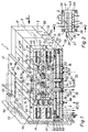
- valve assembly generally identified by reference number 1 includes a plurality, here: three pieces, of valve units 2, with which the distribution of one to operate is not fluid serving consumers, in particular Compressed air, can be controlled.
- Controllable consumers are, for example, working cylinders.
- the individual valve units 2 each have an elongated one Structure, their longitudinal axes are indicated at 3.
- valve units 2 are combined into a compact unit. To do this, they are on 4 sides in a row Side in such a way in a common alignment level 5 lined up that their longitudinal axes 3 parallel to the alignment level 5 and at the same time perpendicular extend to the row direction 4. Immediately successive Valve units 2 lie with their facing Surfaces firmly against each other. On the first and the last Valve unit 2 has an end plate 6, 6 ', between which the valve units 2 are firmly clamped together are. The cohesion is guaranteed in the row direction 4 extending tie rods 7, all valve units 2 pass through and on the connecting plates 6, 6 ' are anchored. This results in a block-like one Unit.
- Each valve unit 2 comprises a central base plate 8, the Plate level 12 perpendicular to the alignment level 5 stands and runs parallel to the associated longitudinal axis 3. It has an essentially rectangular cross section.
- a respective base plate 8 forms the housing of two in the Plate level 12 offset from each other and therefore arranged at right angles to the alignment level 5 one above the other Main valves 13, 14.
- Each of these main valves 13, 14 includes a substantially cylindrical in the embodiment Slider receptacle 15, which is parallel to the longitudinal axis 3 is aligned. In this way, there are 8 per base plate superimposed and parallel slide receptacles 15 provided, in each of which is only a dot-dash line indicated valve slide is located.
- the valve slide 16 is longitudinally movable in the slide holder 15 added and can therefore have different switching positions take in. These switch positions are under Mediation of electrically operated actuators 17, 17 'given as required, the two each other opposite end faces 18 one respective base plate 8 are releasably attached. You control the supply of an actuating fluid in a manner known per se, here: compressed air, to the opposite End faces of the valve slide 16 to act on them and thereby shift in one direction or the other.
- Each base plate 8 is traversed by a plurality of valve channels 19.
- valve channels 19 are, for example, a feed channel 22 and two ventilation channels 23 which the base plate 8th across, i.e. enforce parallel to row direction 4, see above that they are each on the front surface pointing in the row direction 4 24 and rear surface 25 of the base plate 8 open out.
- the Distribution of these valve channels 19, 22, 23 in the base plate 8 is identical among the individual valve units 2, so that the channel mouths of adjacent valve units 2 with each other aligned and 4 continuous common in the row direction Form channels.
- the rear end plate 6 is completely closed and thus forms a front end of the continuous Valve channels 19, 22, 23.
- the front end plate 6 provided with connection openings 26 which with the mentioned valve channels 19, 22, 23 are aligned.
- a corresponding supply line is indicated at 27.
- a silencer 28 can be attached to each a noise-reduced fluid flow guaranteed.
- the feed and ventilation channels 22, 23 expediently run in the vertical between the two slide holders 15 lying intermediate wall 31 of a respective base plate 8.
- the arrangement according to the example is such that the Feed channel 22 approximately in the middle with approximately the same distance to the two front side surfaces 18 runs and on both sides is flanked by a ventilation channel 23, which in the area between the feed channel 22 and a respective one end face 18.
- the first set of working channels 34 penetrate the located above the upper slide holder 15 upper Plate wall 35, on the one hand circumferentially in the upper Slider receptacle 15 opens and on the other hand on the outside upper side surface 37 of the base plate 8 opens out.
- it is under the lower slide holder 15 extending lower plate wall 36 of a respective one Base plate 8 from the second set of working channels 34 'vertically interspersed, on the one hand in the lower slide holder 15 open out and on the other hand to the lower side surface 38 of the base plate 8 open out.
- the working channels 34, 34 ' are in the area of their outer mouths provided with fastening threads that the immediate Allow connection of the pressure medium lines mentioned.
- a so-called BSP thread is introduced here.
- NTP thread is, for example, a so-called NTP thread.
- Around to provide these threads are those of a respective side surface 37, 38 associated mouths of the working channels 34, 34 'covered by a strip-shaped connecting plate 41, 41', which is provided with connection openings 42, their distribution matches that of the two rows of muzzle.
- connection openings 42 have the relevant fastening thread 43 on.
- each main valve 13, 14 is two Actuating devices 17; 17 'assigned.
- Actuating devices 17; 17 'assigned are the on a common outer surface 18 seated actuators 17, 17 'expediently in an actuating unit 44 summarized so that a uniform assembly and Disassembly on the base plate 8 is possible.
- the armature 48 runs parallel to the longitudinal axis 3 and is linear by excitation of the coil 47 movable, forming a valve member that cooperate with an opposite valve seat 49 the supply and / or discharge of the actuating fluid into an end face End region of a slide holder 15 controls.
- a respective one Actuating device 17, 17 ' is thus present as a solenoid valve trained, the valve seat 49, however, not is an immediate part of the actuating unit 44, but is formed on an intermediate plate 52 which between the actuating unit 44 and the associated end face Side surfaces 18 of the base plate 8 sits.
- the actuating fluid controlled by the actuators 17, 17 ' can be branched from the feed channel 22 or via separate pilot feed channels are supplied.
- the valve arrangement 1 can be laterally advantageously set on any support wall 53 so that it protrudes from it and its top and bottom are freely accessible is. This facilitates the required fluidic and electrical connections.
- a fastening plate 54 is provided for fastening, on a side face of the row of valve units 2 is fixed and with the help of fastening screws 56 or other fasteners on the supporting wall 53 is releasably fixable. Your attachment to the valve assembly expediently takes place via the two ends Connection plates 6,6 'with which the mounting plate 54 screwed in a manner not shown can.
- the mounting plate 54 according to the example is designed that even in the mounted state on the support wall 53 in the vertical direction the valve assembly 1 through conduit 57 is present, which enables that of the upper working channels 34 outgoing pressure medium lines protected downwards respectively.
- valve arrangement 1 has in addition to the advantageous embodiment the valve units 2 the further advantage of a special favorable arrangement of an electrical control unit 58 for the actuators 17, 17 '. This sits completely below the row of valve units 2 in the neighborhood the lower side surfaces 38 of the base plates 8.
- the electrical control unit 58 is in one from below 2 protective housings attached to the series of valve units 59 housed. Its front and back surfaces as well as the the two side faces close with the corresponding oriented outer surfaces of the valve units 2 or End plates 6, 6 'essentially flush, so that a Clear, compact block-like unit is available.
- the exemplary electrical control unit comprises a first printed circuit board aligned parallel to the alignment level 5 62, which with a variety of upward electrical connection contacts 63 is equipped.
- the first PCB 62 is attached to the valve unit 2 from below, their electrical connection contacts 63 simultaneously with complementary additional electrical connection contacts 64 can be contacted at the bottom of the actuators 44 are provided and with the actuators 17, 17 'are connected.
- the actuation units 44 can have a design that the corresponds to that described in DE 43 09 659 A1.
- Conductors not shown, provide a connection between the plate-side electrical connection contacts 63 and one also provided on the first circuit board 62 first multipole connector 65 forth. This in turn is in detachable electrical connection with a complementary second multipole connector 66 one second circuit board 61, which is parallel and spaced below the first circuit board 62 is arranged.
- This is with an only schematically indicated electronic Control device 67 equipped, which is made on the circuit board arranged electronic components. It is a programmable logic controller (SPS) trained, which can be moved down as needed outgoing connector 68 can be programmed.
- SPS programmable logic controller
- the first circuit board 62 acts as a distribution board for electrical actuation signals that the of the electronic control device 67 received control signals as instructed to the relevant electronic connection contacts 64 or the associated actuating devices 17, 17 'forwards.
- a higher-level connector can also be used external control device can be connected.
- connector 68 or a other suitable connectors a connection option to create for a fieldbus, especially as a two-wire bus is carried out and in serial transmission technology Signals coming from one on the second circuit board 61 installed fieldbus communication unit 69 received, decrypted and forwarded to the actuation units 44 become.
- the fieldbuses that can be connected are, for example a so-called ASI bus or PROFI bus.
- the second printed circuit board 61 additionally via electrical inputs 69, via the sensor signals can be fed by the electronic Control device 67 are processed.
- a diagnostic function can also be carried out via the electrical control unit run with the intermediation of pressure sensors is working.
- the pressure sensors can be connected to the working channels 34, 34 'to be connected to when certain Press to generate a reusable signal.
- a side housing wall 72 of the protective housing 59 which points away from the support wall 53, with a plurality of optical display elements 73, the on the electrical control unit 58 are connected and for example the respective switching status of the individual Main valves and, for example, the respective diagnostic status can display.
- the electrical control unit 58 also arranged at the top of the row of valve units 2 can be.
- the exemplary embodiment has the Advantage that both the pneumatic and the electrical Connections brought up to the valve assembly 1 from below can be.
- the advantageous arrangement of the electronic control unit 58 above and preferably below the row of valve units can also be achieved if a respective base plate only as a housing for a single one Main valve is equipped, with a corresponding one reduced number of actuators (17, 17 ') can be used.
Applications Claiming Priority (3)
| Application Number | Priority Date | Filing Date | Title |
|---|---|---|---|
| DE19526459 | 1995-07-20 | ||
| DE19526459A DE19526459A1 (de) | 1995-07-20 | 1995-07-20 | Ventilanordnung |
| EP96108698A EP0754866B1 (fr) | 1995-07-20 | 1996-05-31 | Arrangement de soupape |
Related Parent Applications (1)
| Application Number | Title | Priority Date | Filing Date |
|---|---|---|---|
| EP96108698A Division EP0754866B1 (fr) | 1995-07-20 | 1996-05-31 | Arrangement de soupape |
Publications (3)
| Publication Number | Publication Date |
|---|---|
| EP1013940A2 true EP1013940A2 (fr) | 2000-06-28 |
| EP1013940A3 EP1013940A3 (fr) | 2001-10-10 |
| EP1013940B1 EP1013940B1 (fr) | 2003-10-22 |
Family
ID=7767306
Family Applications (2)
| Application Number | Title | Priority Date | Filing Date |
|---|---|---|---|
| EP00108206A Expired - Lifetime EP1013940B1 (fr) | 1995-07-20 | 1996-05-31 | Arrangement de soupape |
| EP96108698A Expired - Lifetime EP0754866B1 (fr) | 1995-07-20 | 1996-05-31 | Arrangement de soupape |
Family Applications After (1)
| Application Number | Title | Priority Date | Filing Date |
|---|---|---|---|
| EP96108698A Expired - Lifetime EP0754866B1 (fr) | 1995-07-20 | 1996-05-31 | Arrangement de soupape |
Country Status (5)
| Country | Link |
|---|---|
| US (1) | US5765589A (fr) |
| EP (2) | EP1013940B1 (fr) |
| KR (1) | KR100194828B1 (fr) |
| DE (3) | DE19526459A1 (fr) |
| TW (1) | TW304223B (fr) |
Families Citing this family (22)
| Publication number | Priority date | Publication date | Assignee | Title |
|---|---|---|---|---|
| DE19840597A1 (de) | 1998-09-05 | 2000-03-16 | Festo Ag & Co | Ventilanordnung mit mindestens einer aus mehreren elektrisch betätigbaren Ventilen bestehenden Ventileinheit |
| DE19840596C1 (de) | 1998-09-05 | 1999-08-05 | Festo Ag & Co | Ventilanordnung mit mindestens einer aus mehreren elektrisch betätigbaren Ventilen bestehenden Ventileinheit |
| DE19942508A1 (de) | 1999-09-07 | 2001-03-15 | Festo Ag & Co | Verfahren und Vorrichtung zur Übertragung von Steuer- und/oder Sensorsignalen |
| DE19942509A1 (de) | 1999-09-07 | 2001-04-05 | Festo Ag & Co | Verfahren und Vorrichtung zur Versorgung von elektrischen Verbrauchern in oder an einer pneumatischen Vorrichtung mit elektrischer Versorgungsenergie |
| DE20006295U1 (de) * | 2000-04-06 | 2000-07-20 | Festo Ag & Co | Ventilanordnung |
| DE10048049A1 (de) * | 2000-09-28 | 2002-05-02 | Festo Ag & Co | Fluidtechnische Einrichtung mit einer Diagnoseeinrichtung |
| KR20020088241A (ko) * | 2001-05-18 | 2002-11-27 | 한명완 | 무수(Anhydrous) 방향족 슬폰산의 연속 제조방법 |
| DE10222890B4 (de) * | 2002-05-23 | 2004-06-17 | Bosch Rexroth Ag | Elektrische Einrichtung für die Ansteuerung eines Mehrwegeventils mit einer Verschleißzustandserkennung |
| US7036522B2 (en) * | 2003-08-19 | 2006-05-02 | Mac Valves, Inc. | Solenoid actuated pneumatic valve with an integrated pass-through and a quick mount body |
| DE102004009771A1 (de) * | 2004-02-28 | 2005-09-15 | Rexroth Mecman Gmbh | Ventileinheit mit wahlweise über eine serielle oder parallele Steuersignalübertragung ansteuerbaren Mehrwegeventilen |
| EP1965084B1 (fr) | 2007-02-28 | 2012-11-21 | FESTO AG & Co. KG | Appareil de la technologie de fluides muni d'une communication sans fil |
| US7753740B2 (en) * | 2007-07-20 | 2010-07-13 | Numatics, Incorporated | Modular electrical bus system |
| US8074680B2 (en) * | 2008-03-28 | 2011-12-13 | Numatics, Incorporated | Modular electrical bus system with built in ground circuit |
| US8302627B2 (en) | 2008-06-02 | 2012-11-06 | Eaton Corporation | Hydraulic system |
| US8464754B2 (en) | 2008-06-02 | 2013-06-18 | Eaton Corporation | Valve manifold |
| US11420417B2 (en) | 2013-03-15 | 2022-08-23 | Scorrboard Llc | Methods and apparatus for producing scored mediums, and articles and compositions resulting therefrom |
| KR102169315B1 (ko) * | 2014-05-23 | 2020-10-23 | 두산인프라코어 주식회사 | 건설기계를 위한 파일럿 신호용 블록 조립체 및 이를 갖는 컨트롤 밸브 조립체 |
| US10328654B2 (en) | 2016-04-20 | 2019-06-25 | Scorrboard, Llc | System and method for producing a multi-layered board having a medium with improved structure |
| US10800133B2 (en) | 2016-04-20 | 2020-10-13 | Scorrboard, Llc | System and method for producing a facing for a board product with strategically placed scores |
| US11027515B2 (en) | 2016-04-20 | 2021-06-08 | Scorrboard Llc | System and method for producing multi-layered board having at least three mediums with at least two mediums being different |
| DE102016120029A1 (de) * | 2016-10-20 | 2018-04-26 | Bürkert Werke GmbH | Ventilanordnung |
| DE102016120027A1 (de) | 2016-10-20 | 2018-04-26 | Bürkert Werke GmbH | Ventilanordnung |
Citations (3)
| Publication number | Priority date | Publication date | Assignee | Title |
|---|---|---|---|---|
| DE4143274A1 (de) | 1991-12-27 | 1993-08-05 | Mannesmann Ag | Ventilbaugruppe in modulbauweise |
| FR2693516A1 (fr) | 1992-07-10 | 1994-01-14 | Festo Kg | Dispositif à soupape. |
| DE4309695A1 (de) | 1993-03-25 | 1994-09-29 | Festo Kg | Steuereinrichtung für ein Mehrwegeventil |
Family Cites Families (13)
| Publication number | Priority date | Publication date | Assignee | Title |
|---|---|---|---|---|
| US3464444A (en) * | 1968-11-29 | 1969-09-02 | Koehring Co | Pilot controllable valve mechanism |
| US4082108A (en) * | 1976-07-19 | 1978-04-04 | Maul Technology Corporation | Valve block |
| FR2540214B1 (fr) * | 1983-01-27 | 1986-03-14 | Rexroth Sigma | Perfectionnements apportes aux distributeurs de fluide |
| US4561463A (en) * | 1984-03-23 | 1985-12-31 | Koehring Company | Sectional valve having dual pressure relief |
| DE3427589A1 (de) * | 1984-07-26 | 1986-02-06 | Festo KG, 7300 Esslingen | Ventiltraeger |
| JPH0440053Y2 (fr) * | 1984-12-18 | 1992-09-18 | ||
| US4709724A (en) * | 1986-01-17 | 1987-12-01 | Commercial Shearing, Inc. | Fluid valve structures |
| JPH0627901Y2 (ja) * | 1987-07-03 | 1994-07-27 | 黒田精工株式会社 | 電磁弁装置 |
| DE3919413A1 (de) * | 1989-06-14 | 1990-12-20 | Bosch Gmbh Robert | Wegeventil fuer blockbauweise |
| DE4020024A1 (de) * | 1990-06-23 | 1992-01-02 | Bosch Gmbh Robert | Elektromagnetisch betaetigbares wegeventil |
| DE4137868C2 (de) * | 1991-11-11 | 1993-12-16 | Mannesmann Ag | Mehrwege-Schieberventil |
| DE4226539A1 (de) * | 1992-08-11 | 1994-02-17 | Bosch Gmbh Robert | Elektropneumatische Ventilbaugruppe |
| EP0628729B1 (fr) * | 1993-05-07 | 1998-09-02 | Smc Kabushiki Kaisha | Distributeur et ensemble de distributeurs |
-
1995
- 1995-07-20 DE DE19526459A patent/DE19526459A1/de not_active Withdrawn
-
1996
- 1996-05-31 DE DE59610791T patent/DE59610791D1/de not_active Expired - Lifetime
- 1996-05-31 DE DE59607401T patent/DE59607401D1/de not_active Expired - Lifetime
- 1996-05-31 EP EP00108206A patent/EP1013940B1/fr not_active Expired - Lifetime
- 1996-05-31 EP EP96108698A patent/EP0754866B1/fr not_active Expired - Lifetime
- 1996-06-13 TW TW085107095A patent/TW304223B/zh not_active IP Right Cessation
- 1996-07-03 US US08/675,347 patent/US5765589A/en not_active Expired - Fee Related
- 1996-07-05 KR KR1019960027244A patent/KR100194828B1/ko not_active IP Right Cessation
Patent Citations (3)
| Publication number | Priority date | Publication date | Assignee | Title |
|---|---|---|---|---|
| DE4143274A1 (de) | 1991-12-27 | 1993-08-05 | Mannesmann Ag | Ventilbaugruppe in modulbauweise |
| FR2693516A1 (fr) | 1992-07-10 | 1994-01-14 | Festo Kg | Dispositif à soupape. |
| DE4309695A1 (de) | 1993-03-25 | 1994-09-29 | Festo Kg | Steuereinrichtung für ein Mehrwegeventil |
Also Published As
| Publication number | Publication date |
|---|---|
| DE19526459A1 (de) | 1997-01-23 |
| DE59607401D1 (de) | 2001-09-06 |
| TW304223B (fr) | 1997-05-01 |
| US5765589A (en) | 1998-06-16 |
| EP1013940B1 (fr) | 2003-10-22 |
| EP0754866B1 (fr) | 2001-08-01 |
| EP0754866A2 (fr) | 1997-01-22 |
| EP0754866A3 (fr) | 1998-07-15 |
| DE59610791D1 (de) | 2003-11-27 |
| EP1013940A3 (fr) | 2001-10-10 |
| KR100194828B1 (ko) | 1999-06-15 |
| KR970007021A (ko) | 1997-02-21 |
Similar Documents
| Publication | Publication Date | Title |
|---|---|---|
| EP1013940B1 (fr) | Arrangement de soupape | |
| DE4004834C2 (de) | Ventilbaugruppe | |
| DE60301746T2 (de) | Pneumatikventilgruppe mit einfacher Installierung und einfacher Wartung | |
| DE4230414C2 (de) | Elektro-pneumatische Steuereinrichtung | |
| EP1710447B1 (fr) | Appareil de commande électro-fluidique | |
| EP1183472B1 (fr) | Module electronique destine notamment a une unite de commande equipee de soupapes | |
| WO1994004831A1 (fr) | Dispositif de commande electropneumatique | |
| DE10013192B4 (de) | Ventilanordnung | |
| WO1996019027A1 (fr) | Dispositif de commande, notamment de commande de soupapes | |
| EP0968372A1 (fr) | Base de montage en forme de plaque | |
| DE3427589A1 (de) | Ventiltraeger | |
| EP0740082B1 (fr) | Dispositif électrique modulaire pour un assemblage de bloc de vannes | |
| EP0629783B1 (fr) | ContrÔle combiné de valves pneumatiques et hydrauliques | |
| EP3296602B1 (fr) | Dispositif de distribution de fluide | |
| EP0621407B1 (fr) | Ensemble valve | |
| DE10153545B4 (de) | Fluidkraft-Verriegelungssystem und Verfahren zum Verriegeln von Fluidkraftsignalen | |
| DE10203792B4 (de) | Pneumatische Ventileinheit mit einer parallelen elektrischen Verdrahtung | |
| DE10213397B4 (de) | Ventilanordnung | |
| EP1515050A2 (fr) | Dispositif de commande | |
| EP1251283B1 (fr) | Kit pour fabriquer un dispositif de contrôle fluidique | |
| EP1284371B1 (fr) | Assemblage de valves sous forme de matrice | |
| EP1283369B1 (fr) | Assemblage de valves de forme plate | |
| AT405464B (de) | Pneumatische betätigungsanordnung | |
| EP2106506A1 (fr) | Appareil à soupape doté d'un dispositif opto-électrique d'affichage d'état |
Legal Events
| Date | Code | Title | Description |
|---|---|---|---|
| PUAI | Public reference made under article 153(3) epc to a published international application that has entered the european phase |
Free format text: ORIGINAL CODE: 0009012 |
|
| 17P | Request for examination filed |
Effective date: 20000414 |
|
| AC | Divisional application: reference to earlier application |
Ref document number: 754866 Country of ref document: EP |
|
| AK | Designated contracting states |
Kind code of ref document: A2 Designated state(s): DE FR IT NL |
|
| RIN1 | Information on inventor provided before grant (corrected) |
Inventor name: BEYER, DIETER Inventor name: STOLL, KURT, DR. |
|
| PUAL | Search report despatched |
Free format text: ORIGINAL CODE: 0009013 |
|
| AK | Designated contracting states |
Kind code of ref document: A3 Designated state(s): DE FR IT NL |
|
| AKX | Designation fees paid |
Free format text: DE FR IT NL |
|
| GRAH | Despatch of communication of intention to grant a patent |
Free format text: ORIGINAL CODE: EPIDOS IGRA |
|
| GRAS | Grant fee paid |
Free format text: ORIGINAL CODE: EPIDOSNIGR3 |
|
| GRAA | (expected) grant |
Free format text: ORIGINAL CODE: 0009210 |
|
| AC | Divisional application: reference to earlier application |
Ref document number: 0754866 Country of ref document: EP Kind code of ref document: P |
|
| AK | Designated contracting states |
Kind code of ref document: B1 Designated state(s): DE FR IT NL |
|
| REF | Corresponds to: |
Ref document number: 59610791 Country of ref document: DE Date of ref document: 20031127 Kind code of ref document: P |
|
| ET | Fr: translation filed | ||
| PLBE | No opposition filed within time limit |
Free format text: ORIGINAL CODE: 0009261 |
|
| STAA | Information on the status of an ep patent application or granted ep patent |
Free format text: STATUS: NO OPPOSITION FILED WITHIN TIME LIMIT |
|
| 26N | No opposition filed |
Effective date: 20040723 |
|
| PGFP | Annual fee paid to national office [announced via postgrant information from national office to epo] |
Ref country code: NL Payment date: 20080516 Year of fee payment: 13 |
|
| NLV4 | Nl: lapsed or anulled due to non-payment of the annual fee |
Effective date: 20091201 |
|
| PG25 | Lapsed in a contracting state [announced via postgrant information from national office to epo] |
Ref country code: NL Free format text: LAPSE BECAUSE OF NON-PAYMENT OF DUE FEES Effective date: 20091201 |
|
| PGFP | Annual fee paid to national office [announced via postgrant information from national office to epo] |
Ref country code: IT Payment date: 20110503 Year of fee payment: 16 |
|
| PGFP | Annual fee paid to national office [announced via postgrant information from national office to epo] |
Ref country code: DE Payment date: 20120420 Year of fee payment: 17 |
|
| PGFP | Annual fee paid to national office [announced via postgrant information from national office to epo] |
Ref country code: FR Payment date: 20120608 Year of fee payment: 17 |
|
| PG25 | Lapsed in a contracting state [announced via postgrant information from national office to epo] |
Ref country code: IT Free format text: LAPSE BECAUSE OF NON-PAYMENT OF DUE FEES Effective date: 20120531 |
|
| PG25 | Lapsed in a contracting state [announced via postgrant information from national office to epo] |
Ref country code: DE Free format text: LAPSE BECAUSE OF NON-PAYMENT OF DUE FEES Effective date: 20131203 |
|
| REG | Reference to a national code |
Ref country code: DE Ref legal event code: R119 Ref document number: 59610791 Country of ref document: DE Effective date: 20131203 |
|
| REG | Reference to a national code |
Ref country code: FR Ref legal event code: ST Effective date: 20140131 |
|
| PG25 | Lapsed in a contracting state [announced via postgrant information from national office to epo] |
Ref country code: FR Free format text: LAPSE BECAUSE OF NON-PAYMENT OF DUE FEES Effective date: 20130531 |