EP3296602B1 - Dispositif de distribution de fluide - Google Patents
Dispositif de distribution de fluide Download PDFInfo
- Publication number
- EP3296602B1 EP3296602B1 EP17185573.7A EP17185573A EP3296602B1 EP 3296602 B1 EP3296602 B1 EP 3296602B1 EP 17185573 A EP17185573 A EP 17185573A EP 3296602 B1 EP3296602 B1 EP 3296602B1
- Authority
- EP
- European Patent Office
- Prior art keywords
- valve
- mounting
- hybrid
- valve support
- module
- Prior art date
- Legal status (The legal status is an assumption and is not a legal conclusion. Google has not performed a legal analysis and makes no representation as to the accuracy of the status listed.)
- Active
Links
- 239000012530 fluid Substances 0.000 title claims description 72
- 238000010397 one-hybrid screening Methods 0.000 claims description 9
- 238000010276 construction Methods 0.000 claims description 2
- 238000010396 two-hybrid screening Methods 0.000 description 10
- 230000008054 signal transmission Effects 0.000 description 8
- 238000004891 communication Methods 0.000 description 2
- 230000000295 complement effect Effects 0.000 description 2
- 238000005516 engineering process Methods 0.000 description 2
- 239000000758 substrate Substances 0.000 description 2
- 230000006978 adaptation Effects 0.000 description 1
- 230000001419 dependent effect Effects 0.000 description 1
- 238000011161 development Methods 0.000 description 1
- 230000018109 developmental process Effects 0.000 description 1
- 238000009434 installation Methods 0.000 description 1
- 238000007789 sealing Methods 0.000 description 1
Images

Classifications
-
- F—MECHANICAL ENGINEERING; LIGHTING; HEATING; WEAPONS; BLASTING
- F16—ENGINEERING ELEMENTS AND UNITS; GENERAL MEASURES FOR PRODUCING AND MAINTAINING EFFECTIVE FUNCTIONING OF MACHINES OR INSTALLATIONS; THERMAL INSULATION IN GENERAL
- F16K—VALVES; TAPS; COCKS; ACTUATING-FLOATS; DEVICES FOR VENTING OR AERATING
- F16K27/00—Construction of housing; Use of materials therefor
- F16K27/003—Housing formed from a plurality of the same valve elements
-
- F—MECHANICAL ENGINEERING; LIGHTING; HEATING; WEAPONS; BLASTING
- F15—FLUID-PRESSURE ACTUATORS; HYDRAULICS OR PNEUMATICS IN GENERAL
- F15B—SYSTEMS ACTING BY MEANS OF FLUIDS IN GENERAL; FLUID-PRESSURE ACTUATORS, e.g. SERVOMOTORS; DETAILS OF FLUID-PRESSURE SYSTEMS, NOT OTHERWISE PROVIDED FOR
- F15B13/00—Details of servomotor systems ; Valves for servomotor systems
- F15B13/02—Fluid distribution or supply devices characterised by their adaptation to the control of servomotors
- F15B13/06—Fluid distribution or supply devices characterised by their adaptation to the control of servomotors for use with two or more servomotors
- F15B13/08—Assemblies of units, each for the control of a single servomotor only
- F15B13/0803—Modular units
- F15B13/0807—Manifolds
- F15B13/0817—Multiblock manifolds
-
- F—MECHANICAL ENGINEERING; LIGHTING; HEATING; WEAPONS; BLASTING
- F15—FLUID-PRESSURE ACTUATORS; HYDRAULICS OR PNEUMATICS IN GENERAL
- F15B—SYSTEMS ACTING BY MEANS OF FLUIDS IN GENERAL; FLUID-PRESSURE ACTUATORS, e.g. SERVOMOTORS; DETAILS OF FLUID-PRESSURE SYSTEMS, NOT OTHERWISE PROVIDED FOR
- F15B13/00—Details of servomotor systems ; Valves for servomotor systems
- F15B13/02—Fluid distribution or supply devices characterised by their adaptation to the control of servomotors
- F15B13/06—Fluid distribution or supply devices characterised by their adaptation to the control of servomotors for use with two or more servomotors
- F15B13/08—Assemblies of units, each for the control of a single servomotor only
- F15B13/0803—Modular units
- F15B13/0871—Channels for fluid
-
- F—MECHANICAL ENGINEERING; LIGHTING; HEATING; WEAPONS; BLASTING
- F15—FLUID-PRESSURE ACTUATORS; HYDRAULICS OR PNEUMATICS IN GENERAL
- F15B—SYSTEMS ACTING BY MEANS OF FLUIDS IN GENERAL; FLUID-PRESSURE ACTUATORS, e.g. SERVOMOTORS; DETAILS OF FLUID-PRESSURE SYSTEMS, NOT OTHERWISE PROVIDED FOR
- F15B13/00—Details of servomotor systems ; Valves for servomotor systems
- F15B13/02—Fluid distribution or supply devices characterised by their adaptation to the control of servomotors
- F15B13/06—Fluid distribution or supply devices characterised by their adaptation to the control of servomotors for use with two or more servomotors
- F15B13/08—Assemblies of units, each for the control of a single servomotor only
- F15B13/0803—Modular units
- F15B13/0878—Assembly of modular units
- F15B13/0896—Assembly of modular units using different types or sizes of valves
Definitions
- the invention relates to a fluid distribution device, with a modular valve carrier, which is penetrated by a fluid-flow through valve carrier channel system and has a plurality of valve carrier modules which are lined up in a Aukahungscardi and each have a carrier body having an assembly area, the at least one Defined loading station for placement with a valve, wherein the valve carrier channel system opens with each provided for connection to a valve channel openings at each placement space for assembly area and a plurality of the valve carrier axially traversing through channels, each of which empties via a channel mouth at each placement of each carrier body wherein the channel mouths are distributed at each placement place distributed to form a mouth pattern.
- EP 2 412 985 A2 discloses such a fluid manifold assembly comprising a module assembly composed of a plurality of manifold modules juxtaposed in a line-up direction and interconnected by threaded connections, wherein a first manifold module is bolted to a second manifold module by means of an adapter element mounted in juxtaposed condition of the two manifold modules a recess of the second distributor module dips and which can be clamped by means of a second distributor module passing through the connecting screw with the second distributor module.
- the distributor modules each have a placement area, which defines either only one placement space or two juxtaposed placement locations, the distribution modules can be equipped at each placement with a serving to control fluid flows valve.
- a fluid distributor arrangement which has a plurality of valve carrier modules arranged on one another, wherein a valve carrier module is designed to be equipped with a single valve and a further valve carrier module is to be equipped with two valves.
- the US Pat. No. 8,307,854 B1 describes a fluid distribution device having a plurality of juxtaposed fluid flow substrates interspersed with fluid channels.
- Each fluid flow substrate has a component mounting surface on which there are a plurality of channel openings of the fluid channels and which is equipped with at least one fluid processing component, for example a valve.
- the invention is based on the object to take measures that allow a more flexible use of the fluid distribution device.
- At least one valve support module is a hybrid valve support module
- the carrier body forms a hybrid carrier body
- the placement surface defines two arranged in the line-up juxtaposed placement places in the muzzle pattern of them arranged channel openings differ from each other.
- At least one valve support module is designed as a hybrid valve support module, whose carrier body referred to as a hybrid body has a placement surface, which can be equipped with two, for example, in their size differing valves that can control, for example, different sized fluid flow rates, preferably for Control of connected to the fluid distribution device consumers.
- the possibility of equipping the hybrid valve carrier module with differently designed valves is based on the fact that the mouth patterns of the channel mouths arranged at the two placement locations of the hybrid carrier body differ from one another.
- the valves each have a mounting surface provided for mounting on a carrier body via a mouth pattern formed by channel mouths of their valve channels, wherein these mouth patterns are different in the case of differently designed valves and, in particular, differently dimensioned valves.
- two differently shaped valves can be mounted without using an adapter on one and the same valve carrier module called a hybrid valve carrier module.
- a larger valve can flow through a larger valve mounted on the hybrid carrier body than through a smaller valve mounted on the same hybrid carrier body, as a result of which connected consumers with fluid flows of different sizes can be supplied as needed via one and the same valve carrier.
- the fluid distribution device is therefore very flexible overall.
- valve carrier channel system has a plurality of passage channels axially passing through the valve carrier, each opening out via a channel mouth at each placement space of each carrier body. This ensures that each valve arranged on a valve module valve can be centrally supplied with fluid via the channel mouths of a loading station and, if necessary, a collected fluid removal is possible.
- the hybrid carrier body of each hybrid valve carrier module has an assembly area which defines two placement locations adjacent to one another in the line-up direction of the valve carrier modules, wherein the one placement space has, for example, a plurality of equidistant channel openings which form a first mouth pattern.
- the second placement space has an equal number of channel mouths that form a second orifice pattern different from the first orifice pattern, for example, spaced apart by half the distance from the channel orifices of the first orifice pattern. Therefore, for example, a valve of a larger series can be mounted on the mouth pattern of the first stocking place than on the mouth pattern of the second stocking place.
- One or more other valve support modules can be connected to the at least one hybrid valve support module in the line-up direction so that the valve support of the fluid distribution device is more or less long in the line-up direction and can be equipped with a different number of valves. Due to the modular structure of the valve carrier, the length of the valve carrier can be selected as required very variable.
- the valve carrier passage system preferably passes through all of the valve carrier modules interconnected to form the valve carrier, i. both the at least one hybrid valve carrier module and any further, not in hybrid technology running valve carrier modules, which have only a single placement space or more about a same mouth pattern of channel mouths equipped placement stations.
- Such valve carrier modules not embodied in the hybrid technology according to the invention are also referred to below as standard valve carrier modules.
- the valve carrier channel system opens at each placement of the valve support modules.
- the channel mouths are arranged at each placement space spaced from each other in a certain pattern referred to as the mouth pattern.
- a fluid which is preferably compressed air or also a pressure fluid, flows through the valve carrier channel system and the valves mounted on the valve carrier.
- the channel mouths of the mouth patterns of the two placement locations of the hybrid carrier body differ in their relative positions and / or in their cross-sectional areas, such that the two placement locations can be equipped with different valves.
- Valves of different sizes differ from each other in particular by their internal valve channel cross-sections and thus by the fluid volume flows, they can control and guide them to a consumer and, as a result, through the mouth patterns of the channel mouths present on their mounting surfaces, whose relative positions can be different from each other.
- the need-based supply of the valves with fluid is preferably achieved by the cross-sectional areas of the channel mouths of the placement slots of the hybrid valve carrier are adjusted accordingly.
- the cross-sectional areas of the channel mouths belonging to a mouth pattern of the one loading place are relatively large, so that a relatively large fluid volume flow can flow over the cross-sectional areas to a large valve, while the cross-sectional areas of the channel mouths of the mouth pattern of the other loading place are relatively small, so that a relative small fluid flow over the cross-sectional areas can flow to a relatively small valve.
- valves As a result of the cross-sectional areas of the channel openings of the outlet patterns, more or less fluid can flow, so that it is determined by adjusting the cross-sectional areas of the fluid volume flow that can be controlled by the valves.
- the difference between the relative positions of the channel mouths of a muzzle pattern of the hybrid valve carrier from the channel mouths of the other muzzle pattern allows the installation of valves that differ, for example, in their size or in their design, for example slide valve or poppet valve.
- the center distance between the channel mouths belonging to the same orifice pattern of one fitting station of the hybrid valve carrier module is greater than the center distance between the channel mouths belonging to the same mouth pattern of the other mounting position of the hybrid valve carrier module.
- the center distance designates the distance measured between a geometric center of a channel mouth and a geometric center of another channel mouth, wherein the geometric center preferably occupies the position of the geometric center of the respective channel mouth when the channel mouth is circular.
- the mouth pattern of the channel mouths of a placement space of the hybrid carrier body coincides with at least one mouth pattern of the channel mouths of the carrier body of at least one further valve carrier module arranged in the line-up direction on the hybrid valve carrier module, the match being expediently given with all mouth patterns of all other valve carrier modules.
- This ensures that at least one valve is mounted or mounted on the hybrid valve carrier module whose design and / or size matches the valves mounted on the other valve carrier modules valves.
- all mounted valves with the exception of one of the two valves arranged on the hybrid valve module, match in their size, so that the valve carrier of the fluid distribution device has exactly one valve that in its design and / or size of the remaining valves mounted on the valve carrier differs.
- the support body of at least one valve support module has two mounting positions arranged next to one another in the line-up direction and matching their muzzle patterns. This ensures that two valves of the same type and / or size are mounted or mounted on a valve support module, so that the valve support can be extended by the arrangement of such a valve support module by two identical valves, which makes the structure of the fluid distribution device very fast and easy.
- a valve support module should also be referred to as a standard valve support module for better distinction.
- the channel mouths of the mouth patterns of all placement locations are arranged symmetrically, in particular mirror-symmetrically, on both sides of a reference plane which runs along the line-up direction and along a vertical axis of the valve carrier oriented orthogonally to the assembly surfaces.
- a reference plane which runs along the line-up direction and along a vertical axis of the valve carrier oriented orthogonally to the assembly surfaces.
- each placement space of the carrier body has an electromechanical interface device which is provided for connection to an electrical actuating device of a valve mounted or mountable on the associated mounting station.
- the electromechanical interface devices of the two mounting locations of the hybrid carrier body preferably have a different distance to a reference plane passing through the mouth patterns of these two mounting stations, along the alignment direction and along an orthogonal direction to the mounting surfaces oriented vertical axis of the valve carrier runs.
- the electromechanical interface devices of the placement stations allow an electrical connection between on the one hand an actuator of a valve arranged on a placement place and on the other hand preferably arranged on the valve carrier electronic control device, which in turn communicates with a higher-level control unit, for example.
- each individual valve via its actuating device for a purposeful influencing of the fluid flowing through the fluid distribution device.
- the electrical communication is advantageously carried out via a arranged in the interior of the valve carrier signal transmission line, for example in the form of a board assembly or a flexible cable harness.
- each valve carrier module has at least one individual working channel, which opens on the one hand at the associated placement space of the respective support body to the mounting surface and on the other hand to a remote from the mounting surface of the support body outer surface.
- Each working channel forms at a loading place and the outer surface of the support body from a channel mouth.
- a mounted on the mounting position of the support body valve has at its mounting surface on a channel mouth, which is aligned with the channel mouth of the working channel, so that fluid can flow from the valve to the working channel and back.
- a consumer via a fluid line can be connected.
- the valve carrier has exactly one hybrid valve carrier module, which is the row of valve carrier modules concluding valve support module, wherein expediently a mouth pattern of the channel mouths of the hybrid valve support module and all other orifice patterns of the other valve support modules are identical to each other.
- a final valve support module is arranged, in which it is a hybrid valve carrier module. Due to the arrangement of the hybrid valve carrier module at one end of the valve carrier, in particular the last assembly area of the hybrid valve carrier, adjacent to the only on one side of another assembly area, relatively easy to reach for assembly purposes, so that the assembly of a valve on this assembly area in particular then it is particularly fast possible if it is a relatively small valve.
- a special valve which is designed to control a particularly small fluid volume flow can be mounted on the assembly space of the hybrid valve support module, which has the orifice pattern deviating from the other orifice patterns of the valve support modules.
- valve of the fluid distribution device for influencing the fluid flow of the fluid flowing through the valve-channel system fluid is mounted or mounted on the placement areas of the mounting surfaces of the carrier body.
- a cover plate is attached to a placement place, which closes the channel mouths of the placement space fluid-tight.
- valves in each case a plurality of valve channels are formed, which open to a mounted on a mounting space of a support body mounting surface of the valve via a mouth forming channel openings, the mouth pattern of the channel mouths of the mounting surface the mouth pattern of the channel mouths of the respectively assigned placement space equivalent.
- At least one hybrid valve support module in the line-up direction is made narrower than the standard valve support modules which are not designed as a hybrid valve support module.
- the fluid distribution device can be realized with a short overall length.
- At least two mounting holes for releasably mounting a valve serving mounting holes are formed at each placement space of the mounting surface of all valve carrier modules, wherein the mounting holes of a mounting slot of the hybrid valve carrier module in their measured in the alignment direction center distance and / or in differentiate their hole diameter from the mounting holes of the other mounting location of the hybrid valve support module.
- the mounting holes of the placement of the not designed as a hybrid valve carrier module standard valve support modules in their center distance and hole diameter match the mounting holes of one of the two placement locations of the hybrid valve support module.
- each valve provided for mounting on the mounting locations of the valve carrier modules also has mounting holes.
- the mounting holes of a loading place and the mounting holes of the valves each form the same hole patterns, so that the mounting holes with each other and the mounting holes have the same distance from each other.
- the hole patterns of the mounting holes of the valve are aligned with each other, so that fasteners can be inserted through the mounting holes and the mounting holes for fastening the valve.
- the fastening means may be formed as fastening screws.
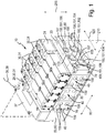
- an overall fluid distribution device 10 which serves to distribute fluid to consumers, which are connected to the fluid distribution device 10.
- the consumers are preferably pneumatic devices or Hydraulic devices, in particular fluid-operated drives.
- the fluid distribution device 10 comprises a valve carrier 20, on which valves 30 are mounted or mounted, with which the fluid distribution can be controlled to the connected to the valve carrier 20 consumers.
- the valve carrier 20 is a modular assembly, which is composed at least of valve carrier modules 40 and preferably also of end modules 50.
- the valve support modules 40 and the termination modules 50 are disposed in a line-up direction 60 and interconnected via module fasteners 70 to form a rigid valve support 20.
- the valve carrier 20 comprises three valve carrier modules 40 which are arranged in the arrangement direction 60 against one another and two closure modules 50, which line up in the line-up direction 60 from both sides to the valve carrier modules 40.
- the two termination modules 50 are designed, on the one hand, as a connection module 80 and, on the other hand, as a control module 90, which are each connected to the valve support modules 40 via module attachment means 70.
- the module fastening means 70 are, for example, fastening screws.
- the valve carrier modules 40 lined up in the line-up direction 60 each have a carrier body 41, which is preferably formed in one piece.
- the carrier body 41 preferably has two attachment surfaces 100, which are arranged in the alignment direction 60 on mutually opposite sides of the carrier body 41, wherein the attachment surfaces 100 are preferably aligned parallel to each other.
- the carrier body 41 of the valve carrier modules 40 can be connected to each other via the mounting surfaces 100 with the interposition of sealing means in the alignment direction 60 via the module mounting means 70.
- each carrier body 41 at one in the FIGS. 1 and 2 top side facing a loading surface 110, which preferably parallel to one of the Aukahungsplatz 60 and a direction perpendicular to the array direction 60 extending transverse direction 120 spanned first reference plane 130 runs.
- the first reference plane 130 is indicated by a dashed frame.
- the mounting surfaces 110 of the individual carrier bodies 41 preferably each have the same distance from the reference plane 130.
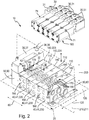
- the mounting surface 110 of the carrier body 41 of each valve carrier module 40 defines at least one loading station 140, which in the Figures 2 and 3 is indicated by a dash double dotted frame.
- a valve 30 may be mounted or mounted, for example, an electrically actuated pneumatic valve, which is preferably a multi-way valve designed as a slide valve.
- a valve carrier channel system 150 formed in the valve carrier 20 opens out via channel openings 160, wherein the channel openings 160 per placement place 140 define a pattern designated as a mouth pattern 170.
- the channel openings 160 present at the placement locations 140 are also referred to below as valve carrier channel openings 160.
- the mouth pattern 170 of the valve carrier channel openings 160 is, for example, by the relative distance of the valve carrier channel openings 160 with each other and / or characterized by differently sized cross-sectional areas of the valve carrier channel openings 160.
- a channel system is formed, which is not shown in more detail in the figures.
- This channel system opens out at a mounting surface 180 of a valve 30 via valve channel openings, which form a valve mouth pattern on the mounting surface 180. With the mounting surface 180 first, the valves 30 can be mounted or mounted on the placement sites 140.
- each valve 30 is configured to mate with the orifice pattern 170 of the valve carrier channel orifices 160 opening out at at least one of the placement locations 140 so that the valves 30 can be mounted to the placement locations 140 to form fluid connections and fluid over the Valve carrier channel openings 160 and the valve channel openings can flow.
- each valve carrier module 40 furthermore has at least one outer surface designated as a connection surface 190, which preferably runs parallel to a second reference plane 210 spanned by the alignment direction 60 and a vertical axis 200 perpendicular to the alignment direction 60 and the transverse direction 120.
- a connection surface 190 which preferably runs parallel to a second reference plane 210 spanned by the alignment direction 60 and a vertical axis 200 perpendicular to the alignment direction 60 and the transverse direction 120.
- all connecting surfaces 190 of the valve carrier 20 have the same distance from the second reference plane 210, so that the connecting surfaces 190 of all carrier bodies 41 form a single plane.
- the pad 190 could also be formed on the mounting surface 110 opposite underside of the carrier body 41.
- At least one individual working channel 159 of the valve carrier channel system 150 is formed in each carrier body 41 of the valve carrier 20, which opens on one side to at least one connection surface 190 of the carrier body 41 via a working channel opening and on the other hand via a mouth member 170 forming valve carrier channel mouth 160th opens at the placement space 140 of the respective carrier body 41.
- two individual working channels 159 emanate from each placement space 140. If the carrier body 41 according to the exemplary embodiment has two placement locations, four individual working channels 159 each open on the connection surface 190 of the carrier body 41 of the respective valve carrier module 40 via one working channel opening.
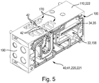
- the valve carrier channel system 150 which opens out at each placement space 140 of a carrier body 41 via the valve carrier channel openings 160, continues to open outwards at the connection module 80. There it defines connection openings 153, 155, 157, via which external pressure sources and / or pressure sinks can be connected, which are not shown in the figures, so that the valve carrier channel system 150 can be supplied with fluid and can be disposed of as fluid.
- the valve carrier channel system 150 includes, in addition to the individual working channels 159, at least one and preferably a plurality of through channels 151 passing through the valve carrier 20 in the array direction 60. Each of these through channels 151 opens out via one of the valve support channel openings 160 at each placement place 140.
- the through-channels 151 preferably contain a feed channel 152 passing through the valve carrier 20 longitudinally in the line-up direction 60. This opens on the one hand to the connection module 80 via a connection opening 153 forming a feed connection, via which it can be connected to an external pressure source, and on the other hand via a respective valve carrier channel mouth 160 at a placement place 140 of a carrier body 41.
- valve carrier channel system 150 also has two passage channels 151, each of which forms a discharge channel 154 which, on the one hand, opens out via a connection port 155 forming a discharge port and on the other hand, at each placement station 140 of a carrier body 41 via a respective valve carrier channel mouth 160 , About the discharge port is connected to a pressure sink, in particular to the atmosphere.
- the valve carrier channel system 150 optionally also has at least one passage 151 formed as a pilot passage 156.
- exactly two pilot passages 156 are present, which respectively open on the connection module 80 via a connection opening 157 forming a pilot port and on the other hand at each placement position 140 of a carrier body 41 via one of the valve carrier channel openings 160 open.
- all passage channels 151 of the valve carrier channel system 150 are composed of a plurality of through-channel sections 158, each of which the carrier body 41 of a Valve carrier module 40 from one acreage 100 through to the oppositely arranged other acreage 100 enforce.
- the passage channel sections 158 complement each other to the passageways 151th
- valve carrier channel openings 160 of each placement space are preferably distributed mirror-symmetrically about the second reference plane 210 in the transverse direction 120.
- Each valve support channel port 160 is arranged and configured to be aligned with a valve port of a valve 30 when the valve 30 is in the mounted state on the placement space 140 of the support body 41. It is thereby achieved that all the valve support channel openings 160 belonging to the same orifice pattern 170 of each fitting space 140 of each support body 41 coincide with the valve channel orifices of the valve orifice pattern of the valve 30 mounted on the assembly station 140, so that fluid is present between the valve support channel orifices 160 and the valve Channel mouths can flow over.
- each valve 30 has an electrical actuating device 31, by means of which it can be brought into different switching positions in which different valve channels of the valve 30 are in communication with different through-channels 151 and individual working channels 159 of the valve carrier channel system 150.
- the channels of the valve carrier channel system 150 which open out at the placement location 140 assigned to the respective valve 30 are connected to one another in different patterns.
- the electrical actuator 31 of each valve 30 is connected via an arranged at each placement space 140 of each carrier body 41 electromechanical interface device 32 with an electrical signal transmission line 34 in connection, which is arranged in a valve carrier 20 in the alignment direction 60 passing signal transmission channel 33.
- the signal transmission line 34 is composed of individual strand sections 35, which are assigned to each carrier body 41, wherein the individual strand sections 35 complement each other in the assembled state of the valve carrier 20 to the signal transmission line 34.
- the signal transmission line 34 is connected on the one hand to each electrical actuator 31 of a valve 30 via one of the electromechanical interface devices 32 and on the other hand to an electronic control device 36, wherein the control device 36 is preferably formed by a control block 37 arranged on the control module 90 or directly in the control module 90 is integrated.
- the signal transmission line 34 is designed to transmit electrical signals that form the control commands for specifying the switching positions of the individual valves 30 and provide the required operating voltage. It is also possible for the control device 36 to be an external higher-order control system, not shown, which is preferably connected via an interface means 38 and the signal transmission line 34 to the electrical actuators 31 of the valves 30 in order to be able to control the valves 30 ,
- each valve 30 is penetrated by mounting holes on its mounting surface 180 another Form hole pattern.
- the hole patterns of the placement places 140 and the valves 30 coincide so that in the mounted on a mounting place 140 state of a valve 30 whose mounting holes are aligned with the mounting holes 42.
- each valve 30 can be fastened to the associated valve support module 40 with fastening means 71, in particular designed as fastening screws, which are passed through the mounting holes and screwed into the fastening holes.
- Each mouth pattern 170 of the placement places 140 has, as mentioned, a plurality of valve carrier channel openings 160, one of which is also designated as the middle channel opening 161, because it is flanked by the remaining valve carrier channel openings 160 on both sides in the same number in the transverse direction 120.
- the mouth patterns 170 of the placement locations 140 have, for example, per mouth pattern 170 a total of seven valve carrier channel openings 160, the center channel mouth 161 being flanked on each side by three successive further valve carrier channel openings 160.
- each orifice pattern 170 communicates with the feed channel 152 of the valve carrier channel system 150, so that fluid can flow from the feed port 153 to each central channel orifice 161 of a fill station 140 through the feed channel 152, from there to the mounting locations 140 or mounted valves 30 to flow.
- each placement space 140 is in the transverse direction 120 directly from two valve support channel openings, each referred to as the working channel opening 162 160 flanked with each working channel mouth 162 belonging to one of the individual working channels 159.
- a further valve carrier channel opening 160 designated as a discharge channel opening 163, is arranged, which communicates with one of the discharge channels 154.
- the two discharge channel openings 163 in the transverse direction 120 outwardly also each include a valve carrier channel mouth 160 designated as a pilot channel opening 164, which communicate with the pilot control connections 157 of the connection module 80 via the pilot control channels 156.
- center reference plane 211 is spanned by the alignment direction 60 and the vertical axis 200 and has a defined distance from the connection surfaces 190 of the carrier body 41. Conveniently, it is arranged parallel to the second reference plane 210.
- valve carrier channel openings 160 of each orifice pattern 170 are arranged symmetrically with respect to the center reference plane 211, in particular, it is a mirror-symmetrical arrangement, as for example in the Figures 2 and 3 is shown.
- the mounting holes 140 formed at the mounting holes 42 coincide with the center reference plane 211 together so that the mounting holes 42 are aligned in the alignment direction 60 with each other.
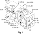
- At least one valve support module 40 of the valve support 20 is designed as a hybrid valve support module 220, wherein in the embodiment exactly one hybrid valve support module 220 is present.
- the other valve carrier modules 40 of the valve carrier 20 are each referred to as a standard valve support module 230 for better distinction.
- the hybrid valve carrier module 220 has a carrier body 41, referred to as a hybrid carrier body 221, whose component surface 140 is designated as a hybrid assembly area 222 for better distinction and defines two placement locations 140 arranged side by side in the line-up direction 60, for better distinction as first and second Hybrid placement sites 223, 224 are called.
- the orifice patterns 170 present at the two hybrid placement sites 223, 224 are referred to as first and second hybrid orifice patterns 225, 226, wherein the first hybrid orifice pattern 225 differs from the second hybrid orifice pattern 226.
- the first hybrid placement space 223 of the hybrid valve support module 220 having the first hybrid merge pattern 225 is arranged in the alignment direction 60 directly next to the control module 90, so that a valve 30 arranged on the first hybrid placement space 223, referred to as a special valve 29, acts directly adjacent to the embodiment arranged on the control module 90 control block 37.
- the second hybrid muzzle pattern 226 of the second hybrid placement space 224 is in the embodiment the same design as the other mouth pattern 170 of the standard valve support modules 230th
- valve carrier channel openings 160 of the two hybrid orifice patterns 225, 226 of the two hybrid placement locations 223, 224 preferably differ from one another in their relative positions and in their cross-sectional areas, so that valves 30 that differ from each other can be mounted at the two hybrid placement locations 223, 224 ,
- the valve carrier channel openings 160 may differ from one another only in their relative positions or only in their cross-sectional areas.
- the already mentioned special valve 29 can be mounted on the first hybrid placement space 223, which differs from the other valves 30, in particular by a different controllable fluid volume flow.
- the special valve 29 in the embodiment is preferably of a smaller size.
- the first hybrid muzzle pattern 225 is therefore smaller in size compared to all other muzzle patterns 170, so occupies a smaller area than the other muzzle patterns 170, including the second hybrid muzzle pattern 226.
- the valve carrier channel openings 160 belonging to the first hybrid muzzle pattern 225 of the first hybrid placement space 223 have a center distance relative to the respective geometric center.
- the center distance between the valve carrier channel openings 160 belonging to the first hybrid mouth pattern 225 is smaller than the center distance between the valve carrier channel openings belonging to the second hybrid mouth pattern 226 160. This applies correspondingly to the non-illustrated valve channel openings on the mounting surfaces 180 of the valves 30 to be mounted or mounted thereon.
- the second hybrid muzzle pattern 226 of the second hybrid placement slot 224 preferably matches the remaining muzzle patterns 170 of the standard valve support modules 230 adjacent to the hybrid valve support module 220 in the array direction 60.
- Each standard valve support module 230 has, for example, exactly two placement locations 140 arranged next to one another in the line-up direction 60 and matching their muzzle patterns 170.
- valve support channel mouths 160 of all orifice patterns 170 are arranged in symmetrical distribution on both sides of the center reference plane 211.
- the two hybrid placement locations 223, 224 can be different widths in adaptation to different widths of the valves 30 to be mounted thereon, also in the direction of arrangement 60, which means FIG. 3 well expressed. As a result, the width of the hybrid valve support module 220 measured in the line-up direction 60 can be minimized.
- the two hybrid placement sites 223, 224 expediently have, in addition to the hybrid muzzle patterns 225, 226, one of the above-mentioned electromechanical interface devices 32 and in each case two of the fastening holes 42 already described above.
- the electromechanical interface device 32 of each placement slot 140 of each carrier body 41 has a defined distance from the center reference plane 211.
- the electromechanical interface devices 32 of the two hybrid placement sites 223, 224 differ from each other by a different distance to the center reference plane 211.
- the electromechanical interface device 32 of the first hybrid placement slot 223 is located closer to the center reference plane 211 than the electromechanical interface device 32 of the second hybrid placement slot 224 and the other placement slots 140 located farther from the center reference plane 211.
- the mounting holes 42 of the first hybrid mounting slot 223 are aligned with the mounting holes 42 of the second hybrid mounting slot 224 in the alignment direction 60 so as to be in line.
- the attachment holes 42 of the hybrid placement places 223, 224 are spaced apart from each other in the alignment direction 60, so that, for example, the attachment holes 42 of the first hybrid placement slot 223 are closer to each other than the attachment holes 42 of the second hybrid placement slot 224 For example, differ in their measured in the alignment direction 60 distances and / or in their hole diameters from each other.
- each standard valve support module 230 following the hybrid valve support module 220 in the line-up direction 60 each have two placement locations 140 according to the preferred embodiment, it is also possible for each standard valve support module 230 only a placement space 140 or more than two placement locations 140 are formed so that a total of either only one or more valves 30 per standard valve support module 230 can be mounted.
- all the mouth patterns 170 of the standard valve carrier modules 230 coincide with one of the two hybrid mouth patterns 225, 226 of the hybrid carrier body 221 of the hybrid valve carrier module 220, so that the same valves 30 can be arranged on the associated placement sites 140, 223, 224 ,
- the hybrid valve support module 220 is disposed at the end of the row of valve support modules 40. This completes the series of slots 140 from one of the hybrid slots. Conveniently, the hybrid valve carrier module 220 in the alignment direction 60 is followed by a termination module 50, which is, for example, the control module 90 supporting the control block 37.
- the two hybrid placement locations 223, 224 are designed and arranged such that the hybrid mouth pattern 226 directly adjacent to the subsequent standard valve module 230 coincides with the mouth patterns 170 of all standard valve carrier modules 230.
- This arrangement has the advantage, for example, that the hybrid placement space 223 terminating the series of placement locations 140 is very easily accessible for mounting the special valve 29, which differs from the other valves 30 and is smaller, for example.
- An inverse Arrangement sequence of the two hybrid placement slots 223, 224 is also possible.
- the hybrid valve support module 220 does not form the end of the row of valve support modules 40, but is disposed between two standard valve support modules 230.
Landscapes
- Engineering & Computer Science (AREA)
- General Engineering & Computer Science (AREA)
- Mechanical Engineering (AREA)
- Physics & Mathematics (AREA)
- Fluid Mechanics (AREA)
- Valve Housings (AREA)
Claims (13)
- Dispositif de distribution de fluide, avec un support de soupape (20) à structure modulaire, qui est traversé par un système de canal de support de soupape (150) pouvant être traversé par du fluide et dispose de plusieurs modules de support de soupape (40), qui sont alignés dans une direction d'alignement (60) et disposent respectivement d'un corps de support (41), qui présente une surface d'équipement (110), qui définit au moins un emplacement d'équipement (140) destiné à être équipé d'une soupape (30), dans lequel le système de canal de support de soupape (150) débouche avec respectivement plusieurs embouchures de canal (160) prévues pour être reliées à une soupape (30) au niveau de chaque emplacement d'équipement (140) vers la surface d'équipement (110) et présente plusieurs canaux de passage (151) traversant de manière axiale le support de soupape (20), qui débouchent respectivement par l'intermédiaire d'une embouchure de canal (160) au niveau de chaque emplacement d'équipement (140, 223, 224) de chaque corps de support (41, 221), dans lequel les embouchures de canal (160) sont disposées de manière répartie au niveau de chaque emplacement d'équipement (140) en formant un motif d'embouchure (170), caractérisé en ce qu'au moins un module de support de soupape (40) est un module de support de soupape hybride (220), dont le corps de support (41) forme un corps de support hybride (221), dont la surface d'équipement (222) définit deux emplacements d'équipement (223, 224) disposés côte à côte dans la direction d'alignement (60), qui se distinguent l'un de l'autre par le motif d'embouchure (170, 225, 226) des embouchures de canal (160) disposées au niveau de ceux-ci.
- Dispositif de distribution de fluide selon la revendication 1, caractérisé en ce que les embouchures de canal (160) des motifs d'embouchure (170, 225, 226) des deux emplacements d'équipement (223, 224) du corps de support hybride (221) se distinguent les unes des autres par leurs positions relatives et/ou par leurs surfaces de section transversale de telle manière que les deux emplacements d'équipement (223, 224) peuvent être équipés de soupapes (29, 30) différentes.
- Dispositif de distribution de fluide selon la revendication 1 ou 2, caractérisé en ce que l'écartement central entre les embouchures de canal (160) faisant partie du même motif d'embouchure (170, 225, 226) d'un emplacement d'équipement (224) du module de support de soupape hybride (220) est plus grand que l'écartement central entre les embouchures de canal (160), faisant partie du même motif d'embouchure (170, 225, 226), de l'autre emplacement d'équipement (223) du module de support de soupape hybride (220).
- Dispositif de distribution de fluide selon l'une quelconque des revendications 1 à 3, caractérisé en ce que le motif d'embouchure (170, 225, 226) des embouchures de canal (160) d'un emplacement d'équipement (223, 224) du corps de support hybride (221) coïncide avec au moins un motif d'embouchure (170) des embouchures de canal (160) du corps de support (41) d'au moins un autre module de support de soupape (40) aligné dans la direction d'alignement (60) au niveau du module de support de soupape hybride (220), dans lequel la coïncidence de manière opportune avec tous les motifs d'embouchure (170) de tous les autres modules de support de soupape (40) est de mise.
- Dispositif de distribution de fluide selon l'une quelconque des revendications 1 à 4, caractérisé en ce que le corps de support (41) d'au moins un module de support de soupape (40) dispose de deux emplacements d'équipement (140) coïncidant dans leurs motifs d'embouchure (170), disposés côte à côte dans la direction d'alignement (60).
- Dispositif de distribution de fluide selon l'une quelconque des revendications 1 à 5, caractérisé en ce que les embouchures de canal (160) des motifs d'embouchure (170, 225, 226) de tous les emplacements d'équipement (140, 223, 224) y compris de celles de l'au moins un corps de support hybride (221) sont disposées selon une répartition symétrique de part et d'autre d'un plan de référence (211), qui s'étend le long de la direction d'alignement (60) et le long d'un axe vertical (200) orienté de manière orthogonale par rapport aux surfaces d'équipement (110, 222).
- Dispositif de distribution de fluide selon l'une quelconque des revendications 1 à 6, caractérisé en ce que chaque emplacement d'équipement (140, 223, 224) des corps de support (41, 221) dispose d'un système d'interface (32) électromécanique, qui est prévu pour être relié à un système d'actionnement (31) électrique d'une soupape (29, 30) montée ou pouvant être montée au niveau de l'emplacement d'équipement (140, 223, 224) associé, dans lequel de manière appropriée les systèmes d'interface (32) électromécaniques des deux emplacements d'équipement (223, 224) du corps de support hybride (221) présentent un écartement différent par rapport à un plan de référence (211) traversant les motifs d'embouchure (225, 226) desdits deux emplacements d'équipement (223, 224), qui s'étend le long de la direction d'alignement (60) et le long d'un axe vertical (200) orienté de manière orthogonale par rapport aux surfaces d'équipement (140, 223, 224).
- Dispositif de distribution de fluide selon l'une quelconque des revendications 1 à 7, caractérisé en ce que le système de canal de support de soupape (150) présente par emplacement d'équipement (140, 223, 224) de chaque module de support de soupape (40, 221) au moins un canal de travail (159) individuel, qui débouche d'une part au niveau d'un emplacement d'équipement (140, 223, 224) du corps de support (41, 221) associé vers la surface d'équipement (110, 222) et d'autre part vers une surface de raccordement (190) disposée à l'écart de la surface d'équipement (110, 222) du corps de support (41, 221) côté extérieur au niveau du corps de support (41, 221).
- Dispositif de distribution de fluide selon l'une quelconque des revendications 1 à 8, caractérisé en ce que le support de soupape (20) présente précisément un module de support de soupape hybride (221), qui est un module de support de soupape (40, 220) terminant la rangée de modules de support de soupape (40, 220), dans lequel de manière opportune un motif d'embouchure (225, 226) des embouchures de canal (160) du module de support de soupape hybride (220) et tous les autres motifs d'embouchure (170) des modules de support de soupape (40) restants sont identiques.
- Dispositif de distribution de fluide selon l'une quelconque des revendications 1 à 9, caractérisé en ce que respectivement une soupape (29, 30) du dispositif de distribution de fluide (10) est montée ou peut être montée pour influencer l'écoulement de fluide du fluide circulant à travers le système de canal de soupape (150) au niveau des emplacements d'équipement (140, 223, 224) des surfaces d'équipement (110, 222) des corps de support (41, 221).
- Dispositif de distribution de fluide selon la revendication 10, caractérisé en ce que sont réalisés dans les soupapes (29, 30) respectivement plusieurs canaux de soupape, qui débouchent vers une surface de montage (180), réalisée pour être montée au niveau d'un emplacement d'équipement (140, 223, 224) d'un corps de support (41, 221), de la soupape (29, 30) par l'intermédiaire d'embouchures de canal formant un motif d'embouchure, dans lequel le motif d'embouchure des embouchures de canal de la surface de montage (180) correspond au motif d'embouchure (170, 225, 226) des embouchures de canal (160) de l'emplacement d'équipement (140) respectivement associé.
- Dispositif de distribution de fluide selon l'une quelconque des revendications 1 à 11, caractérisé en ce qu'au moins un module de support de soupape hybride (220) est plus étroit dans la direction d'alignement (60) que les modules de support de soupape (40) non réalisés sous la forme d'un module de support de soupape hybride (220).
- Dispositif de distribution de fluide selon l'une quelconque des revendications 1 à 12, caractérisé en ce qu'au moins deux trous de fixation (42), en particulier des trous filetés, servant au montage amovible d'une soupape (29, 30) sont réalisés au niveau de chaque emplacement d'équipement (140, 223, 224) de la surface d'équipement (110, 222) de tous les modules de support de soupape (40, 220), dans lequel les trous de fixation (42) d'un emplacement d'équipement (223) du module de support de soupape hybride (220) se distinguent par leur écartement central mesuré dans la direction d'alignement (60) et/ou par leur diamètre de trou des trous de fixation (42) de l'autre emplacement d'équipement (224) du module de support de soupape hybride (220), et dans lequel de manière opportune les trous de fixation (42) des emplacements d'équipement (140) des modules de support de soupape (40) non réalisés sous la forme de module de support de soupape hybride (220) se distinguent par leur écartement central et leur diamètre de trou des trous de fixation (42) d'un des deux emplacements d'équipement (223, 224) du module de support de soupape hybride (220).
Applications Claiming Priority (1)
| Application Number | Priority Date | Filing Date | Title |
|---|---|---|---|
| DE102016217506.8A DE102016217506A1 (de) | 2016-09-14 | 2016-09-14 | Fluidverteilervorrichtung |
Publications (2)
| Publication Number | Publication Date |
|---|---|
| EP3296602A1 EP3296602A1 (fr) | 2018-03-21 |
| EP3296602B1 true EP3296602B1 (fr) | 2019-06-12 |
Family
ID=59581762
Family Applications (1)
| Application Number | Title | Priority Date | Filing Date |
|---|---|---|---|
| EP17185573.7A Active EP3296602B1 (fr) | 2016-09-14 | 2017-08-09 | Dispositif de distribution de fluide |
Country Status (3)
| Country | Link |
|---|---|
| EP (1) | EP3296602B1 (fr) |
| CN (1) | CN107816570B (fr) |
| DE (1) | DE102016217506A1 (fr) |
Families Citing this family (3)
| Publication number | Priority date | Publication date | Assignee | Title |
|---|---|---|---|---|
| DE102018106835A1 (de) * | 2018-03-22 | 2019-09-26 | Bürkert Werke GmbH & Co. KG | Fluidgehäuse für ein Fluidsammel- oder Fluidverteilsystem sowie Fluidsammel- oder Fluidverteilsystem |
| DE102018126116A1 (de) * | 2018-10-19 | 2020-04-23 | Robert Bosch Gmbh | Hydraulischer Verteilerblock, hydraulisches Aggregat und Verfahren |
| DE102020214470B4 (de) | 2020-11-18 | 2024-02-01 | Festo Se & Co. Kg | Ventilanordnung |
Family Cites Families (7)
| Publication number | Priority date | Publication date | Assignee | Title |
|---|---|---|---|---|
| US7344271B2 (en) | 2005-12-12 | 2008-03-18 | Norgren, Inc. | Valve island having the expansion PC board secured in the expansion station |
| DE102009017861A1 (de) * | 2009-04-17 | 2010-10-21 | Festo Ag & Co. Kg | Ventileinrichtung |
| US8307854B1 (en) * | 2009-05-14 | 2012-11-13 | Vistadeltek, Inc. | Fluid delivery substrates for building removable standard fluid delivery sticks |
| DE102010032990B4 (de) | 2010-07-31 | 2012-10-18 | Festo Ag & Co. Kg | Fluidverteileranordnung |
| CN103339389B (zh) * | 2010-12-11 | 2015-09-09 | 费斯托股份有限两合公司 | 电流体控制装置 |
| CN102913495B (zh) * | 2012-09-28 | 2015-05-20 | 上海人豪液压技术有限公司 | 采用紧凑型二通插装阀的模块化组合式电液多路阀系统 |
| CN203784005U (zh) * | 2014-03-10 | 2014-08-20 | 浙江海宏液压科技股份有限公司 | 进油阀块和复合控制流量多路阀 |
-
2016
- 2016-09-14 DE DE102016217506.8A patent/DE102016217506A1/de not_active Ceased
-
2017
- 2017-08-09 EP EP17185573.7A patent/EP3296602B1/fr active Active
- 2017-09-14 CN CN201710826885.4A patent/CN107816570B/zh active Active
Non-Patent Citations (1)
| Title |
|---|
| None * |
Also Published As
| Publication number | Publication date |
|---|---|
| DE102016217506A1 (de) | 2018-03-15 |
| CN107816570A (zh) | 2018-03-20 |
| CN107816570B (zh) | 2020-07-07 |
| EP3296602A1 (fr) | 2018-03-21 |
Similar Documents
| Publication | Publication Date | Title |
|---|---|---|
| EP2047111B1 (fr) | Agencement de soupapes modulaire pour des categories de debit differentes | |
| EP0754866B1 (fr) | Arrangement de soupape | |
| DE3525857C2 (fr) | ||
| EP2024648B1 (fr) | Agencement de soupape | |
| EP3296602B1 (fr) | Dispositif de distribution de fluide | |
| EP2923777B1 (fr) | Dispositif de tri | |
| DE102006056089A1 (de) | Ventileinrichtung | |
| DE19711227C2 (de) | Ventilanordnung | |
| DE3427589C2 (fr) | ||
| EP2084451A2 (fr) | Distributeur de lubrifiant | |
| DE202005016766U1 (de) | Ventilbatterie | |
| EP0629783B1 (fr) | ContrÔle combiné de valves pneumatiques et hydrauliques | |
| DE102015221259A1 (de) | Ventilmodul und Ventilanordnung | |
| DE102007040929B3 (de) | Ventilanordnung mit Maßnahmen zur Drucküberwachung | |
| EP0621407B1 (fr) | Ensemble valve | |
| EP2674652B1 (fr) | Agencement de soupape avec vannes à manchon | |
| DE10213397B4 (de) | Ventilanordnung | |
| DE4016368A1 (de) | Spruehkopf einer spruehvorrichtung zum aufspruehen von fluessigkeiten, insbesondere trennmitteln | |
| DE102009048018A1 (de) | Hochdruckverteilerblock einer Kühl-Schmierstoffversorgungseinrichtung | |
| EP1251283B1 (fr) | Kit pour fabriquer un dispositif de contrôle fluidique | |
| DE102006017077B4 (de) | Vorrichtung zum Aufbringen eines Befettungsmittels auf eine Werkstückoberfläche | |
| EP0281510A1 (fr) | Unité de base pour distributeurs à plusieurs voies | |
| DE102017205419A1 (de) | Ventileinheit | |
| EP2770216B1 (fr) | Agencement de vannes | |
| DE60125446T2 (de) | Eine Stütz- und Verteilungsvorrichtung eines pneumatischen Ventils |
Legal Events
| Date | Code | Title | Description |
|---|---|---|---|
| PUAI | Public reference made under article 153(3) epc to a published international application that has entered the european phase |
Free format text: ORIGINAL CODE: 0009012 |
|
| STAA | Information on the status of an ep patent application or granted ep patent |
Free format text: STATUS: THE APPLICATION HAS BEEN PUBLISHED |
|
| AK | Designated contracting states |
Kind code of ref document: A1 Designated state(s): AL AT BE BG CH CY CZ DE DK EE ES FI FR GB GR HR HU IE IS IT LI LT LU LV MC MK MT NL NO PL PT RO RS SE SI SK SM TR |
|
| AX | Request for extension of the european patent |
Extension state: BA ME |
|
| STAA | Information on the status of an ep patent application or granted ep patent |
Free format text: STATUS: REQUEST FOR EXAMINATION WAS MADE |
|
| 17P | Request for examination filed |
Effective date: 20180706 |
|
| RBV | Designated contracting states (corrected) |
Designated state(s): AL AT BE BG CH CY CZ DE DK EE ES FI FR GB GR HR HU IE IS IT LI LT LU LV MC MK MT NL NO PL PT RO RS SE SI SK SM TR |
|
| GRAP | Despatch of communication of intention to grant a patent |
Free format text: ORIGINAL CODE: EPIDOSNIGR1 |
|
| STAA | Information on the status of an ep patent application or granted ep patent |
Free format text: STATUS: GRANT OF PATENT IS INTENDED |
|
| RIC1 | Information provided on ipc code assigned before grant |
Ipc: F15B 13/08 20060101ALI20181221BHEP Ipc: F16K 27/00 20060101AFI20181221BHEP |
|
| INTG | Intention to grant announced |
Effective date: 20190128 |
|
| GRAS | Grant fee paid |
Free format text: ORIGINAL CODE: EPIDOSNIGR3 |
|
| GRAA | (expected) grant |
Free format text: ORIGINAL CODE: 0009210 |
|
| STAA | Information on the status of an ep patent application or granted ep patent |
Free format text: STATUS: THE PATENT HAS BEEN GRANTED |
|
| AK | Designated contracting states |
Kind code of ref document: B1 Designated state(s): AL AT BE BG CH CY CZ DE DK EE ES FI FR GB GR HR HU IE IS IT LI LT LU LV MC MK MT NL NO PL PT RO RS SE SI SK SM TR |
|
| REG | Reference to a national code |
Ref country code: GB Ref legal event code: FG4D Free format text: NOT ENGLISH |
|
| REG | Reference to a national code |
Ref country code: CH Ref legal event code: EP |
|
| REG | Reference to a national code |
Ref country code: AT Ref legal event code: REF Ref document number: 1142989 Country of ref document: AT Kind code of ref document: T Effective date: 20190615 |
|
| REG | Reference to a national code |
Ref country code: DE Ref legal event code: R096 Ref document number: 502017001532 Country of ref document: DE |
|
| REG | Reference to a national code |
Ref country code: IE Ref legal event code: FG4D Free format text: LANGUAGE OF EP DOCUMENT: GERMAN |
|
| REG | Reference to a national code |
Ref country code: NL Ref legal event code: MP Effective date: 20190612 |
|
| REG | Reference to a national code |
Ref country code: LT Ref legal event code: MG4D |
|
| PG25 | Lapsed in a contracting state [announced via postgrant information from national office to epo] |
Ref country code: SE Free format text: LAPSE BECAUSE OF FAILURE TO SUBMIT A TRANSLATION OF THE DESCRIPTION OR TO PAY THE FEE WITHIN THE PRESCRIBED TIME-LIMIT Effective date: 20190612 Ref country code: HR Free format text: LAPSE BECAUSE OF FAILURE TO SUBMIT A TRANSLATION OF THE DESCRIPTION OR TO PAY THE FEE WITHIN THE PRESCRIBED TIME-LIMIT Effective date: 20190612 Ref country code: AL Free format text: LAPSE BECAUSE OF FAILURE TO SUBMIT A TRANSLATION OF THE DESCRIPTION OR TO PAY THE FEE WITHIN THE PRESCRIBED TIME-LIMIT Effective date: 20190612 Ref country code: FI Free format text: LAPSE BECAUSE OF FAILURE TO SUBMIT A TRANSLATION OF THE DESCRIPTION OR TO PAY THE FEE WITHIN THE PRESCRIBED TIME-LIMIT Effective date: 20190612 Ref country code: NO Free format text: LAPSE BECAUSE OF FAILURE TO SUBMIT A TRANSLATION OF THE DESCRIPTION OR TO PAY THE FEE WITHIN THE PRESCRIBED TIME-LIMIT Effective date: 20190912 Ref country code: LT Free format text: LAPSE BECAUSE OF FAILURE TO SUBMIT A TRANSLATION OF THE DESCRIPTION OR TO PAY THE FEE WITHIN THE PRESCRIBED TIME-LIMIT Effective date: 20190612 |
|
| PG25 | Lapsed in a contracting state [announced via postgrant information from national office to epo] |
Ref country code: RS Free format text: LAPSE BECAUSE OF FAILURE TO SUBMIT A TRANSLATION OF THE DESCRIPTION OR TO PAY THE FEE WITHIN THE PRESCRIBED TIME-LIMIT Effective date: 20190612 Ref country code: BG Free format text: LAPSE BECAUSE OF FAILURE TO SUBMIT A TRANSLATION OF THE DESCRIPTION OR TO PAY THE FEE WITHIN THE PRESCRIBED TIME-LIMIT Effective date: 20190912 Ref country code: LV Free format text: LAPSE BECAUSE OF FAILURE TO SUBMIT A TRANSLATION OF THE DESCRIPTION OR TO PAY THE FEE WITHIN THE PRESCRIBED TIME-LIMIT Effective date: 20190612 Ref country code: GR Free format text: LAPSE BECAUSE OF FAILURE TO SUBMIT A TRANSLATION OF THE DESCRIPTION OR TO PAY THE FEE WITHIN THE PRESCRIBED TIME-LIMIT Effective date: 20190913 |
|
| PG25 | Lapsed in a contracting state [announced via postgrant information from national office to epo] |
Ref country code: NL Free format text: LAPSE BECAUSE OF FAILURE TO SUBMIT A TRANSLATION OF THE DESCRIPTION OR TO PAY THE FEE WITHIN THE PRESCRIBED TIME-LIMIT Effective date: 20190612 Ref country code: EE Free format text: LAPSE BECAUSE OF FAILURE TO SUBMIT A TRANSLATION OF THE DESCRIPTION OR TO PAY THE FEE WITHIN THE PRESCRIBED TIME-LIMIT Effective date: 20190612 Ref country code: SK Free format text: LAPSE BECAUSE OF FAILURE TO SUBMIT A TRANSLATION OF THE DESCRIPTION OR TO PAY THE FEE WITHIN THE PRESCRIBED TIME-LIMIT Effective date: 20190612 Ref country code: CZ Free format text: LAPSE BECAUSE OF FAILURE TO SUBMIT A TRANSLATION OF THE DESCRIPTION OR TO PAY THE FEE WITHIN THE PRESCRIBED TIME-LIMIT Effective date: 20190612 Ref country code: RO Free format text: LAPSE BECAUSE OF FAILURE TO SUBMIT A TRANSLATION OF THE DESCRIPTION OR TO PAY THE FEE WITHIN THE PRESCRIBED TIME-LIMIT Effective date: 20190612 Ref country code: PT Free format text: LAPSE BECAUSE OF FAILURE TO SUBMIT A TRANSLATION OF THE DESCRIPTION OR TO PAY THE FEE WITHIN THE PRESCRIBED TIME-LIMIT Effective date: 20191014 |
|
| REG | Reference to a national code |
Ref country code: DE Ref legal event code: R082 Ref document number: 502017001532 Country of ref document: DE Representative=s name: PATENTANWAELTE MAGENBAUER & KOLLEGEN PARTNERSC, DE Ref country code: DE Ref legal event code: R081 Ref document number: 502017001532 Country of ref document: DE Owner name: FESTO SE & CO. KG, DE Free format text: FORMER OWNER: FESTO AG & CO. KG, 73734 ESSLINGEN, DE Ref country code: DE Ref legal event code: R081 Ref document number: 502017001532 Country of ref document: DE Owner name: FESTO AG & CO. KG, DE Free format text: FORMER OWNER: FESTO AG & CO. KG, 73734 ESSLINGEN, DE |
|
| PG25 | Lapsed in a contracting state [announced via postgrant information from national office to epo] |
Ref country code: IS Free format text: LAPSE BECAUSE OF FAILURE TO SUBMIT A TRANSLATION OF THE DESCRIPTION OR TO PAY THE FEE WITHIN THE PRESCRIBED TIME-LIMIT Effective date: 20191012 Ref country code: SM Free format text: LAPSE BECAUSE OF FAILURE TO SUBMIT A TRANSLATION OF THE DESCRIPTION OR TO PAY THE FEE WITHIN THE PRESCRIBED TIME-LIMIT Effective date: 20190612 Ref country code: ES Free format text: LAPSE BECAUSE OF FAILURE TO SUBMIT A TRANSLATION OF THE DESCRIPTION OR TO PAY THE FEE WITHIN THE PRESCRIBED TIME-LIMIT Effective date: 20190612 |
|
| REG | Reference to a national code |
Ref country code: DE Ref legal event code: R097 Ref document number: 502017001532 Country of ref document: DE |
|
| RAP2 | Party data changed (patent owner data changed or rights of a patent transferred) |
Owner name: FESTO SE & CO. KG |
|
| PG25 | Lapsed in a contracting state [announced via postgrant information from national office to epo] |
Ref country code: TR Free format text: LAPSE BECAUSE OF FAILURE TO SUBMIT A TRANSLATION OF THE DESCRIPTION OR TO PAY THE FEE WITHIN THE PRESCRIBED TIME-LIMIT Effective date: 20190612 |
|
| PLBE | No opposition filed within time limit |
Free format text: ORIGINAL CODE: 0009261 |
|
| STAA | Information on the status of an ep patent application or granted ep patent |
Free format text: STATUS: NO OPPOSITION FILED WITHIN TIME LIMIT |
|
| PG25 | Lapsed in a contracting state [announced via postgrant information from national office to epo] |
Ref country code: DK Free format text: LAPSE BECAUSE OF FAILURE TO SUBMIT A TRANSLATION OF THE DESCRIPTION OR TO PAY THE FEE WITHIN THE PRESCRIBED TIME-LIMIT Effective date: 20190612 Ref country code: PL Free format text: LAPSE BECAUSE OF FAILURE TO SUBMIT A TRANSLATION OF THE DESCRIPTION OR TO PAY THE FEE WITHIN THE PRESCRIBED TIME-LIMIT Effective date: 20190612 |
|
| 26N | No opposition filed |
Effective date: 20200313 |
|
| PG25 | Lapsed in a contracting state [announced via postgrant information from national office to epo] |
Ref country code: LU Free format text: LAPSE BECAUSE OF NON-PAYMENT OF DUE FEES Effective date: 20190809 Ref country code: SI Free format text: LAPSE BECAUSE OF FAILURE TO SUBMIT A TRANSLATION OF THE DESCRIPTION OR TO PAY THE FEE WITHIN THE PRESCRIBED TIME-LIMIT Effective date: 20190612 Ref country code: IS Free format text: LAPSE BECAUSE OF FAILURE TO SUBMIT A TRANSLATION OF THE DESCRIPTION OR TO PAY THE FEE WITHIN THE PRESCRIBED TIME-LIMIT Effective date: 20200224 Ref country code: MC Free format text: LAPSE BECAUSE OF FAILURE TO SUBMIT A TRANSLATION OF THE DESCRIPTION OR TO PAY THE FEE WITHIN THE PRESCRIBED TIME-LIMIT Effective date: 20190612 |
|
| REG | Reference to a national code |
Ref country code: BE Ref legal event code: MM Effective date: 20190831 |
|
| PG2D | Information on lapse in contracting state deleted |
Ref country code: IS |
|
| PG25 | Lapsed in a contracting state [announced via postgrant information from national office to epo] |
Ref country code: IE Free format text: LAPSE BECAUSE OF NON-PAYMENT OF DUE FEES Effective date: 20190809 |
|
| PG25 | Lapsed in a contracting state [announced via postgrant information from national office to epo] |
Ref country code: BE Free format text: LAPSE BECAUSE OF NON-PAYMENT OF DUE FEES Effective date: 20190831 |
|
| REG | Reference to a national code |
Ref country code: CH Ref legal event code: PL |
|
| PG25 | Lapsed in a contracting state [announced via postgrant information from national office to epo] |
Ref country code: LI Free format text: LAPSE BECAUSE OF NON-PAYMENT OF DUE FEES Effective date: 20200831 Ref country code: CH Free format text: LAPSE BECAUSE OF NON-PAYMENT OF DUE FEES Effective date: 20200831 |
|
| PG25 | Lapsed in a contracting state [announced via postgrant information from national office to epo] |
Ref country code: CY Free format text: LAPSE BECAUSE OF FAILURE TO SUBMIT A TRANSLATION OF THE DESCRIPTION OR TO PAY THE FEE WITHIN THE PRESCRIBED TIME-LIMIT Effective date: 20190612 |
|
| PG25 | Lapsed in a contracting state [announced via postgrant information from national office to epo] |
Ref country code: MT Free format text: LAPSE BECAUSE OF FAILURE TO SUBMIT A TRANSLATION OF THE DESCRIPTION OR TO PAY THE FEE WITHIN THE PRESCRIBED TIME-LIMIT Effective date: 20190612 Ref country code: HU Free format text: LAPSE BECAUSE OF FAILURE TO SUBMIT A TRANSLATION OF THE DESCRIPTION OR TO PAY THE FEE WITHIN THE PRESCRIBED TIME-LIMIT; INVALID AB INITIO Effective date: 20170809 |
|
| PG25 | Lapsed in a contracting state [announced via postgrant information from national office to epo] |
Ref country code: MK Free format text: LAPSE BECAUSE OF FAILURE TO SUBMIT A TRANSLATION OF THE DESCRIPTION OR TO PAY THE FEE WITHIN THE PRESCRIBED TIME-LIMIT Effective date: 20190612 |
|
| P01 | Opt-out of the competence of the unified patent court (upc) registered |
Effective date: 20230623 |
|
| REG | Reference to a national code |
Ref country code: AT Ref legal event code: MM01 Ref document number: 1142989 Country of ref document: AT Kind code of ref document: T Effective date: 20220809 |
|
| PG25 | Lapsed in a contracting state [announced via postgrant information from national office to epo] |
Ref country code: AT Free format text: LAPSE BECAUSE OF NON-PAYMENT OF DUE FEES Effective date: 20220809 |
|
| PGFP | Annual fee paid to national office [announced via postgrant information from national office to epo] |
Ref country code: IT Payment date: 20230831 Year of fee payment: 7 Ref country code: GB Payment date: 20230824 Year of fee payment: 7 |
|
| PGFP | Annual fee paid to national office [announced via postgrant information from national office to epo] |
Ref country code: FR Payment date: 20230821 Year of fee payment: 7 Ref country code: DE Payment date: 20230719 Year of fee payment: 7 |