EP1013875A2 - Einrichtung und Verfahren zum Vergrössern des Querschnitts eines Erdbauwerks - Google Patents
Einrichtung und Verfahren zum Vergrössern des Querschnitts eines Erdbauwerks Download PDFInfo
- Publication number
- EP1013875A2 EP1013875A2 EP99890396A EP99890396A EP1013875A2 EP 1013875 A2 EP1013875 A2 EP 1013875A2 EP 99890396 A EP99890396 A EP 99890396A EP 99890396 A EP99890396 A EP 99890396A EP 1013875 A2 EP1013875 A2 EP 1013875A2
- Authority
- EP
- European Patent Office
- Prior art keywords
- cantilever arm
- cross
- section
- pivot axis
- support
- Prior art date
- Legal status (The legal status is an assumption and is not a legal conclusion. Google has not performed a legal analysis and makes no representation as to the accuracy of the status listed.)
- Granted
Links
- 238000000034 method Methods 0.000 title claims description 10
- 238000003801 milling Methods 0.000 claims abstract description 17
- 238000013461 design Methods 0.000 description 5
- 238000012545 processing Methods 0.000 description 3
- 238000012549 training Methods 0.000 description 3
- 238000010276 construction Methods 0.000 description 2
- 230000002349 favourable effect Effects 0.000 description 2
- 238000003754 machining Methods 0.000 description 2
- 230000009286 beneficial effect Effects 0.000 description 1
- 238000006243 chemical reaction Methods 0.000 description 1
- 238000012937 correction Methods 0.000 description 1
- 230000001419 dependent effect Effects 0.000 description 1
- 238000011161 development Methods 0.000 description 1
- 238000006073 displacement reaction Methods 0.000 description 1
- 238000007689 inspection Methods 0.000 description 1
- 238000012423 maintenance Methods 0.000 description 1
- 238000009420 retrofitting Methods 0.000 description 1
Images
Classifications
-
- E—FIXED CONSTRUCTIONS
- E03—WATER SUPPLY; SEWERAGE
- E03F—SEWERS; CESSPOOLS
- E03F3/00—Sewer pipe-line systems
- E03F3/06—Methods of, or installations for, laying sewer pipes
-
- E—FIXED CONSTRUCTIONS
- E21—EARTH OR ROCK DRILLING; MINING
- E21D—SHAFTS; TUNNELS; GALLERIES; LARGE UNDERGROUND CHAMBERS
- E21D9/00—Tunnels or galleries, with or without linings; Methods or apparatus for making thereof; Layout of tunnels or galleries
- E21D9/10—Making by using boring or cutting machines
- E21D9/1006—Making by using boring or cutting machines with rotary cutting tools
- E21D9/1013—Making by using boring or cutting machines with rotary cutting tools on a tool-carrier supported by a movable boom
- E21D9/102—Making by using boring or cutting machines with rotary cutting tools on a tool-carrier supported by a movable boom by a longitudinally extending boom being pivotable about a vertical and a transverse axis
-
- E—FIXED CONSTRUCTIONS
- E21—EARTH OR ROCK DRILLING; MINING
- E21D—SHAFTS; TUNNELS; GALLERIES; LARGE UNDERGROUND CHAMBERS
- E21D9/00—Tunnels or galleries, with or without linings; Methods or apparatus for making thereof; Layout of tunnels or galleries
- E21D9/01—Methods or apparatus for enlarging or restoring the cross-section of tunnels, e.g. by restoring the floor to its original level
Definitions
- the present invention relates to a device for editing and enlarging the clear Cross-section or the inner contour of an earthwork, z.
- a device for editing and enlarging the clear Cross-section or the inner contour of an earthwork z.
- B. a channel with a Milling tool on a support that can be positioned in the cross-section to be machined a cantilever arm is mounted, the carrier rollers for support and for moving in the cross section to be machined.
- a processing device for enlarging the clear channel cross section is, for example in AT 396 270.
- the removal tool held movably along a backdrop, the backdrop being the one to be processed Profile must be produced accordingly in order to adapt the processing machine in each case.
- the known device has a carrier which braces in the clear cross section becomes.
- the machining tool on Hold the frame by a freely guided robot arm the movements of which conform to the profile are controllable.
- WO 90/12979 shows a device for processing pipe systems in the mold a pig that is mounted on several support wheels.
- the newt carries on an outrigger arm a tool.
- the boom arm can be pivoted in the radial direction on a bogie arranged, which is pivotable about a longitudinal axis.
- the tool can any position on the pipe wall.
- Such a device is for inspection or minor maintenance work, especially in duct systems with a small cross-section, quite suitable.
- rough work with one Devices of this construction are not easily executable.
- the cross-sectional expansion by milling is problematic, because in this way no favorable angles of attack are accessible for the milling tool.
- the relatively large ones that occur Forces are not optimally absorbed by the movement mechanism.
- the object of the present invention is to avoid these disadvantages and to provide a device to create the type mentioned, in which a known movable basic device can be adapted to any contours in a particularly simple manner and is automatic Control of the feed, for example along a route guidance device, is made possible becomes.
- this object is achieved in that the cantilever arm by a horizontal Axis and a further axis is articulated on the girder and that the articulation point the boom arm is adjustable in height.
- the inventive design is such that the Pivot axis for the horizontal pivoting of the cantilever arm is essentially normal runs on the horizontal swivel axis, which means in particular of the circular shape deviating internal contours or clear cross sections with the extension arm and the milling tools can be brushed safely.
- the necessary control signals arise with such a design as X and Y coordinates of the respective target profile in the machining Cross section, the orientation of the substantially horizontal Swivel axis is sufficient to allow an automatic movement along a beacon analogous to To enable procedures along a route guidance device.
- the training is such that the actuators for the vertical and horizontal swiveling of the boom arm of hydraulic cylinders are formed, the position of which is monitored by a control circuit and dependent is adjusted by a predetermined target profile.
- the cardanic bearing and the device for adjusting the height of the horizontal swivel axis later can be grown to any known movable devices, due to the geometric design an automatic process is possible in a simple manner.
- a safe adjustment and positioning of the device in the clear cross section can in can be ensured in a simple manner in that the carrier has at least three support rollers Arms, which is arranged in the cross-sectional plane Y-shaped and towards Inner surface of the profile are adjustable.
- the use of a substantially Y-shaped one The arrangement of the support rollers here allows, in particular, for cross sections which differ from the Circular deviate, largely self-centering the device, so that the required Effort for subsequent corrections on the route beacon can be kept low. Process profiles can be used to create different profiles with the hydraulic pistons control exactly, the device universal without complex retrofitting Use can come.
- the training is such that the Milling tool at the rear end of the support on the extension arm in the direction of advance or displacement is arranged.
- the milling tools of milling drums or milling heads can be used in a particularly simple manner be formed, the axis of rotation of which is aligned with the axis of the cantilever arm.
- a Design can be a respective head shape and head geometry Largely extensive contact of the cutting tools with the inner contour or the inner wall of the clear cross-section to be enlarged, thereby reducing the working speed can be increased.
- the axis of rotation of the milling tool lies transversely to the axis of the cantilever arm.
- the device is preferably designed such that the Pivot axes of the cantilever arm on a directional beam, in particular a laser beam, can be aligned.
- a directional beam in particular a laser beam
- the training is like this made that at least one of the rollers is connected to a travel drive.
- the present invention relates to a method for editing and enlarging the clear cross-section or the inner contour of an earthwork, z. B. a channel, preferably using a device of the type described above.
- a milling tool is used that is on a cantilever arm attached, gimbaled at a point that is level with a horizontal Diameter of an outer envelope circle is arranged around the target profile shape.
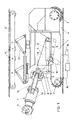
- a frame 1 can be seen on which wheels 2 and 3 are rotatably mounted.
- the impeller 3 is connected to a drive motor, not shown, the impellers are movable on the sole of a channel profile 4.
- the machine base frame 1 there is an extension arm 7 on a rocker arm 5 horizontal axis 6 pivoted in the height direction.
- the boom arm 7 is articulated here, the essentially vertical pivot axis being designated 8 is.
- the cantilever arm 7 carries at its front end coaxial to the axis of the cantilever arm rotatably mounted milling or cutting tools 9, the corresponding drive motor is designated by 10.
- the essentially vertical pivot axis 8 is here encompassed by a fork 11 of the cantilever arm 7, so that the reaction forces are reliably absorbed is made possible.
- the pivot drive for pivoting the cantilever arm 7 around the substantially horizontal axis 6 is formed by a hydraulic cylinder 12 which is attached to an arm 13 of the universal joint attacks.
- the pivoting in a substantially horizontal direction is effected by the hydraulic cylinder 14, these two hydraulic cylinders 14, 12 are connected via control lines 15 and 16 to a central control device 17 which also processes the signals of a route control device, not shown.
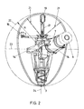
- the Swing arm 5 is pivoted by a hydraulic cylinder 18, so that the horizontal pivot axis 6 runs essentially diametrically in the enveloping circle of the channel cross section of the channel 4. Centering or further support is ensured by support rollers 19 which can be pressed against the inner wall of the channel 4 via hydraulic cylinders 20 and in a common carrier 21 are stored.
- the carrier 21, which were indicated by dash-dotted lines, are preferably arranged in a Y-shape be, with a substantially egg-shaped cross-section together with the lower driven support roller 3 self-adjustment is possible.
- the support rollers 19 can also deviates from the position indicated by dash-dotted lines in any way are, as is illustrated by the rollers 19 drawn in full lines.
- the enveloping circles surrounding the profile cross section are included 22 designated.
- the essentially horizontal pivot axis is in each case on the horizontal diameter 23 of this enveloping circle aligned, so that an exact adjustment the entire facility can be carried out on a route beacon.
- can separate hydraulic cylinders for pivoting the boom arm 7 on both sides 14 are used, the substantially horizontal pivot axis 6 in the vertical direction along the vertical longitudinal median plane indicated at 24 to be machined clear cross section is adjustable.
Landscapes
- Engineering & Computer Science (AREA)
- Mining & Mineral Resources (AREA)
- Life Sciences & Earth Sciences (AREA)
- Environmental & Geological Engineering (AREA)
- General Life Sciences & Earth Sciences (AREA)
- Geochemistry & Mineralogy (AREA)
- Geology (AREA)
- Hydrology & Water Resources (AREA)
- Health & Medical Sciences (AREA)
- Public Health (AREA)
- Water Supply & Treatment (AREA)
- Earth Drilling (AREA)
- Excavating Of Shafts Or Tunnels (AREA)
- Laser Beam Processing (AREA)
- Sewage (AREA)
- Soil Working Implements (AREA)
- Inorganic Insulating Materials (AREA)
Abstract
Description
- Fig. 1
- eine schematische Seitenansicht einer erfindungsgemäßen Einrichtung und
- Fig. 2
- eine Ansicht auf die erfindungsgemäße Einrichtung von hinten in Vortriebsrichtung gesehen.
Claims (11)
- Einrichtung zum Bearbeiten und Vergrößern des lichten Querschnitts bzw. der Innenkontur eines Erdbauwerks, z. B. eines Kanals, mit einem Fräswerkzeug (9), das auf einem im zu bearbeitenden Querschnitt positionierbaren Träger (1) auf einem Auslegerarm (7) gelagert ist, wobei der Träger (1) Rollen (19) zur Abstützung und zum Verfahren in dem zu bearbeitenden Querschnitt aufweist, dadurch gekennzeichnet , dass der Auslegerarm (7) um eine horizontale Schwenkachse (6) und um eine weitere Schwenkachse (8) kardanisch am Träger (1) angelenkt ist und dass der Anlenkpunkt des Auslegerarms (7) höhenverstellbar ist.
- Einrichtung nach Anspruch 1, dadurch gekennzeichnet, dass der Anlenkpunkt des Auslegerarms (7) auf einer Schwinge (5) angeordnet ist, die relativ zum Träger (1) verschwenkbar angeordnet ist.
- Einrichtung nach einem der Ansprüche 1 oder 2, dadurch gekennzeichnet, dass die horizontale Schwenkachse (6) des Auslegerarms im Bereich eines horizontalen Durchmessers eines äußeren Hüllkreises um die Sollprofilform angeordnet ist.
- Einrichtung nach einem der Ansprüche 1 bis 3, dadurch gekennzeichnet, dass die weitere Schwenkachse (8) im wesentlichen normal zur horizontalen Schwenkachse (6) angeordnet ist.
- Einrichtung nach einem der Ansprüche 1 bis 4, dadurch gekennzeichnet, dass Hydraulikzylinder (12, 14) zur Verschwenkung des Auslegerarms (7) vorgesehen sind, wobei deren Position von einer Steuerschaltung überwacht ist, und in Abhängigkeit von einem vorgegebenen Sollprofil verstellbar ist.
- Einrichtung nach einem der Ansprüche 1 bis 5, dadurch gekennzeichnet, dass der Träger (1) wenigstens drei Stützrollen (19) an Armen trägt, welche Arme in der Querschnittsebene vorzugsweise Y-förmig angeordnet und in Richtung zur Innenfläche des Profils verstellbar sind.
- Einrichtung nach einem der Ansprüche 1 bis 6, dadurch gekennzeichnet, dass das Fräswerkzeug (9) an dem in Vortriebs- bzw. Verschieberichtung hinteren Ende des Trägers (1) am Auslegerarm (7) angeordnet ist, wobei das Fräswerkzeug (9) vorzugsweise eine Rotationsachse aufweist, die mit der Achse des Auslegerarms (7) fluchtet.
- Einrichtung nach einem der Ansprüche 1 bis 7, dadurch gekennzeichnet, dass die Schwenkachsen des Auslegerarms (7) an einem Richtstrahl, insbesondere an einem Laserstrahl ausrichtbar sind.
- Einrichtung nach einem der Ansprüche 1 bis 8, wobei der Träger (1) auf Laufrädern (2,3) gelagert ist, dadurch gekennzeichnet, dass zumindest ein Laufrad (2,3) antreibbar ausgebildet ist.
- Einrichtung nach einem der Ansprüche 1 bis 9, dadurch gekennzeichnet, dass wenigstens eine Abstützrolle (19) antreibbar ausgebildet ist.
- Verfahren zum Bearbeiten und Vergrößern des lichten Querschnitts bzw. der Innenkontur eines Erdbauwerkes, z. B. eines Kanals, vorzugsweise unter Verwendung einer Einrichtung nach einem der Ansprüche 1 bis 9, dadurch gekennzeichnet, dass ein Fräswerkzeug (9) verwendet wird, das an einem Auslegerarm (7) befestigt ist, der kardanisch an einem Punkt gelagert ist, der auf der Höhe eines horizontalen Durchmessers eines äußeren Hüllkreises um die Sollprofilform angeordnet ist.
Priority Applications (1)
| Application Number | Priority Date | Filing Date | Title |
|---|---|---|---|
| AT99890396T ATE283962T1 (de) | 1998-12-21 | 1999-12-21 | Einrichtung und verfahren zum vergrössern des querschnitts eines erdbauwerks |
Applications Claiming Priority (2)
| Application Number | Priority Date | Filing Date | Title |
|---|---|---|---|
| AT0212398A AT408110B (de) | 1998-12-21 | 1998-12-21 | Einrichtung zum bearbeiten und vergrössern des lichten querschnittes eines erdbauwerkes |
| AT212398 | 1998-12-21 |
Publications (3)
| Publication Number | Publication Date |
|---|---|
| EP1013875A2 true EP1013875A2 (de) | 2000-06-28 |
| EP1013875A3 EP1013875A3 (de) | 2001-08-16 |
| EP1013875B1 EP1013875B1 (de) | 2004-12-01 |
Family
ID=3528273
Family Applications (1)
| Application Number | Title | Priority Date | Filing Date |
|---|---|---|---|
| EP99890396A Expired - Lifetime EP1013875B1 (de) | 1998-12-21 | 1999-12-21 | Einrichtung und Verfahren zum Vergrössern des Querschnitts eines Erdbauwerks |
Country Status (6)
| Country | Link |
|---|---|
| EP (1) | EP1013875B1 (de) |
| JP (1) | JP2000186494A (de) |
| KR (1) | KR100369752B1 (de) |
| AT (2) | AT408110B (de) |
| CA (1) | CA2292725A1 (de) |
| DE (1) | DE59911189D1 (de) |
Cited By (2)
| Publication number | Priority date | Publication date | Assignee | Title |
|---|---|---|---|---|
| CN107605030A (zh) * | 2017-09-19 | 2018-01-19 | 郑州星和凯贸易有限公司 | 管道疏通清障车 |
| CN115229579A (zh) * | 2022-09-20 | 2022-10-25 | 江苏强弘阀门有限公司 | 一种阀门管件打磨设备 |
Families Citing this family (4)
| Publication number | Priority date | Publication date | Assignee | Title |
|---|---|---|---|---|
| US4060304A (en) * | 1976-07-01 | 1977-11-29 | Abramson Joseph O | Battery cables and process for making same |
| CN101391314B (zh) * | 2008-09-25 | 2012-09-05 | 湖州机床厂有限公司 | 一种球面内孔镗铣机构 |
| CN114109430B (zh) * | 2021-11-30 | 2024-05-03 | 中国矿业大学 | 一种硬岩切割截割两用掘进机 |
| CN118327605B (zh) * | 2024-06-14 | 2024-10-22 | 陕西延长石油矿业有限责任公司 | 一种全断面掘进机用钻进式清渣取样机械臂 |
Citations (2)
| Publication number | Priority date | Publication date | Assignee | Title |
|---|---|---|---|---|
| WO1990012979A1 (en) | 1989-04-26 | 1990-11-01 | Gammelgaard, Lone, Lykke | Apparatus for use in renovation of tube systems, in particular sewer tube systems |
| AT396270B (de) | 1989-04-27 | 1993-07-26 | Wiener Betriebs & Bau | Bearbeitungseinrichtung zur vergroesserung des lichten querschnittes der innenwand eines, insbesondere von der kreisform abweichenden profiles eines erdbauwerkes |
Family Cites Families (8)
| Publication number | Priority date | Publication date | Assignee | Title |
|---|---|---|---|---|
| DE1248589B (de) * | 1965-03-11 | 1967-08-31 | Gewerk Eisenhuette Westfalia | Gewinnungs- und Vortriebsmaschine |
| DE2027192A1 (de) * | 1970-06-03 | 1972-02-03 | Paurat, Friedrich Wilhelm, 4222 Friedrichsfeld | Vortriebsmaschine |
| DE2113190B1 (de) * | 1971-03-18 | 1972-05-25 | Paurat F | Verfahren und Vorrichtung zum Vortrieb von Strecken und Tunneln |
| GB1501113A (en) * | 1974-04-20 | 1978-02-15 | Anderson Mavor Ltd | Tunnelling machines |
| FR2459360B1 (fr) * | 1979-06-21 | 1986-04-18 | Tim Tech Ind Minieres | Systeme pour creuser des galeries souterraines |
| DE2933766C2 (de) * | 1979-08-21 | 1982-08-12 | Mannesmann AG, 4000 Düsseldorf | Teilschnitt-Streckenvortriebsmaschine |
| DE3738802A1 (de) * | 1987-11-14 | 1989-05-24 | Atlas Copco Eickhoff Road | Teilschnittmaschine zum vortreiben von strecken oder tunnels |
| DE3740753A1 (de) * | 1987-12-02 | 1989-06-15 | Atlas Copco Eickhoff Road | Tragarmanordnung an teilschnittmaschinen |
-
1998
- 1998-12-21 AT AT0212398A patent/AT408110B/de not_active IP Right Cessation
-
1999
- 1999-12-20 CA CA002292725A patent/CA2292725A1/en not_active Abandoned
- 1999-12-21 AT AT99890396T patent/ATE283962T1/de active
- 1999-12-21 KR KR10-1999-0059858A patent/KR100369752B1/ko not_active Expired - Fee Related
- 1999-12-21 EP EP99890396A patent/EP1013875B1/de not_active Expired - Lifetime
- 1999-12-21 DE DE59911189T patent/DE59911189D1/de not_active Expired - Lifetime
- 1999-12-21 JP JP11362053A patent/JP2000186494A/ja active Pending
Patent Citations (2)
| Publication number | Priority date | Publication date | Assignee | Title |
|---|---|---|---|---|
| WO1990012979A1 (en) | 1989-04-26 | 1990-11-01 | Gammelgaard, Lone, Lykke | Apparatus for use in renovation of tube systems, in particular sewer tube systems |
| AT396270B (de) | 1989-04-27 | 1993-07-26 | Wiener Betriebs & Bau | Bearbeitungseinrichtung zur vergroesserung des lichten querschnittes der innenwand eines, insbesondere von der kreisform abweichenden profiles eines erdbauwerkes |
Cited By (2)
| Publication number | Priority date | Publication date | Assignee | Title |
|---|---|---|---|---|
| CN107605030A (zh) * | 2017-09-19 | 2018-01-19 | 郑州星和凯贸易有限公司 | 管道疏通清障车 |
| CN115229579A (zh) * | 2022-09-20 | 2022-10-25 | 江苏强弘阀门有限公司 | 一种阀门管件打磨设备 |
Also Published As
| Publication number | Publication date |
|---|---|
| EP1013875B1 (de) | 2004-12-01 |
| AT408110B (de) | 2001-09-25 |
| DE59911189D1 (de) | 2005-01-05 |
| ATA212398A (de) | 2001-01-15 |
| EP1013875A3 (de) | 2001-08-16 |
| CA2292725A1 (en) | 2000-06-21 |
| KR20000048297A (ko) | 2000-07-25 |
| ATE283962T1 (de) | 2004-12-15 |
| KR100369752B1 (ko) | 2003-01-30 |
| JP2000186494A (ja) | 2000-07-04 |
Similar Documents
| Publication | Publication Date | Title |
|---|---|---|
| EP0204694B1 (de) | Vorrichtung zur durchführung von ausbesserungsarbeiten an einer schadhaft gewordenen, nichtbegehbaren rohrleitung | |
| DE69102883T2 (de) | Verfahren und maschine zum graben von strecken, tunneln, abbauräumen, kavernen oder dergleichen. | |
| DE69219429T2 (de) | Bodenflächenstrahlgerät | |
| DE10013674A1 (de) | Stumpffräse sowie Verfahren zum Betrieb derselben | |
| DE102010011385A1 (de) | Parabolspiegelwaschfahrzeug | |
| EP0310074B1 (de) | An ein fahrbares Tragwerk anbaubare Fräse | |
| EP3613900B1 (de) | Bodenbearbeitungsmaschine mit schnell vom fräsaggregat entfernbarer fördereinrichtung und verfahren hierzu | |
| DE102007060215A1 (de) | Vorrichtung zum Bearbeiten einer Fahrkante | |
| EP3845710B1 (de) | Abtragendes bodenbearbeitungsverfahren mit bezüglich der vortriebsrichtung schräg angestelltem abtragendem werkzeug und zur ausführung des verfahrens ausgebildete bodenbearbeitungsmaschine | |
| DE102010006608A1 (de) | Vorrichtung zum Hochdruck-Wasserstrahlschneiden in geschlossenen Kanälen | |
| AT408110B (de) | Einrichtung zum bearbeiten und vergrössern des lichten querschnittes eines erdbauwerkes | |
| DE3916113A1 (de) | Verfahren und vorrichtung zur zerspanenden bearbeitung der innenoberflaeche von hohlkoerpern | |
| EP0169393B1 (de) | Vorrichtung zur Herstellung von unterirdischen, nicht begehbare Querschnitte aufweisenden Durchbohrungen | |
| EP0333712B1 (de) | Bohr-gewinnungsanlage für den bergbau | |
| DE3313435C2 (de) | Tunnelvortriebsmaschine | |
| DE202012010050U1 (de) | Fluidstrahlschneidvorrichtung mit Bohreinheit | |
| EP4046749A1 (de) | Distanzeinrichtung für eine schleifwalze | |
| DE3140203C2 (de) | "Rotierender Schneidkopf einer Strecken- oder Tunnelvortriebsmaschine" | |
| DE2816723C2 (de) | ||
| DE4440498A1 (de) | Vorrichtung zur gesteuerten Ausschrämung gewölbter Wandflächen, insbesondere von Tunnelwänden | |
| DE3923970A1 (de) | Verfahren und vorrichtung zum herstellen von trennschnitten in baukoerpern, wie von betonhohlkoerpern | |
| EP3879032A1 (de) | Stelleinrichtung zum positionieren eines bearbeitungswerkzeuges relativ zu einer schiene | |
| DE19911382A1 (de) | Werkzeugführungssystem | |
| DE3412219C2 (de) | ||
| DE3140707C2 (de) |
Legal Events
| Date | Code | Title | Description |
|---|---|---|---|
| PUAI | Public reference made under article 153(3) epc to a published international application that has entered the european phase |
Free format text: ORIGINAL CODE: 0009012 |
|
| AK | Designated contracting states |
Kind code of ref document: A2 Designated state(s): AT BE CH CY DE DK ES FI FR GB GR IE IT LI LU MC NL PT SE |
|
| AX | Request for extension of the european patent |
Free format text: AL;LT;LV;MK;RO;SI |
|
| PUAL | Search report despatched |
Free format text: ORIGINAL CODE: 0009013 |
|
| AK | Designated contracting states |
Kind code of ref document: A3 Designated state(s): AT BE CH CY DE DK ES FI FR GB GR IE IT LI LU MC NL PT SE |
|
| AX | Request for extension of the european patent |
Free format text: AL;LT;LV;MK;RO;SI |
|
| 17P | Request for examination filed |
Effective date: 20011027 |
|
| AKX | Designation fees paid |
Free format text: AT BE CH CY DE DK ES FI FR GB GR IE IT LI LU MC NL PT SE |
|
| 17Q | First examination report despatched |
Effective date: 20030716 |
|
| GRAP | Despatch of communication of intention to grant a patent |
Free format text: ORIGINAL CODE: EPIDOSNIGR1 |
|
| GRAS | Grant fee paid |
Free format text: ORIGINAL CODE: EPIDOSNIGR3 |
|
| GRAA | (expected) grant |
Free format text: ORIGINAL CODE: 0009210 |
|
| AK | Designated contracting states |
Kind code of ref document: B1 Designated state(s): AT BE CH CY DE DK ES FI FR GB GR IE IT LI LU MC NL PT SE |
|
| PG25 | Lapsed in a contracting state [announced via postgrant information from national office to epo] |
Ref country code: SE Free format text: LAPSE BECAUSE OF FAILURE TO SUBMIT A TRANSLATION OF THE DESCRIPTION OR TO PAY THE FEE WITHIN THE PRESCRIBED TIME-LIMIT Effective date: 20041201 Ref country code: NL Free format text: LAPSE BECAUSE OF FAILURE TO SUBMIT A TRANSLATION OF THE DESCRIPTION OR TO PAY THE FEE WITHIN THE PRESCRIBED TIME-LIMIT Effective date: 20041201 Ref country code: IT Free format text: LAPSE BECAUSE OF FAILURE TO SUBMIT A TRANSLATION OF THE DESCRIPTION OR TO PAY THE FEE WITHIN THE PRE;WARNING: LAPSES OF ITALIAN PATENTS WITH EFFECTIVE DATE BEFORE 2007 MAY HAVE OCCURRED AT ANY TIME BEFORE 2007. THE CORRECT EFFECTIVE DATE MAY BE DIFFERENT FROM THE ONE RECORDED.SCRIBED TIME-LIMIT Effective date: 20041201 Ref country code: IE Free format text: LAPSE BECAUSE OF FAILURE TO SUBMIT A TRANSLATION OF THE DESCRIPTION OR TO PAY THE FEE WITHIN THE PRESCRIBED TIME-LIMIT Effective date: 20041201 Ref country code: GB Free format text: LAPSE BECAUSE OF FAILURE TO SUBMIT A TRANSLATION OF THE DESCRIPTION OR TO PAY THE FEE WITHIN THE PRESCRIBED TIME-LIMIT Effective date: 20041201 Ref country code: FI Free format text: LAPSE BECAUSE OF FAILURE TO SUBMIT A TRANSLATION OF THE DESCRIPTION OR TO PAY THE FEE WITHIN THE PRESCRIBED TIME-LIMIT Effective date: 20041201 Ref country code: CY Free format text: LAPSE BECAUSE OF FAILURE TO SUBMIT A TRANSLATION OF THE DESCRIPTION OR TO PAY THE FEE WITHIN THE PRESCRIBED TIME-LIMIT Effective date: 20041201 |
|
| REG | Reference to a national code |
Ref country code: GB Ref legal event code: FG4D Free format text: NOT ENGLISH |
|
| REG | Reference to a national code |
Ref country code: CH Ref legal event code: EP |
|
| REG | Reference to a national code |
Ref country code: IE Ref legal event code: FG4D Free format text: GERMAN |
|
| PG25 | Lapsed in a contracting state [announced via postgrant information from national office to epo] |
Ref country code: MC Free format text: LAPSE BECAUSE OF NON-PAYMENT OF DUE FEES Effective date: 20041231 Ref country code: LI Free format text: LAPSE BECAUSE OF NON-PAYMENT OF DUE FEES Effective date: 20041231 Ref country code: CH Free format text: LAPSE BECAUSE OF NON-PAYMENT OF DUE FEES Effective date: 20041231 Ref country code: BE Free format text: LAPSE BECAUSE OF NON-PAYMENT OF DUE FEES Effective date: 20041231 |
|
| REF | Corresponds to: |
Ref document number: 59911189 Country of ref document: DE Date of ref document: 20050105 Kind code of ref document: P |
|
| PG25 | Lapsed in a contracting state [announced via postgrant information from national office to epo] |
Ref country code: LU Free format text: LAPSE BECAUSE OF NON-PAYMENT OF DUE FEES Effective date: 20050201 |
|
| PG25 | Lapsed in a contracting state [announced via postgrant information from national office to epo] |
Ref country code: GR Free format text: LAPSE BECAUSE OF FAILURE TO SUBMIT A TRANSLATION OF THE DESCRIPTION OR TO PAY THE FEE WITHIN THE PRESCRIBED TIME-LIMIT Effective date: 20050301 Ref country code: DK Free format text: LAPSE BECAUSE OF FAILURE TO SUBMIT A TRANSLATION OF THE DESCRIPTION OR TO PAY THE FEE WITHIN THE PRESCRIBED TIME-LIMIT Effective date: 20050301 |
|
| PG25 | Lapsed in a contracting state [announced via postgrant information from national office to epo] |
Ref country code: ES Free format text: LAPSE BECAUSE OF FAILURE TO SUBMIT A TRANSLATION OF THE DESCRIPTION OR TO PAY THE FEE WITHIN THE PRESCRIBED TIME-LIMIT Effective date: 20050312 |
|
| NLV1 | Nl: lapsed or annulled due to failure to fulfill the requirements of art. 29p and 29m of the patents act | ||
| GBV | Gb: ep patent (uk) treated as always having been void in accordance with gb section 77(7)/1977 [no translation filed] |
Effective date: 20041201 |
|
| BERE | Be: lapsed |
Owner name: ANGERLEHNER HOCH- UND TIEFBAU GMBH Effective date: 20041231 |
|
| REG | Reference to a national code |
Ref country code: IE Ref legal event code: FD4D |
|
| REG | Reference to a national code |
Ref country code: CH Ref legal event code: PL |
|
| ET | Fr: translation filed | ||
| PLBE | No opposition filed within time limit |
Free format text: ORIGINAL CODE: 0009261 |
|
| STAA | Information on the status of an ep patent application or granted ep patent |
Free format text: STATUS: NO OPPOSITION FILED WITHIN TIME LIMIT |
|
| 26N | No opposition filed |
Effective date: 20050902 |
|
| BERE | Be: lapsed |
Owner name: *ANGERLEHNER HOCH- UND TIEFBAU G.M.B.H. Effective date: 20041231 |
|
| PG25 | Lapsed in a contracting state [announced via postgrant information from national office to epo] |
Ref country code: PT Free format text: LAPSE BECAUSE OF NON-PAYMENT OF DUE FEES Effective date: 20050501 |
|
| REG | Reference to a national code |
Ref country code: FR Ref legal event code: TP |
|
| PGFP | Annual fee paid to national office [announced via postgrant information from national office to epo] |
Ref country code: FR Payment date: 20110104 Year of fee payment: 12 |
|
| REG | Reference to a national code |
Ref country code: FR Ref legal event code: ST Effective date: 20120831 |
|
| PGFP | Annual fee paid to national office [announced via postgrant information from national office to epo] |
Ref country code: DE Payment date: 20121126 Year of fee payment: 14 |
|
| PGFP | Annual fee paid to national office [announced via postgrant information from national office to epo] |
Ref country code: AT Payment date: 20121126 Year of fee payment: 14 |
|
| PG25 | Lapsed in a contracting state [announced via postgrant information from national office to epo] |
Ref country code: FR Free format text: LAPSE BECAUSE OF NON-PAYMENT OF DUE FEES Effective date: 20120102 |
|
| REG | Reference to a national code |
Ref country code: DE Ref legal event code: R119 Ref document number: 59911189 Country of ref document: DE |
|
| REG | Reference to a national code |
Ref country code: AT Ref legal event code: MM01 Ref document number: 283962 Country of ref document: AT Kind code of ref document: T Effective date: 20131221 |
|
| REG | Reference to a national code |
Ref country code: DE Ref legal event code: R119 Ref document number: 59911189 Country of ref document: DE Effective date: 20140701 |
|
| PG25 | Lapsed in a contracting state [announced via postgrant information from national office to epo] |
Ref country code: DE Free format text: LAPSE BECAUSE OF NON-PAYMENT OF DUE FEES Effective date: 20140701 |
|
| PG25 | Lapsed in a contracting state [announced via postgrant information from national office to epo] |
Ref country code: AT Free format text: LAPSE BECAUSE OF NON-PAYMENT OF DUE FEES Effective date: 20131221 |