EP1012113B1 - Elektrisch unterstützte teiloxydation von leichten kohlenwasserstoffen mittels sauerstoff - Google Patents
Elektrisch unterstützte teiloxydation von leichten kohlenwasserstoffen mittels sauerstoff Download PDFInfo
- Publication number
- EP1012113B1 EP1012113B1 EP98943485A EP98943485A EP1012113B1 EP 1012113 B1 EP1012113 B1 EP 1012113B1 EP 98943485 A EP98943485 A EP 98943485A EP 98943485 A EP98943485 A EP 98943485A EP 1012113 B1 EP1012113 B1 EP 1012113B1
- Authority
- EP
- European Patent Office
- Prior art keywords
- plasma
- conversion
- plasma compartment
- post
- oxygen
- Prior art date
- Legal status (The legal status is an assumption and is not a legal conclusion. Google has not performed a legal analysis and makes no representation as to the accuracy of the status listed.)
- Expired - Lifetime
Links
Images

Classifications
-
- C—CHEMISTRY; METALLURGY
- C01—INORGANIC CHEMISTRY
- C01B—NON-METALLIC ELEMENTS; COMPOUNDS THEREOF; METALLOIDS OR COMPOUNDS THEREOF NOT COVERED BY SUBCLASS C01C
- C01B3/00—Hydrogen; Gaseous mixtures containing hydrogen; Separation of hydrogen from mixtures containing it; Purification of hydrogen; Reversible storage of hydrogen
- C01B3/02—Production of hydrogen; Production of gaseous mixtures containing hydrogen
- C01B3/32—Production of hydrogen; Production of gaseous mixtures containing hydrogen by reaction of gaseous or liquid organic compounds with gasifying agents, e.g. water, carbon dioxide or air
- C01B3/34—Production of hydrogen; Production of gaseous mixtures containing hydrogen by reaction of gaseous or liquid organic compounds with gasifying agents, e.g. water, carbon dioxide or air by reaction of hydrocarbons with gasifying agents
- C01B3/36—Production of hydrogen; Production of gaseous mixtures containing hydrogen by reaction of gaseous or liquid organic compounds with gasifying agents, e.g. water, carbon dioxide or air by reaction of hydrocarbons with gasifying agents using oxygen; using mixtures containing oxygen as gasifying agents
-
- C—CHEMISTRY; METALLURGY
- C01—INORGANIC CHEMISTRY
- C01B—NON-METALLIC ELEMENTS; COMPOUNDS THEREOF; METALLOIDS OR COMPOUNDS THEREOF NOT COVERED BY SUBCLASS C01C
- C01B3/00—Hydrogen; Gaseous mixtures containing hydrogen; Separation of hydrogen from mixtures containing it; Purification of hydrogen; Reversible storage of hydrogen
- C01B3/02—Production of hydrogen; Production of gaseous mixtures containing hydrogen
- C01B3/32—Production of hydrogen; Production of gaseous mixtures containing hydrogen by reaction of gaseous or liquid organic compounds with gasifying agents, e.g. water, carbon dioxide or air
- C01B3/34—Production of hydrogen; Production of gaseous mixtures containing hydrogen by reaction of gaseous or liquid organic compounds with gasifying agents, e.g. water, carbon dioxide or air by reaction of hydrocarbons with gasifying agents
-
- B—PERFORMING OPERATIONS; TRANSPORTING
- B01—PHYSICAL OR CHEMICAL PROCESSES OR APPARATUS IN GENERAL
- B01J—CHEMICAL OR PHYSICAL PROCESSES, e.g. CATALYSIS OR COLLOID CHEMISTRY; THEIR RELEVANT APPARATUS
- B01J19/00—Chemical, physical or physico-chemical processes in general; Their relevant apparatus
- B01J19/08—Processes employing the direct application of electric or wave energy, or particle radiation; Apparatus therefor
- B01J19/087—Processes employing the direct application of electric or wave energy, or particle radiation; Apparatus therefor employing electric or magnetic energy
- B01J19/088—Processes employing the direct application of electric or wave energy, or particle radiation; Apparatus therefor employing electric or magnetic energy giving rise to electric discharges
-
- C—CHEMISTRY; METALLURGY
- C01—INORGANIC CHEMISTRY
- C01B—NON-METALLIC ELEMENTS; COMPOUNDS THEREOF; METALLOIDS OR COMPOUNDS THEREOF NOT COVERED BY SUBCLASS C01C
- C01B3/00—Hydrogen; Gaseous mixtures containing hydrogen; Separation of hydrogen from mixtures containing it; Purification of hydrogen; Reversible storage of hydrogen
- C01B3/02—Production of hydrogen; Production of gaseous mixtures containing hydrogen
- C01B3/32—Production of hydrogen; Production of gaseous mixtures containing hydrogen by reaction of gaseous or liquid organic compounds with gasifying agents, e.g. water, carbon dioxide or air
- C01B3/34—Production of hydrogen; Production of gaseous mixtures containing hydrogen by reaction of gaseous or liquid organic compounds with gasifying agents, e.g. water, carbon dioxide or air by reaction of hydrocarbons with gasifying agents
- C01B3/342—Production of hydrogen; Production of gaseous mixtures containing hydrogen by reaction of gaseous or liquid organic compounds with gasifying agents, e.g. water, carbon dioxide or air by reaction of hydrocarbons with gasifying agents with the aid of electrical means, electromagnetic or mechanical vibrations, or particle radiations
-
- C—CHEMISTRY; METALLURGY
- C07—ORGANIC CHEMISTRY
- C07C—ACYCLIC OR CARBOCYCLIC COMPOUNDS
- C07C2/00—Preparation of hydrocarbons from hydrocarbons containing a smaller number of carbon atoms
- C07C2/76—Preparation of hydrocarbons from hydrocarbons containing a smaller number of carbon atoms by condensation of hydrocarbons with partial elimination of hydrogen
- C07C2/80—Processes with the aid of electrical means
-
- H—ELECTRICITY
- H05—ELECTRIC TECHNIQUES NOT OTHERWISE PROVIDED FOR
- H05H—PLASMA TECHNIQUE; PRODUCTION OF ACCELERATED ELECTRICALLY-CHARGED PARTICLES OR OF NEUTRONS; PRODUCTION OR ACCELERATION OF NEUTRAL MOLECULAR OR ATOMIC BEAMS
- H05H1/00—Generating plasma; Handling plasma
- H05H1/24—Generating plasma
- H05H1/48—Generating plasma using an arc
- H05H1/482—Arrangements to provide gliding arc discharges
-
- B—PERFORMING OPERATIONS; TRANSPORTING
- B01—PHYSICAL OR CHEMICAL PROCESSES OR APPARATUS IN GENERAL
- B01J—CHEMICAL OR PHYSICAL PROCESSES, e.g. CATALYSIS OR COLLOID CHEMISTRY; THEIR RELEVANT APPARATUS
- B01J2219/00—Chemical, physical or physico-chemical processes in general; Their relevant apparatus
- B01J2219/08—Processes employing the direct application of electric or wave energy, or particle radiation; Apparatus therefor
- B01J2219/0894—Processes carried out in the presence of a plasma
-
- C—CHEMISTRY; METALLURGY
- C01—INORGANIC CHEMISTRY
- C01B—NON-METALLIC ELEMENTS; COMPOUNDS THEREOF; METALLOIDS OR COMPOUNDS THEREOF NOT COVERED BY SUBCLASS C01C
- C01B2203/00—Integrated processes for the production of hydrogen or synthesis gas
- C01B2203/02—Processes for making hydrogen or synthesis gas
- C01B2203/0205—Processes for making hydrogen or synthesis gas containing a reforming step
- C01B2203/0211—Processes for making hydrogen or synthesis gas containing a reforming step containing a non-catalytic reforming step
- C01B2203/0216—Processes for making hydrogen or synthesis gas containing a reforming step containing a non-catalytic reforming step containing a non-catalytic steam reforming step
-
- C—CHEMISTRY; METALLURGY
- C01—INORGANIC CHEMISTRY
- C01B—NON-METALLIC ELEMENTS; COMPOUNDS THEREOF; METALLOIDS OR COMPOUNDS THEREOF NOT COVERED BY SUBCLASS C01C
- C01B2203/00—Integrated processes for the production of hydrogen or synthesis gas
- C01B2203/02—Processes for making hydrogen or synthesis gas
- C01B2203/0205—Processes for making hydrogen or synthesis gas containing a reforming step
- C01B2203/0211—Processes for making hydrogen or synthesis gas containing a reforming step containing a non-catalytic reforming step
- C01B2203/0222—Processes for making hydrogen or synthesis gas containing a reforming step containing a non-catalytic reforming step containing a non-catalytic carbon dioxide reforming step
-
- C—CHEMISTRY; METALLURGY
- C01—INORGANIC CHEMISTRY
- C01B—NON-METALLIC ELEMENTS; COMPOUNDS THEREOF; METALLOIDS OR COMPOUNDS THEREOF NOT COVERED BY SUBCLASS C01C
- C01B2203/00—Integrated processes for the production of hydrogen or synthesis gas
- C01B2203/02—Processes for making hydrogen or synthesis gas
- C01B2203/025—Processes for making hydrogen or synthesis gas containing a partial oxidation step
- C01B2203/0255—Processes for making hydrogen or synthesis gas containing a partial oxidation step containing a non-catalytic partial oxidation step
-
- C—CHEMISTRY; METALLURGY
- C01—INORGANIC CHEMISTRY
- C01B—NON-METALLIC ELEMENTS; COMPOUNDS THEREOF; METALLOIDS OR COMPOUNDS THEREOF NOT COVERED BY SUBCLASS C01C
- C01B2203/00—Integrated processes for the production of hydrogen or synthesis gas
- C01B2203/02—Processes for making hydrogen or synthesis gas
- C01B2203/0283—Processes for making hydrogen or synthesis gas containing a CO-shift step, i.e. a water gas shift step
-
- C—CHEMISTRY; METALLURGY
- C01—INORGANIC CHEMISTRY
- C01B—NON-METALLIC ELEMENTS; COMPOUNDS THEREOF; METALLOIDS OR COMPOUNDS THEREOF NOT COVERED BY SUBCLASS C01C
- C01B2203/00—Integrated processes for the production of hydrogen or synthesis gas
- C01B2203/04—Integrated processes for the production of hydrogen or synthesis gas containing a purification step for the hydrogen or the synthesis gas
-
- C—CHEMISTRY; METALLURGY
- C01—INORGANIC CHEMISTRY
- C01B—NON-METALLIC ELEMENTS; COMPOUNDS THEREOF; METALLOIDS OR COMPOUNDS THEREOF NOT COVERED BY SUBCLASS C01C
- C01B2203/00—Integrated processes for the production of hydrogen or synthesis gas
- C01B2203/04—Integrated processes for the production of hydrogen or synthesis gas containing a purification step for the hydrogen or the synthesis gas
- C01B2203/0465—Composition of the impurity
- C01B2203/0495—Composition of the impurity the impurity being water
-
- C—CHEMISTRY; METALLURGY
- C01—INORGANIC CHEMISTRY
- C01B—NON-METALLIC ELEMENTS; COMPOUNDS THEREOF; METALLOIDS OR COMPOUNDS THEREOF NOT COVERED BY SUBCLASS C01C
- C01B2203/00—Integrated processes for the production of hydrogen or synthesis gas
- C01B2203/06—Integration with other chemical processes
- C01B2203/062—Hydrocarbon production, e.g. Fischer-Tropsch process
-
- C—CHEMISTRY; METALLURGY
- C01—INORGANIC CHEMISTRY
- C01B—NON-METALLIC ELEMENTS; COMPOUNDS THEREOF; METALLOIDS OR COMPOUNDS THEREOF NOT COVERED BY SUBCLASS C01C
- C01B2203/00—Integrated processes for the production of hydrogen or synthesis gas
- C01B2203/08—Methods of heating or cooling
- C01B2203/0805—Methods of heating the process for making hydrogen or synthesis gas
- C01B2203/0861—Methods of heating the process for making hydrogen or synthesis gas by plasma
-
- C—CHEMISTRY; METALLURGY
- C01—INORGANIC CHEMISTRY
- C01B—NON-METALLIC ELEMENTS; COMPOUNDS THEREOF; METALLOIDS OR COMPOUNDS THEREOF NOT COVERED BY SUBCLASS C01C
- C01B2203/00—Integrated processes for the production of hydrogen or synthesis gas
- C01B2203/12—Feeding the process for making hydrogen or synthesis gas
- C01B2203/1205—Composition of the feed
- C01B2203/1211—Organic compounds or organic mixtures used in the process for making hydrogen or synthesis gas
- C01B2203/1235—Hydrocarbons
- C01B2203/1241—Natural gas or methane
-
- C—CHEMISTRY; METALLURGY
- C01—INORGANIC CHEMISTRY
- C01B—NON-METALLIC ELEMENTS; COMPOUNDS THEREOF; METALLOIDS OR COMPOUNDS THEREOF NOT COVERED BY SUBCLASS C01C
- C01B2203/00—Integrated processes for the production of hydrogen or synthesis gas
- C01B2203/12—Feeding the process for making hydrogen or synthesis gas
- C01B2203/1205—Composition of the feed
- C01B2203/1211—Organic compounds or organic mixtures used in the process for making hydrogen or synthesis gas
- C01B2203/1235—Hydrocarbons
- C01B2203/1247—Higher hydrocarbons
-
- C—CHEMISTRY; METALLURGY
- C01—INORGANIC CHEMISTRY
- C01B—NON-METALLIC ELEMENTS; COMPOUNDS THEREOF; METALLOIDS OR COMPOUNDS THEREOF NOT COVERED BY SUBCLASS C01C
- C01B2203/00—Integrated processes for the production of hydrogen or synthesis gas
- C01B2203/16—Controlling the process
- C01B2203/1614—Controlling the temperature
- C01B2203/1619—Measuring the temperature
-
- C—CHEMISTRY; METALLURGY
- C01—INORGANIC CHEMISTRY
- C01B—NON-METALLIC ELEMENTS; COMPOUNDS THEREOF; METALLOIDS OR COMPOUNDS THEREOF NOT COVERED BY SUBCLASS C01C
- C01B2203/00—Integrated processes for the production of hydrogen or synthesis gas
- C01B2203/16—Controlling the process
- C01B2203/1628—Controlling the pressure
-
- C—CHEMISTRY; METALLURGY
- C01—INORGANIC CHEMISTRY
- C01B—NON-METALLIC ELEMENTS; COMPOUNDS THEREOF; METALLOIDS OR COMPOUNDS THEREOF NOT COVERED BY SUBCLASS C01C
- C01B2203/00—Integrated processes for the production of hydrogen or synthesis gas
- C01B2203/16—Controlling the process
- C01B2203/1628—Controlling the pressure
- C01B2203/1633—Measuring the pressure
-
- C—CHEMISTRY; METALLURGY
- C01—INORGANIC CHEMISTRY
- C01B—NON-METALLIC ELEMENTS; COMPOUNDS THEREOF; METALLOIDS OR COMPOUNDS THEREOF NOT COVERED BY SUBCLASS C01C
- C01B2203/00—Integrated processes for the production of hydrogen or synthesis gas
- C01B2203/16—Controlling the process
- C01B2203/1628—Controlling the pressure
- C01B2203/1638—Adjusting the pressure
-
- C—CHEMISTRY; METALLURGY
- C01—INORGANIC CHEMISTRY
- C01B—NON-METALLIC ELEMENTS; COMPOUNDS THEREOF; METALLOIDS OR COMPOUNDS THEREOF NOT COVERED BY SUBCLASS C01C
- C01B2203/00—Integrated processes for the production of hydrogen or synthesis gas
- C01B2203/16—Controlling the process
- C01B2203/169—Controlling the feed
Definitions
- the present invention relates to a process for the conversion of light hydrocarbons (HCs) through the use of plasma and, in particular, through sliding electric discharges in the presence of oxygen O 2 and possibly of water vapor H 2 O added to these HCs.
- HCs light hydrocarbons
- a catalytic device is generally selected: presence of solid material under highly dispersed and active form (with a specific surface of at least one hundred m 2 per gram) for temperatures that may be reached without great difficulty.
- the invention comprises a process and device is defined in the claims for electrically assisted partial oxidation of light hydrocarbons by oxygen.
- the purpose of the process and device is to produce gases rich in CO and H 2 that may also have high contents of C 2 H 4 and C 2 H 2 , without any formation of soot or coke by assisting with gliding electric discharge plasma the partial oxidation of hydrocarbons, accompanied by their steam reforming and/or reforming with CO 2 ,.
- This mixture of products is achieved in a plasma reactor with gliding electric discharges that glow in the compartment brought to a temperature lower than 1200°C and at a pressure of less than 6 bars.
- the discharges act directly in an exothermic reactive medium consisting of hydrocarbons mixed with gaseous oxygen of any origin, and possibly with H 2 O and/or CO 2 .
- the flow of products activated by the plasma and exiting the zone comes into contact with a metal or ceramic material placed in the compartment that is brought to a temperature not exceeding 1100°C. This material becomes active in the presence of the flow of products and, as such, it contributes to the enhancement of the conversion of the products exiting the plasma compartment into the final product.
- the process is illustrated by the conversion of some typical mixtures of light HCs (containing mainly methane CH 4 and ethane C 2 H 6 , propane C 3 H 8 and the two butanes C 4 H 10 ) in a gliding discharge reactor fitted with a post-plasma compartment filled with solid material.
- These HC mixtures may contain any quantities of nitrogen N 2 and/or carbon dioxide CO 2 . Therefore, the invention may be applied to any pure HC such as CH 4 , C 2 H 6 , C 3 H 8 or C 4 H 10 , and to their natural or industrial mixtures such as NG, "associated" gas of petroleum wells, flare gas, pyrolytic gas, "mine gas", biogas, etc.
- synthesis gas also referred to as “syngas”
- syngas is a mixture composed mainly of hydrogen H 2 and carbon monoxide CO.
- the conversion may also be performed in order to produce a syngas containing other valuable products such as ethylene (C 2 H 4 ) and acetylene (C 2 H 2 ).
- HCs according to the endothermal reactions (3) to (9) and (13) to (16) would require the addition of preferably "clean" energy, detached from any external combustion that is not cost-effective and is highly polluting.
- the best way to promote these reactions would be to perform electric arcs and/or discharges directly in the medium to be converted, by imposing a permanent distribution of energy in the greatest volume to be processed.
- the transfer of electric energy to the gas medium would be achieved through the direct transfer of the energy to the molecules. That would result in phenomena of excitation, ionization, dissociation and also in the Joule effect, by considering the ionized medium as a gaseous conductor.
- the gas medium which was rendered conductive after the ionization (itself due to a dielectric breakdown, thus a preionization) between electrodes brought to different potentials, would be considered as an electrical resistance and, at the same time, as some kind of electrolyte in a gaseous phase: the plasma.
- the plasma is defined as the 4 th state of matter and, therefore, cannot under any circumstances be used as a similarity criterion for different previously known processes.
- the plasma is a gas medium where particles are partially ionized.
- the macroscopic physical quantity - the temperature - is the same for all the components: that represents the thermodynamic equilibrium.
- Such conditions are easy to obtain: all that is required is to provide a great amount of energy, as in the case of plasma torches (“plasmatrons") where the plasma is produced by a very high current electric arc.
- thermal plasmas there are also other devices capable of generating this state, such as induction or radiofrequency (RF) torches where the gas medium enters into resonance with a very high frequency electromagnetic field.
- RF radiofrequency
- thermal plasmas are known as thermal plasmas. It is obvious that a thermal plasma will modify the chemistry of a gas medium by destroying practically all molecules, especially those that are brittle like HCs. The fragments remaining at the end of the process, after a sudden temperature drop by quenching with no recovery of energy, originate from partial recombination phenomena that produce simple molecules.
- chemistry offers very poor possibilities, requires a lot of energy and is faced with problems linked to high temperature, in particular, the resistance of materials.
- thermodynamic non equilibrium Such plasmas are sometimes referred to as "low temperature" plasmas, although the notion of temperature can no longer be used.
- microwaves, electron beams, flame fronts etc. generators of such plasmas that may be converted to the industrial scale are rare and serve only for a very specific purpose. That is why such plasmas are seldom used in chemistry.
- the GlidArc thus enables the chemist to consider the distribution of an energy supply directly into the gas mixture and, for example, to resort to catalysts.
- the chemist may also distribute the energy directly either as thermal energy or as chemical energy. He may also act upon the flux that is still charged with active species exiting the zone of arcs or gliding discharges, in order to cause a reaction between these species and the feedstock to be converted or reconverted in a post-plasma zone.
- the GlidArc is very well adapted for a pure water vapor supply as the only plasma forming medium.
- Water vapor superheating tests with these devices were performed at the laboratory scale and at the atmospheric pressure.
- the improved GlidArc was fed very humid water vapor at 105°C. No deterioration of the plasma generated fed with water vapor was observed after several long experiments.
- the water vapor thus superheated at the atmospheric pressure and chemically activated by the presence of H, O, OH and other metastable species, can be interesting for drying or for chemical transformations, see P. CZERNICHOWSKI and A.
- Another new idea is to divide a gliding discharge reactor into two compartments.
- a more or less virtual separation for example in the form of a perforated diaphragm
- We isolate this compartment thermally so that the temperature of its walls and the electrodes themselves may be raised as much as possible.
- we add another "post-plasma" compartment where the reactions generated in the plasma zone can be completed and where the products generated in the plasma zone can eventually be modified.
- the two compartments (or zones) of the reactor communicate through a relatively large hole, or preferably a perforated plate, or even a porous material, enabling the reactants and the active species produced in the plasma zone to penetrate in the post-plasma zone.
- Another new idea is to partially fill the post-plasma zone with a solid material playing the role of a contact on which we promote reactive exchanges between the species generated in the plasma zone.
- the solid material does not need to be known as a catalyst. It may become so by contact with the species originating from the plasma zone.
- gliding discharge reactors can be used.
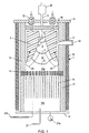
- the one illustrated in Fig. 1 is a laboratory scale device used to illustrate the invention. Naturally, this is only a non-restrictive example for the elaboration of a future industrial scale reactor.
- the gliding discharge reactor /1/ uses six electrodes /2/ in profiled stainless steel sheet 2 mm thick (only two of the six electrodes arranged symmetrically around the flow axis of the fluid to be processed are shown on Fig. 1).
- Each of the electrodes has a length of 8 cm and a width of 25 mm.
- the electrodes delimit a nozzle-shaped volume /3/ where gliding electric discharges /4/ may develop.
- This reactor contains a simple nozzle /5/ with a diameter of 4 mm, blowing the premixed fluid /6/ to be converted in the space /7/ between the electrodes arranged so that the fluid flows along the central part of these electrodes exposed to the discharges.
- Another more complex "double nozzle” (but not shown in this Fig. 1) can also be used; it consists of two concentric pipes through which arrive the hydrocarbon feedstock, possibly mixed with water vapor, and the oxygen or oxygen-enriched air, or even the atmospheric air, all three being eventually mixed with water vapor. In this case, the reactants are mixed in such new "double nozzle” or even outside of it, just near the electrodes.
- Several nozzles may be arranged in the same reactor.
- the process is sequential and the lifetime of a discharge /4/ observed ranges from 1 to 20 ms, depending on the linear speed of the fluid in zones /7/, /9/, /3/ and /10/, between the electrodes /2/.
- the gliding discharges /4/ have variable characteristics from the point /9/ where they are initiated to their extinction /10/ with, in particular, dissipation of energy that increase over time.
- the tubular reactor is closed by two covers. One of them /11/ supports the electrodes that are isolated electrically with high voltage connections /12/. The other /13/ closes the reactor on the other side and comprises a product output tube /22/.
- a perforated metal or ceramic plate /14/ separates a plasma zone /15a/ and a post-plasma zone /15b/ partially filled with solid material. The two zones are housed within the same reactor /1/.
- the plate /14/ makes it possible to run products from the plasma treatment to the post-plasma zone /15b/.
- the reactor (outer diameter of 85 mm and height of 88 cm) is insulated externally by a ceramic felt /16/. We packed the inner walls of the post-plasma zone of the reactor with a ceramic tube /17/ with an inner diameter of 55 mm.
- the plasma zone is insulated by a heat resisting felt /18/.
- the total free volume (in terms of fluid) inside the reactor is 1.9 dm 3 .
- the volume of the solid material /19/ inserted in the post-plasma zone /15b/ (in most cases we use metal Ni sticks with a total mass of 1.5 kg) is 170 cm 3 , which corresponds to a geometric surface of 1670 cm 2 .
- the ratio between the volumes of solid material inserted in the post-plasma zone and the unfilled volume of this zone is only 1 to 6.5, while the ratio between the volumes of the plasma zone /15a/ and that of the post-plasma zone is 1 to 2.4.
- No part of the reactor is cooled in a forced manner. The incoming fluids /6/ are mixed away from the injection nozzle /5/, in the nozzle itself, or even near the nozzle.
- this separating plate /14/ thus dividing the reactor in two parts: an electric discharge plasma compartment /15a/ and a post-plasma compartment /15b/.
- the perforated plate provides for the flow of reactants (partially consumed) and "long-living" active species resulting from the excitation of the gases by the gliding discharges.
- the conversion is thus susceptible of being completed in the presence of solid material /19/ and in an environment where the temperature is much lower than that of the walls and electrodes of the plasma zone /15a/.
- the fluid once in this post-plasma zone, cannot reenter the plasma zone.
- the luminous zone of the sliding electric discharges, as well as part of the wall of the zone, can be observed through a glass /24/ with a diameter of 15 mm, in order to verify the proper operation of the reactor and to determine the temperature in the compartment /15a/. Very important information may be derived from the plasma emission spectrum.
- the conversion of NGs is generally sufficient with a single run through a single reactor. Otherwise, the products partially converted in a reactor may be reprocessed in several reactors thus described and arranged sequentially (not represented).
- the reactor is fed controlled volumes (by mass flowmeters) of gas taken in gas cylinders (or other sources) and/or water vapor originating from a steam generator.
- the reactor may also be fed with water through the use of a metering pump.
- the constant flow of such liquid, controlled by a valve and a flowmeter, is thus evaporated in the furnace /20/, to be then injected in the reactor, being previously mixed or not with another fluid of the process.
- the gliding discharges inside the reactor are fed by a special high voltage system that provides both the preionization of the medium and then the transfer of electric energy to the plasma.
- the electric power of the reactor used varies between 0.15 and 0.56 kW under 0.12 or 0.25A for a flow rate of fluid to be treated of 1.3 to 2.6 m 3 (n)/h; the energy supply in relation to the feedstock is 0.10 to 0.34 kWh/m 3 (n).
- Fig. 2 is a schematic representation of the overall equipment.
- the reactor /1/ is fed by a special high voltage electric generator /25/.
- This reactor is operated directly with, as a plasma forming gas, a NG taken from the city system /26/ or from a pressurized cylinder /27/ containing a simulated NG, mixed with oxygen /28/ or oxygen-enriched air 28/, or even atmospheric air /28/ and possibly water vapor (or liquid water) /29/.
- the gas flows are controlled by mass flowmeters /30/.
- the incoming gas mixture may be sampled for chromatographic analysis by a bypass /31/.
- the flow of water vapor is also known following the calibration of the metering pump of the device /29/.
- a thermocouple /32/ makes it possible to measure the temperature of the fluid at the inlet of the injection nozzle, while an optical pyrometer /33/ and a thermocouple /21b/ indicate the temperatures in the two compartments /15a/ and /15b/ of the reactor.
- a pressure gauge /21a/ provides at all times the pressure inside of the reactor.
- the products exiting the reactor are cooled in an air heat exchanger /35/.
- the gases Upon exiting the exchanger, the gases are directed to a direction reversing valve /36/ that is used to redirect them either to the analysis /37/ or to the evacuation stack /38a/.
- a direction reversing valve /36/ that is used to redirect them either to the analysis /37/ or to the evacuation stack /38a/.
- the water is deposited in the cooled flask /39/ and in an absorbing material /40/.
- Valve /41/ being previously closed and valves /42a/ and /42b/ open, the dry gas flows through a bulb or a balloon /43/, then through a gas meter /44/, and exits the experimental device through a pipe /38b/ located near the evacuation stack.
- the temperature of the gas exiting the meter /44/ is measured with a thermometer /45/.
- we also measure the atmospheric pressure with a barometer, in order to reset our volume balances to their normal conditions marked ("n").
- Table 1 and Table 2 summarize respectively four and six examples of partial oxidation of NG with pure oxygen without the addition of water vapor.
- Table 3 summarizes seven examples of partial oxidation of the NG with pure oxygen and added water vapor, in the presence of a solid metal body inserted in the post-plasma zone of the reactor. Another body, this time ceramic, was then placed in this zone and the results of four tests with pure oxygen and added water vapor are presented in Table 4.
- Table 5 summarizes seven new examples of partial oxidation of the NG with oxygen-enriched air and added water vapor, in the presence of the same metal body in the post-plasma zone.
- Table 6 summarizes seven examples of partial oxidation of NG with atmospheric air in a "shortened” reactor filled (or not) with different bodies (metal or ceramic) in the post-plasma zone. Finally, Table 7 presents the results of 4 pairs of comparative tests with/and without discharges in the plasma zone.
- Table 1 summarizes the four tests 20 to 23 of partial oxidation of a NG with oxygen without added water vapor. Whenever we use the term "added”, we emphasize the extemal origin of this reactant which appears anyway (but in a lesser quantity) as a product of further oxidation reactions (11) and (12).
- the NG (with a volume composition of 97.3% CH 4 , 1.4% C 2 H 6 , 0.3% C 3 H 8 and 0.1% C 4 H 10 ) is mixed with pure oxygen according to a constant O 2 /HC ratio of 0.48, and then injected into the reactor without preheating. The flow rate of the mixture (1.3 m 3 (n)/h), the pressure in the reactor (1.5 bar) and the electric supply settings are maintained constant.
- the reactor initially cold at the beginning of the tests, is heated progressively and the exiting products are sampled when the thermocouple installed in the post-plasma zone indicates the temperatures listed in column 2 of the table. At that time, we also measure the electric powers dissipated in the plasma zone. They are not strictly constant due to the evolution of the temperatures of all the elements of the plasma zone, but the specific power SE varies little: 0.29 ⁇ 0.03 kWh/m 3 (n). Ex. Temp. H 2 /CO SG/HC EC Conv.
- Table 2 summarizes the six tests 27a to 30 and 67 to 68 of partial oxidation of a NG with oxygen without added water vapor.
- a pressure increase from 1.5 to 2.0 bars results beneficial for the quantity of syngas produced from a unit volume of HCs. That is also visible in the figures pertaining to the carbon conversion rate, as well as on the selectivities towards CO and undesired products. We also performed other tests under a pressure approximating 6 bars. We currently consider this limit as the maximum value with which our equipment will work in a stable and problem-free manner. Furthermore, we are considering developing a partial oxidation of HCs under relatively low pressures for specific applications such as the chemical conversion of petroleum associated gas (otherwise burned by the flares at quasi-atmospheric pressures), the biogases produced in low pressure digesters, hydrocarbon permeates resulting from a membrane separation, etc. Our relatively low pressure process thus makes it possible to avoid energy-starved compressors and facilities with a higher technological requirements due to the classic high pressure technology of the catalytic auto-thermal process.
- Table 3 summarizes the seven tests 38b to 44 of partial oxidation of a NG with oxygen and added water vapor.
- Table 4 summarizes the four tests 46 to 49 of partial oxidation of a NG with oxygen and added water vapor in the presence of another inert material in the post-plasma compartment.
- Table 4 summarizes the four tests 46 to 49 of partial oxidation of a NG with oxygen and added water vapor in the presence of another inert material in the post-plasma compartment.
- the question was: is the mixed conversion O 2 + H 2 O of a NG sensitive to the nature of the solid introduced in the post-plasma zone?
- the "heavy" NG tested had the following composition: 90.7% CH 4 , 6.9% C 2 H 6 , 1.9% C 3 H 8 , and 0.5% C 4 H 10 (therefore, very close to the composition of the NG tested during tests 38b to 44).
- Table 5 summarizes the seven tests 51 to 57 of partial oxidation of a NG with oxygen-enriched air and eventually mixed with water vapor.
- the questions were whether we could convert a NG with such enriched air (for example, of membrane origin and thus much less expensive and more readily available than the pure oxygen of cryogenic origin) and whether we could obtain a syngas at a reasonable energy price, while also having a H 2 /CO ratio of approximately 2.
- the target NG selected was quite heavy: 91.2% CH 4 , 6.5% C 2 H 6 , 1.7% C 3 H 8 , and 0.5% C 4 H 10 .
- ballast up to 40% by volume of carbon dioxide, CO 2 , present in some NGs that we also tested does not prevent the smooth conversion of HCs into syngas.
- Such ballast can be compared to the ballast of inert nitrogen, although a fraction of CO 2 may actively escape through reactions (15) and (16), upon the conversion of the original HC carbon into CO, which increases the content of this valuable product.
- the volume of the reactor zone housing the Ni sticks is 660 cm 3 . Under the conditions of exp. 33/34, this volume, which comprises a Ni (geometric) surface of 1670 cm 2 , is covered by a flow of products of approximately 6.6 m 3 /h (at the pressure and temperature of the zone). This gives a space velocity of approximately 10,000 h- 1 .
- thermo-catalytic processes under high pressure. Exposed to a flame relatively rich in oxygen (theoretically, we should stop at O 2 /HC ⁇ 0.5) at more than 2000°C, the HCs are consumed preferentially into CO 2 and H 2 O according to reactions (11) and (12), rather than (1) and (2), leaving large unconsummated quantities of HCs (mainly the chemically strongest methane). It is only in the presence of a large mass of brittle catalyst that the total conversion of HCs is completed according to the endothermic reforming reactions (3), (4), (15) and (16), on a catalytic bed exposed to very high temperatures (1100 to 1400°C). This catalyst and its support should thus exhibit a very high resistance and very good stability under these severe conditions.
- CHRISTENSEN and PRIMDAHL do not mention any O 2 /C ratio lower than 0.54 or any H 2 O/C ratio lower than 0.58 in any industrial example or pilot test. On the contrary, they emphasize the need to add at least these quantities of oxygen and water vapor to ensure the appropriate operation of their burner, which also requires a special recirculation. However, we can reduce these ratios to 0.22 and zero, respectively, since we have another adjustment device: the very active energy of electric discharges added to the highly substoichiometric flame.
- the report of NIRULA provides some information regarding the volume of the industrial reactor (94 m') and the flows of incoming gas (200,000 m 3 (n)/h). From the analyses of gas at the outlet of the reactor, we were able to calculate the space velocity of the reactor, which operates under 68 bars and at a very high outlet temperature of 1350°C. This velocity is approximately 310 h -1 , which does not compare at all with ours which, even brought to the total volume of the reactor, is 3500 h -1 .
- This post-plasma zone at a temperature of less than 1100°C, can be filled partially with a metal or ceramic solid material which, in contact with a flow of treatment products derived from the plasma hydrocarbon feedstock, becomes active and contributes to the total or quasi-total conversion of HCs into syngas, with a cogeneration of more or less ethylene and acetylene.
- a metal or ceramic solid material which, in contact with a flow of treatment products derived from the plasma hydrocarbon feedstock, becomes active and contributes to the total or quasi-total conversion of HCs into syngas, with a cogeneration of more or less ethylene and acetylene.
- HCs such as CH 4 , C 2 H 6 , C 3 H 8 and/or C 4 H 10
- This is performed without using any conventional catalysts.
- the reactor and its assembly operate with surprising smoothness, without deterioration of the electrodes, electrode holders, perforated diaphragm, or walls of the reactor, or the post-plasma zone, all of which undergo the action of incoming reactants and exiting products.
- the process consists in producing these gases through gliding electric discharges that glow directly in the NGs mixed with water vapor and/or pure oxygen, or oxygen-enriched air, or even atmospheric air, and this under almost any proportions. This causes the partial oxidation and/or cracking of these HCs while avoiding the shortcomings of the existing processes.
- the reactants partially converted in a gliding discharge compartment, then penetrate in another post-plasma compartment that is eventually separated from the direct reaction zone by a perforated diaphragm. There, in the presence of species still active produced in the discharges and transported by the gas exiting the plasma zone, the gases undergo an additional conversion at a lower temperature than that which is present in the direct reaction zone.
- the process places the partial oxidation and cracking of HCs in the active presence of water vapor and/or element oxygen, without requiring the intervention of any other reactants or catalysts, as well as without the formation of soot, coke or tar, which would hinder the proper operation of the reactor.
- the tests clearly demonstrate the easiness of a partial oxidation, combined with a steam reforming initiated by the addition of water vapor in the hydrocarbon feedstock, or by the water vapor created spontaneously by side reactions of over-oxidation.
- This partial oxidation and the steam reforming are also accompanied by the reforming with carbon dioxide present in the NG, or created by the side reactions of over-oxidation.
- This partial oxidation of gaseous HCs is also accompanied by a non-catalytic cracking of hydrocarbons.
- the process also makes it possible to transfer directly the electric energy under high voltage and relatively low current in an exothermic reactive medium.
- These electrical conditions combined with a high velocity of the plasma forming medium in the discharge zone cause a strong disturbance of the electric and also thermodynamic equilibrium.
- the material injected in this non equilibrium plasma zone of the gliding discharge device thus reacts in a non-thermal fashion.
- the process may therefore provide some of the following benefits:
Landscapes
- Chemical & Material Sciences (AREA)
- Organic Chemistry (AREA)
- Engineering & Computer Science (AREA)
- Chemical Kinetics & Catalysis (AREA)
- Physics & Mathematics (AREA)
- Plasma & Fusion (AREA)
- Health & Medical Sciences (AREA)
- General Health & Medical Sciences (AREA)
- Spectroscopy & Molecular Physics (AREA)
- Toxicology (AREA)
- Combustion & Propulsion (AREA)
- Inorganic Chemistry (AREA)
- Electromagnetism (AREA)
- Mechanical Engineering (AREA)
- Physical Or Chemical Processes And Apparatus (AREA)
- Hydrogen, Water And Hydrids (AREA)
- Organic Low-Molecular-Weight Compounds And Preparation Thereof (AREA)
- Low-Molecular Organic Synthesis Reactions Using Catalysts (AREA)
- Oxygen, Ozone, And Oxides In General (AREA)
- Production Of Liquid Hydrocarbon Mixture For Refining Petroleum (AREA)
- Carbon And Carbon Compounds (AREA)
Claims (8)
- Verfahren zur Umwandlung von leichten Kohlenwasserstoffen, die Methan CH4, Ethan C2H6, Propan C3H8 und Butane C4H10 umfassen, durch teilweises Oxidieren mit elementarem Sauerstoff O2 oder durch gleichzeitiges Reformieren mit O2 und Wasserdampf H2O,
dadurch gekennzeichnet daß:wobei die Temperatur der Umwandlung irgendeines festen Elementes im Kontakt mit den Entladungen im Bereich von etwa 900 bis 1200°C liegt und die chemischen Spezies der Synthesegasprodukte in der Kammer nach dem Plasma in Gegenwart eines Metall- oder Keramikkörpers bei einer Temperatur, die 1100°C nicht übersteigt, zur weiteren Umwandlung der die Plasmakammer verlassenden Produkte beitragen.ein oder mehr als ein Kohlenwasserstoff in einem Gemisch mit Wasserdampf und/oder Sauerstoff einem gleitenden Entladungsplasma ausgesetzt wird, das in einem gleitenden Lichtbogen in einer Plasmakammer erzeugt wird, so daß chemische Reaktionen der teilweisen oder völligen Umwandlung des Gemisch in Synthesegasprodukte hervorgerufen und aufrechterhalten werden, die ein Gemisch aus Wasserstoff H2 und Kohlenmonoxid CO umfassen, das von anderen Produkten, wie ungesättigten Kohlenwasserstoffen, begleitet werden kann, die Ethylen C2H4 und Acetylen C2H2 umfassen;die Synthesegasprodukte aus der Plasmakammer durch ein perforiertes Diaphragma, das die Plasmakammer und die Kammer nach dem Plasma trennt, ohne Entladungen zu einer Kammer nach dem Plasma strömen können, so daß der Umlauf der Reaktanten in der Plasmakammer verstärkt wird; - Verfahren nach Anspruch 1, wobei einer oder mehr als einer dieser umzuwandelnden Kohlenwasserstoffe, als Beschickungsmaterial bezeichnet, in Kontakt mit den elektrischen Entladungen kommt, vorausgesetzt, daß das Beschickungsmaterial in einem Volumenverhältnis von O2/Beschickungsmaterial von mindestens gleich 0,22 mit gasförmigen Sauerstoff gemischt wird, wobei das Gemisch irgendein Verhältnis zwischen Wasserdampf H2O und/oder Stickstoff N2 und/oder Kohlendioxid CO2 aufweist, und das Gemisch, das ferner das Beschickungsmaterial und den Sauerstoff, gegebenenfalls mit H2O und/oder N2 und/oder CO2 umfaßt, natürlichen Ursprungs ist oder von einem Vorgang in der Industrie abgeleitet ist oder vor seiner Einführung in den Entladungsreaktor vorsätzlich hergestellt worden ist oder im Reaktor selbst durch getrennte Einführung vorgewärmter Gase bewußt hergestellt worden ist.
- Verfahren nach den Ansprüchen 1 und 2, wobei der elementare Sauerstoff O2, rein oder in der mit Sauerstoff angereicherten Luft oder sogar in der Atmosphärenluft enthalten, teilweise oder vollständig in Kohlenmonoxid CO überführt wird, indem er im Kontakt mit elektrischen Entladungen, bei oder ohne Vorhandensein von Wasserdampf und/oder Kohlendioxid, mit einem oder mehr als einem Kohlenwasserstoff umgesetzt wird.
- Verfahren nach Anspruch 1, wobei die Umwandlung in Gegenwart eines Metall- oder Keramikkörpers (19) erfolgt, der auf eine Temperatur von nicht mehr als 1100°C und in Kontakt mit dem Strom der Produkte gebracht worden ist, die durch die teilweise Umwandlung durch das Entladungsplasma entstehen, wobei bekannt ist, daß dieser Körper nur in Gegenwart des Produktstroms, der die Entladungszone verläßt, in bezug auf das Umwandlungsverfahren des Beschickungsmaterials in Synthesegas aktiv wird und daß sich der Körper ohne diesen Strom in bezug auf das Verfahren selbst deaktiviert.
- Verfahren nach Anspruch 1, wobei die Umwandlung bei einem Druck im Bereich von 7 kPa bis 6 bar erreicht wird und die Umwandlungstemperatur, die als die Temperatur irgendeines festen Elementes definiert wird, das in Kontakt mit den elektrischen Entladungen gebracht wird, weniger als 1200°C beträgt.
- Verfahren nach Anspruch 1, wobei die Umwandlungsprodukte H2 und CO enthalten, die möglicherweise von Ethylen und/oder Acetylen begleitet werden, wobei der relative Gehalt an H2/CO, in Mol/Mol oder Volumen/Volumen angegeben, 0,46 bis 3,05 beträgt.
- Verfahren nach den Ansprüchen 1 bis 6, wobei die Umwandlung erreicht wird, ohne daß das Kohlenwasserstoffbeschickungsmaterial in 0,5 % übersteigenden relativen Mengen, als Masse des während des Verfahrens umgewandelten Kohlenstoffs angegeben, in Rußmaterialien, Koksmaterialien oder Teermaterialien zersetzt wird.
- Vorrichtung (1) für die Durchführung des Verfahrens nach den Ansprüchen 1 bis 7, welche umfaßt:wobei die Struktur eine Plasmakammer (15a) und eine Kammer (15b) nach dem Plasma umfaßt; eine Düse (5) in der Plasmakammer (15a) zum Einführen des umzuwandelnden vorgemischten Fluids (6) oder der Reaktanten;eine Struktur, um das gleitende Entladungsplasma (4) zu erzeugen;
ein perforiertes Diaphragma (14), das die Plasmakammer und die Kammer nach dem Plasma trennt, wobei die Plasmakammer (15a) ohne Entladungen mit der Kammer (15b) nach dem Plasma in Verbindung steht, um den Umlauf der Reaktanten in der Plasmakammer (15a) zu verstärken, damit das Gas zwischen der Plasmakammer (15a) und der Kammer (15b) nach dem Plasma strömen kann, wobei die in den Produkten des Kontaktes zwischen den Reaktanten und den Entladungen enthaltenen chemischen Spezies in Gegenwart eines Metall- oder Keramikkörpers (19) zur Umwandlung der Produkte beitragen, die die Plasmakammer (15a) verlassen.
Applications Claiming Priority (3)
| Application Number | Priority Date | Filing Date | Title |
|---|---|---|---|
| FR9710989A FR2768424B1 (fr) | 1997-09-01 | 1997-09-01 | Assistance electrique d'oxydation partielle d'hydrocarbures legers par l'oxygene |
| FR9710989 | 1997-09-01 | ||
| PCT/US1998/018027 WO1999011572A1 (en) | 1997-09-01 | 1998-08-28 | Electrically assisted partial oxidation of light hydrocarbons by oxygen |
Publications (2)
| Publication Number | Publication Date |
|---|---|
| EP1012113A1 EP1012113A1 (de) | 2000-06-28 |
| EP1012113B1 true EP1012113B1 (de) | 2005-03-23 |
Family
ID=9510745
Family Applications (1)
| Application Number | Title | Priority Date | Filing Date |
|---|---|---|---|
| EP98943485A Expired - Lifetime EP1012113B1 (de) | 1997-09-01 | 1998-08-28 | Elektrisch unterstützte teiloxydation von leichten kohlenwasserstoffen mittels sauerstoff |
Country Status (16)
| Country | Link |
|---|---|
| EP (1) | EP1012113B1 (de) |
| JP (1) | JP2001514150A (de) |
| KR (1) | KR100428402B1 (de) |
| CN (1) | CN1271329A (de) |
| AP (1) | AP2000001749A0 (de) |
| AU (1) | AU740520B2 (de) |
| BR (1) | BR9812137A (de) |
| CA (1) | CA2300962C (de) |
| DE (1) | DE69829481D1 (de) |
| EA (1) | EA002038B1 (de) |
| FR (1) | FR2768424B1 (de) |
| GE (1) | GEP20032949B (de) |
| ID (1) | ID26947A (de) |
| NZ (1) | NZ502700A (de) |
| OA (1) | OA11460A (de) |
| UA (1) | UA63966C2 (de) |
Cited By (3)
| Publication number | Priority date | Publication date | Assignee | Title |
|---|---|---|---|---|
| DE102004063743A1 (de) * | 2004-12-29 | 2006-07-13 | Volkswagen Ag | Verfahren zur Emissionsverminderung von Fahrzeugen und Vorrichtung zur Durchführung des Verfahrens |
| DE102011002617A1 (de) * | 2011-01-13 | 2012-07-19 | Siemens Aktiengesellschaft | Verfahren zur Herstellung von Synthesegas enthaltend Kohlenmonoxid (CO) und Wasserstoff (H2) |
| EP3705452A1 (de) * | 2019-03-05 | 2020-09-09 | Casale Sa | Verfahren zur unterdrückung der russbildung in einem atr- oder pox-reaktor |
Families Citing this family (22)
| Publication number | Priority date | Publication date | Assignee | Title |
|---|---|---|---|---|
| FR2872149B1 (fr) * | 2004-06-28 | 2007-10-19 | Physiques Sarl Et Chimiques | Conversion plasma-catalytique de matieres carbonees |
| KR100581476B1 (ko) * | 2004-08-23 | 2006-05-23 | 엄환섭 | 전자파 플라즈마 토치를 이용한 메탄의 이산화탄소 개질방법 |
| EP2016378B1 (de) | 2006-05-08 | 2017-11-01 | Ceramatec, Inc. | Plasma-katalysierter wärmeintegrierter umformer für brennstoffzellensysteme |
| US8460409B2 (en) | 2006-05-08 | 2013-06-11 | Ceramatec, Inc. | Plasma-catalyzed fuel reformer |
| US8618436B2 (en) * | 2006-07-14 | 2013-12-31 | Ceramatec, Inc. | Apparatus and method of oxidation utilizing a gliding electric arc |
| US8350190B2 (en) * | 2007-02-23 | 2013-01-08 | Ceramatec, Inc. | Ceramic electrode for gliding electric arc |
| JP5496503B2 (ja) * | 2008-12-25 | 2014-05-21 | 石油資源開発株式会社 | 水素生成装置を備える燃料電池システム |
| JP5681357B2 (ja) * | 2009-11-24 | 2015-03-04 | 愛知電機株式会社 | マイクロ波非平衡プラズマを用いた有機物質の処理方法 |
| KR101255152B1 (ko) * | 2010-12-01 | 2013-04-22 | 한국기초과학지원연구원 | 플라즈마 가스화기를 이용한 발전 시스템 |
| EP2837423A3 (de) * | 2012-01-20 | 2015-08-05 | University of Newcastle Upon Tyne | Integrierte intensivierte Bioverfeinerung für Gas-zu-Flüssigkeit-Umwandlung |
| CA2776369C (en) * | 2012-05-09 | 2014-01-21 | Steve Kresnyak | Enhancement of fischer-tropsch process for hydrocarbon fuel formulation in a gtl environment |
| US9017437B2 (en) | 2012-12-11 | 2015-04-28 | Ceramatec, Inc. | Method for forming synthesis gas using a plasma-catalyzed fuel reformer |
| KR101501261B1 (ko) * | 2013-07-05 | 2015-03-12 | 한국기계연구원 | 액화석유가스 개질기 |
| CN103539067A (zh) * | 2013-07-26 | 2014-01-29 | 路运龙 | 一种组合电弧放电等离子体解水制氢方法及其制氢系统 |
| KR101471070B1 (ko) * | 2013-09-16 | 2014-12-09 | 한국기계연구원 | 플라즈마 반응을 이용한 순환형 가스연료 개질기 |
| CN104528643A (zh) * | 2014-12-23 | 2015-04-22 | 中山大学 | 一种等离子体流化床重整垃圾填埋气制合成气方法 |
| CN104528642A (zh) * | 2014-12-23 | 2015-04-22 | 中山大学 | 一种等离子体流化床重整沼气制合成气方法 |
| FR3085370B1 (fr) * | 2018-08-28 | 2020-09-04 | Europlasma | Procede de production d'un gaz de synthese par traitement d'un flux gazeux contenant du co2 et un ou plusieurs hydrocarbures |
| KR102075657B1 (ko) * | 2018-10-25 | 2020-02-10 | 서강대학교 산학협력단 | 유전체 장벽 방전 플라즈마 반응기에서 비활성화된 메탄 이량화 반응 베드의 재생방법 |
| CN110252419A (zh) * | 2019-07-11 | 2019-09-20 | 广东石油化工学院 | 一种降低催化重整催化剂积碳失活速率的方法及其应用 |
| CN111530509A (zh) * | 2020-05-25 | 2020-08-14 | 大唐国际化工技术研究院有限公司 | 一种甲烷化催化剂的保护方法 |
| CN114111028A (zh) * | 2021-11-12 | 2022-03-01 | 长春大学 | 热水器 |
Family Cites Families (3)
| Publication number | Priority date | Publication date | Assignee | Title |
|---|---|---|---|---|
| CA1059065A (en) * | 1975-12-12 | 1979-07-24 | Terence E. Dancy | Arc reforming of hydrocarbons |
| NL9300833A (nl) * | 1993-05-13 | 1994-12-01 | Gastec Nv | Werkwijze voor de produktie van waterstof/koolmonoxide mengsels of waterstof uit methaan. |
| FR2724806A1 (fr) * | 1994-09-16 | 1996-03-22 | Pompes Maupu Entreprise | Procede et dispositif d'assistance par plasma au vapo-craquage non-catalytique de composes hydrocarbones et halogeno-organiques |
-
1997
- 1997-09-01 FR FR9710989A patent/FR2768424B1/fr not_active Expired - Fee Related
-
1998
- 1998-08-28 UA UA2000021175A patent/UA63966C2/uk unknown
- 1998-08-28 EA EA200000189A patent/EA002038B1/ru not_active IP Right Cessation
- 1998-08-28 BR BR9812137-5A patent/BR9812137A/pt not_active Application Discontinuation
- 1998-08-28 EP EP98943485A patent/EP1012113B1/de not_active Expired - Lifetime
- 1998-08-28 JP JP2000508619A patent/JP2001514150A/ja active Pending
- 1998-08-28 CA CA002300962A patent/CA2300962C/en not_active Expired - Lifetime
- 1998-08-28 CN CN98809435A patent/CN1271329A/zh active Pending
- 1998-08-28 ID IDW20000381D patent/ID26947A/id unknown
- 1998-08-28 NZ NZ502700A patent/NZ502700A/xx not_active Application Discontinuation
- 1998-08-28 AU AU91267/98A patent/AU740520B2/en not_active Ceased
- 1998-08-28 KR KR10-2000-7002163A patent/KR100428402B1/ko not_active Expired - Fee Related
- 1998-08-28 GE GEAP19985204A patent/GEP20032949B/en unknown
- 1998-08-28 DE DE69829481T patent/DE69829481D1/de not_active Expired - Lifetime
-
2000
- 2000-02-24 AP APAP/P/2000/001749A patent/AP2000001749A0/en unknown
- 2000-02-29 OA OA1200000057A patent/OA11460A/en unknown
Cited By (4)
| Publication number | Priority date | Publication date | Assignee | Title |
|---|---|---|---|---|
| DE102004063743A1 (de) * | 2004-12-29 | 2006-07-13 | Volkswagen Ag | Verfahren zur Emissionsverminderung von Fahrzeugen und Vorrichtung zur Durchführung des Verfahrens |
| DE102011002617A1 (de) * | 2011-01-13 | 2012-07-19 | Siemens Aktiengesellschaft | Verfahren zur Herstellung von Synthesegas enthaltend Kohlenmonoxid (CO) und Wasserstoff (H2) |
| EP3705452A1 (de) * | 2019-03-05 | 2020-09-09 | Casale Sa | Verfahren zur unterdrückung der russbildung in einem atr- oder pox-reaktor |
| WO2020178018A1 (en) * | 2019-03-05 | 2020-09-10 | Casale Sa | A method for the suppression of soot formation in an atr or pox reactor |
Also Published As
| Publication number | Publication date |
|---|---|
| GEP20032949B (en) | 2003-04-25 |
| CA2300962A1 (en) | 1999-03-11 |
| CA2300962C (en) | 2007-09-04 |
| KR20010023517A (ko) | 2001-03-26 |
| EP1012113A1 (de) | 2000-06-28 |
| UA63966C2 (en) | 2004-02-16 |
| AU740520B2 (en) | 2001-11-08 |
| NZ502700A (en) | 2002-11-26 |
| JP2001514150A (ja) | 2001-09-11 |
| AP2000001749A0 (en) | 2000-02-28 |
| EA200000189A1 (ru) | 2000-10-30 |
| EA002038B1 (ru) | 2001-12-24 |
| FR2768424A1 (fr) | 1999-03-19 |
| ID26947A (id) | 2001-02-22 |
| KR100428402B1 (ko) | 2004-04-27 |
| OA11460A (en) | 2003-11-18 |
| CN1271329A (zh) | 2000-10-25 |
| BR9812137A (pt) | 2000-07-18 |
| DE69829481D1 (de) | 2005-04-28 |
| FR2768424B1 (fr) | 1999-10-29 |
| AU9126798A (en) | 1999-03-22 |
Similar Documents
| Publication | Publication Date | Title |
|---|---|---|
| US6007742A (en) | Electrically assisted partial oxidation of light hydrocarbons by oxygen | |
| AU740520B2 (en) | Electrically assisted partial oxidation of light hydrocarbons by oxygen | |
| US5993761A (en) | Conversion of hydrocarbons assisted by gliding electric arcs in the presence of water vapor and/or carbon dioxide | |
| WO1998030524A9 (en) | Conversion of hydrocarbons assisted by gliding electric arcs | |
| Czernichowski | GlidArc assisted preparation of the synthesis gas from natural and waste hydrocarbons gases | |
| Petitpas et al. | A comparative study of non-thermal plasma assisted reforming technologies | |
| Cormier et al. | Syngas production via methane steam reforming with oxygen: plasma reactors versus chemical reactors | |
| Nozaki et al. | Dissociation of vibrationally excited methane on Ni catalyst: Part 1. Application to methane steam reforming | |
| Paulmier et al. | Use of non-thermal plasma for hydrocarbon reforming | |
| Lesueur et al. | Electrically assisted partial oxidation of methane | |
| Piavis et al. | An experimental investigation of reverse vortex flow plasma reforming of methane | |
| Jasiński et al. | Production of hydrogen via conversion of hydrocarbons using a microwave plasma | |
| WO2000013786A9 (en) | Device with plasma from mobile electric discharges and its applications to convert carbon matter | |
| Shenoy et al. | Process optimization of methane reforming to syngas using Gliding Arc Plasmatron | |
| Kappes et al. | Energy balance of a Dielectric Barrier Discharge reactor for hydrocarbon steam reforming | |
| Bromberg et al. | Plasma reforming of diesel fuel | |
| Ouni et al. | Effect of oxygen on methane steam reforming in a sliding discharge reactor | |
| Tamošiūnas et al. | Syngas production from hydrocarbon-containing gas in ambient of water vapor plasma | |
| WO2003040027A1 (en) | Chemical processing using non-thermal discharge plasma | |
| Nunnally | Application of low current gliding arc plasma discharges for hydrogen sulfide decomposition and carbon dioxide emission reduction | |
| MXPA00002129A (en) | Electrically assisted partial oxidation of light hydrocarbons by oxygen | |
| OA10872A (en) | Conversion of hydrocarbons assisted by gliding electric arcs | |
| Ounia et al. | Novel sliding discharge reactor for hydrogen production through hydrocarbons | |
| Remnev et al. | Electrophysical Methods of Hydrocarbon Gases Conversion | |
| Nozaki et al. | Advanced low-temperature methane reforming in non-thermal plasma and catalyst hybrid reactor |
Legal Events
| Date | Code | Title | Description |
|---|---|---|---|
| PUAI | Public reference made under article 153(3) epc to a published international application that has entered the european phase |
Free format text: ORIGINAL CODE: 0009012 |
|
| 17P | Request for examination filed |
Effective date: 20000210 |
|
| AK | Designated contracting states |
Kind code of ref document: A1 Designated state(s): DE DK ES FR GB GR IE IT NL SE |
|
| 17Q | First examination report despatched |
Effective date: 20001018 |
|
| GRAP | Despatch of communication of intention to grant a patent |
Free format text: ORIGINAL CODE: EPIDOSNIGR1 |
|
| RAP1 | Party data changed (applicant data changed or rights of an application transferred) |
Owner name: WORLD ENERGY SYSTEMS CORPORATION |
|
| GRAS | Grant fee paid |
Free format text: ORIGINAL CODE: EPIDOSNIGR3 |
|
| GRAA | (expected) grant |
Free format text: ORIGINAL CODE: 0009210 |
|
| AK | Designated contracting states |
Kind code of ref document: B1 Designated state(s): DE DK ES FR GB GR IE IT NL SE |
|
| PG25 | Lapsed in a contracting state [announced via postgrant information from national office to epo] |
Ref country code: NL Free format text: LAPSE BECAUSE OF FAILURE TO SUBMIT A TRANSLATION OF THE DESCRIPTION OR TO PAY THE FEE WITHIN THE PRESCRIBED TIME-LIMIT Effective date: 20050323 Ref country code: IT Free format text: LAPSE BECAUSE OF FAILURE TO SUBMIT A TRANSLATION OF THE DESCRIPTION OR TO PAY THE FEE WITHIN THE PRESCRIBED TIME-LIMIT;WARNING: LAPSES OF ITALIAN PATENTS WITH EFFECTIVE DATE BEFORE 2007 MAY HAVE OCCURRED AT ANY TIME BEFORE 2007. THE CORRECT EFFECTIVE DATE MAY BE DIFFERENT FROM THE ONE RECORDED. Effective date: 20050323 |
|
| REG | Reference to a national code |
Ref country code: GB Ref legal event code: FG4D |
|
| REG | Reference to a national code |
Ref country code: IE Ref legal event code: FG4D |
|
| REF | Corresponds to: |
Ref document number: 69829481 Country of ref document: DE Date of ref document: 20050428 Kind code of ref document: P |
|
| PG25 | Lapsed in a contracting state [announced via postgrant information from national office to epo] |
Ref country code: GR Free format text: LAPSE BECAUSE OF FAILURE TO SUBMIT A TRANSLATION OF THE DESCRIPTION OR TO PAY THE FEE WITHIN THE PRESCRIBED TIME-LIMIT Effective date: 20050623 Ref country code: DK Free format text: LAPSE BECAUSE OF FAILURE TO SUBMIT A TRANSLATION OF THE DESCRIPTION OR TO PAY THE FEE WITHIN THE PRESCRIBED TIME-LIMIT Effective date: 20050623 |
|
| PG25 | Lapsed in a contracting state [announced via postgrant information from national office to epo] |
Ref country code: DE Free format text: LAPSE BECAUSE OF FAILURE TO SUBMIT A TRANSLATION OF THE DESCRIPTION OR TO PAY THE FEE WITHIN THE PRESCRIBED TIME-LIMIT Effective date: 20050624 |
|
| PG25 | Lapsed in a contracting state [announced via postgrant information from national office to epo] |
Ref country code: ES Free format text: LAPSE BECAUSE OF FAILURE TO SUBMIT A TRANSLATION OF THE DESCRIPTION OR TO PAY THE FEE WITHIN THE PRESCRIBED TIME-LIMIT Effective date: 20050704 |
|
| NLV1 | Nl: lapsed or annulled due to failure to fulfill the requirements of art. 29p and 29m of the patents act | ||
| ET | Fr: translation filed | ||
| PLBE | No opposition filed within time limit |
Free format text: ORIGINAL CODE: 0009261 |
|
| STAA | Information on the status of an ep patent application or granted ep patent |
Free format text: STATUS: NO OPPOSITION FILED WITHIN TIME LIMIT |
|
| 26N | No opposition filed |
Effective date: 20051227 |
|
| PG25 | Lapsed in a contracting state [announced via postgrant information from national office to epo] |
Ref country code: SE Free format text: LAPSE BECAUSE OF FAILURE TO SUBMIT A TRANSLATION OF THE DESCRIPTION OR TO PAY THE FEE WITHIN THE PRESCRIBED TIME-LIMIT Effective date: 20050623 |
|
| REG | Reference to a national code |
Ref country code: IE Ref legal event code: MM4A |
|
| REG | Reference to a national code |
Ref country code: IE Ref legal event code: NE4A |
|
| PG25 | Lapsed in a contracting state [announced via postgrant information from national office to epo] |
Ref country code: IE Free format text: LAPSE BECAUSE OF NON-PAYMENT OF DUE FEES Effective date: 20070828 |
|
| PGFP | Annual fee paid to national office [announced via postgrant information from national office to epo] |
Ref country code: FR Payment date: 20080818 Year of fee payment: 11 |
|
| REG | Reference to a national code |
Ref country code: IE Ref legal event code: NF4A Effective date: 20081120 |
|
| PGFP | Annual fee paid to national office [announced via postgrant information from national office to epo] |
Ref country code: IE Payment date: 20081117 Year of fee payment: 11 |
|
| PGRI | Patent reinstated in contracting state [announced from national office to epo] |
Ref country code: IE Effective date: 20081120 |
|
| REG | Reference to a national code |
Ref country code: GB Ref legal event code: 732E Free format text: REGISTERED BETWEEN 20090319 AND 20090325 |
|
| REG | Reference to a national code |
Ref country code: FR Ref legal event code: TP |
|
| REG | Reference to a national code |
Ref country code: FR Ref legal event code: ST Effective date: 20100430 |
|
| REG | Reference to a national code |
Ref country code: IE Ref legal event code: MM4A |
|
| PG25 | Lapsed in a contracting state [announced via postgrant information from national office to epo] |
Ref country code: IE Free format text: LAPSE BECAUSE OF NON-PAYMENT OF DUE FEES Effective date: 20090828 Ref country code: FR Free format text: LAPSE BECAUSE OF NON-PAYMENT OF DUE FEES Effective date: 20090831 |
|
| PGFP | Annual fee paid to national office [announced via postgrant information from national office to epo] |
Ref country code: GB Payment date: 20150730 Year of fee payment: 18 |
|
| GBPC | Gb: european patent ceased through non-payment of renewal fee |
Effective date: 20160828 |
|
| PG25 | Lapsed in a contracting state [announced via postgrant information from national office to epo] |
Ref country code: GB Free format text: LAPSE BECAUSE OF NON-PAYMENT OF DUE FEES Effective date: 20160828 |