EP1011916B1 - Transferstrasse mit bearbeitungsstationen - Google Patents
Transferstrasse mit bearbeitungsstationen Download PDFInfo
- Publication number
- EP1011916B1 EP1011916B1 EP96942359A EP96942359A EP1011916B1 EP 1011916 B1 EP1011916 B1 EP 1011916B1 EP 96942359 A EP96942359 A EP 96942359A EP 96942359 A EP96942359 A EP 96942359A EP 1011916 B1 EP1011916 B1 EP 1011916B1
- Authority
- EP
- European Patent Office
- Prior art keywords
- transfer line
- line according
- plate
- devices
- processing
- Prior art date
- Legal status (The legal status is an assumption and is not a legal conclusion. Google has not performed a legal analysis and makes no representation as to the accuracy of the status listed.)
- Expired - Lifetime
Links
- 238000012545 processing Methods 0.000 title claims abstract description 46
- 238000012546 transfer Methods 0.000 title claims abstract description 29
- 238000005461 lubrication Methods 0.000 claims abstract description 12
- 239000012530 fluid Substances 0.000 claims description 17
- 239000002826 coolant Substances 0.000 claims description 11
- 238000010276 construction Methods 0.000 claims description 3
- 239000007789 gas Substances 0.000 claims description 2
- 239000004020 conductor Substances 0.000 claims 2
- 239000002184 metal Substances 0.000 claims 1
- XLYOFNOQVPJJNP-UHFFFAOYSA-N water Substances O XLYOFNOQVPJJNP-UHFFFAOYSA-N 0.000 claims 1
- 238000006073 displacement reaction Methods 0.000 abstract 1
- 239000000314 lubricant Substances 0.000 abstract 1
- 238000001816 cooling Methods 0.000 description 2
- FYYHWMGAXLPEAU-UHFFFAOYSA-N Magnesium Chemical compound [Mg] FYYHWMGAXLPEAU-UHFFFAOYSA-N 0.000 description 1
- 238000013461 design Methods 0.000 description 1
- 238000000605 extraction Methods 0.000 description 1
- 238000003754 machining Methods 0.000 description 1
- 229910052749 magnesium Inorganic materials 0.000 description 1
- 239000011777 magnesium Substances 0.000 description 1
- 238000012360 testing method Methods 0.000 description 1
- 230000007704 transition Effects 0.000 description 1
Images


Classifications
-
- B—PERFORMING OPERATIONS; TRANSPORTING
- B23—MACHINE TOOLS; METAL-WORKING NOT OTHERWISE PROVIDED FOR
- B23Q—DETAILS, COMPONENTS, OR ACCESSORIES FOR MACHINE TOOLS, e.g. ARRANGEMENTS FOR COPYING OR CONTROLLING; MACHINE TOOLS IN GENERAL CHARACTERISED BY THE CONSTRUCTION OF PARTICULAR DETAILS OR COMPONENTS; COMBINATIONS OR ASSOCIATIONS OF METAL-WORKING MACHINES, NOT DIRECTED TO A PARTICULAR RESULT
- B23Q1/00—Members which are comprised in the general build-up of a form of machine, particularly relatively large fixed members
- B23Q1/0009—Energy-transferring means or control lines for movable machine parts; Control panels or boxes; Control parts
-
- B—PERFORMING OPERATIONS; TRANSPORTING
- B23—MACHINE TOOLS; METAL-WORKING NOT OTHERWISE PROVIDED FOR
- B23Q—DETAILS, COMPONENTS, OR ACCESSORIES FOR MACHINE TOOLS, e.g. ARRANGEMENTS FOR COPYING OR CONTROLLING; MACHINE TOOLS IN GENERAL CHARACTERISED BY THE CONSTRUCTION OF PARTICULAR DETAILS OR COMPONENTS; COMBINATIONS OR ASSOCIATIONS OF METAL-WORKING MACHINES, NOT DIRECTED TO A PARTICULAR RESULT
- B23Q39/00—Metal-working machines incorporating a plurality of sub-assemblies, each capable of performing a metal-working operation
-
- Y—GENERAL TAGGING OF NEW TECHNOLOGICAL DEVELOPMENTS; GENERAL TAGGING OF CROSS-SECTIONAL TECHNOLOGIES SPANNING OVER SEVERAL SECTIONS OF THE IPC; TECHNICAL SUBJECTS COVERED BY FORMER USPC CROSS-REFERENCE ART COLLECTIONS [XRACs] AND DIGESTS
- Y10—TECHNICAL SUBJECTS COVERED BY FORMER USPC
- Y10T—TECHNICAL SUBJECTS COVERED BY FORMER US CLASSIFICATION
- Y10T29/00—Metal working
- Y10T29/51—Plural diverse manufacturing apparatus including means for metal shaping or assembling
- Y10T29/5124—Plural diverse manufacturing apparatus including means for metal shaping or assembling with means to feed work intermittently from one tool station to another
-
- Y—GENERAL TAGGING OF NEW TECHNOLOGICAL DEVELOPMENTS; GENERAL TAGGING OF CROSS-SECTIONAL TECHNOLOGIES SPANNING OVER SEVERAL SECTIONS OF THE IPC; TECHNICAL SUBJECTS COVERED BY FORMER USPC CROSS-REFERENCE ART COLLECTIONS [XRACs] AND DIGESTS
- Y10—TECHNICAL SUBJECTS COVERED BY FORMER USPC
- Y10T—TECHNICAL SUBJECTS COVERED BY FORMER US CLASSIFICATION
- Y10T29/00—Metal working
- Y10T29/51—Plural diverse manufacturing apparatus including means for metal shaping or assembling
- Y10T29/5136—Separate tool stations for selective or successive operation on work
-
- Y—GENERAL TAGGING OF NEW TECHNOLOGICAL DEVELOPMENTS; GENERAL TAGGING OF CROSS-SECTIONAL TECHNOLOGIES SPANNING OVER SEVERAL SECTIONS OF THE IPC; TECHNICAL SUBJECTS COVERED BY FORMER USPC CROSS-REFERENCE ART COLLECTIONS [XRACs] AND DIGESTS
- Y10—TECHNICAL SUBJECTS COVERED BY FORMER USPC
- Y10T—TECHNICAL SUBJECTS COVERED BY FORMER US CLASSIFICATION
- Y10T29/00—Metal working
- Y10T29/51—Plural diverse manufacturing apparatus including means for metal shaping or assembling
- Y10T29/5136—Separate tool stations for selective or successive operation on work
- Y10T29/5137—Separate tool stations for selective or successive operation on work including assembling or disassembling station
-
- Y—GENERAL TAGGING OF NEW TECHNOLOGICAL DEVELOPMENTS; GENERAL TAGGING OF CROSS-SECTIONAL TECHNOLOGIES SPANNING OVER SEVERAL SECTIONS OF THE IPC; TECHNICAL SUBJECTS COVERED BY FORMER USPC CROSS-REFERENCE ART COLLECTIONS [XRACs] AND DIGESTS
- Y10—TECHNICAL SUBJECTS COVERED BY FORMER USPC
- Y10T—TECHNICAL SUBJECTS COVERED BY FORMER US CLASSIFICATION
- Y10T29/00—Metal working
- Y10T29/51—Plural diverse manufacturing apparatus including means for metal shaping or assembling
- Y10T29/5136—Separate tool stations for selective or successive operation on work
- Y10T29/5137—Separate tool stations for selective or successive operation on work including assembling or disassembling station
- Y10T29/5138—Separate tool stations for selective or successive operation on work including assembling or disassembling station and means to machine work part to fit cooperating work part
Definitions
- a generic transfer line is known from German utility model G 92 08 735.3 U1, with processing units for processing the workpieces moving in the transfer line being arranged on the side of the transfer line and supply lines for the processing units parallel to the transfer line on the sides below and / or above the Side units are misplaced.
- these known transfer lines there are separate supply lines and also separate plates for the processing units arranged on both sides of the transfer line.
- the construction either leads to a very high overall height or to a reduced passage and thus to a poorer accessibility to the processing units and the transfer line.
- long fluid lines to the consumers of the processing units, in particular to the pneumatic tool clamps are required when the plates are arranged on the outside.
- EP 0496 995 B1 describes an assembly device for parts in one Pallet conveyor belt described, being to the side of the conveyor belt Assembly units are arranged that are transverse to the pallet transport direction are approachable to the conveyor belt and being below the Conveyor belt compressed air and air suction lines and that Supply cable for supplying power to the assembly unit are arranged. Each assembly unit is in the previous one State can be coupled to the supply facilities. The kind of Connection is not described in detail.
- the invention has for its object a generic Propose transfer road that is a quick and easy connection of the individual processing stations with the supply facilities enables.
- the transfer line according to the invention is according to claim 1 provided that in the immediate vicinity of the Trahsportbahn Workpieces have a plate with a control block attached on the one hand via valve hoses with a distributor block and / or directly with the fluid lines for hydraulics, lubrication and pneumatics and on the other hand is connected to the consumers of the processing unit and that the control block is located on the underside of the rat wholly or partially as a cover of the transport path of the workpieces enclosing center tunnel is formed and at the same time a or several clamping cylinders for clamping the workpieces are.
- the plate with the associated control block is arranged so that enables short connecting lines to the processing units are sufficient and even with a very compact design External accessibility and ease of use are given.
- each processing unit there can be one in the fluid lines Distribution block with corresponding lockable connections as a structural unit be used. This allows pre-assembled manifold blocks if necessary with associated valve hoses on site in the shortest possible time used or replaced in the event of a repair.
- the plate as a whole or in part Covering of the workpiece path enclosing the transport path Training center tunnels and the control block preferably on the Attach the underside of the plate and the clamping cylinder or cylinders for the Workpieces also to be attached to the plate.
- the plate can or formed in several parts and as a whole or in individual parts preferably expandable independently of the supply facilities his. You can do this in particular on vertical supports of the Device base body must be mounted.
- the Plate in the transport direction of the workpieces the entire length of a Clock unit, wherein it has at least two stations, preferably one Work station and an empty station in which the workpiece is measured and can be monitored, covered. In the plate too Discharge nozzle and / or pressure relief flaps to derive from processing e.g. of magnesium workpieces Emission gases may be arranged.
- a plate also at least one preferably closable opening have.
- Utilities include at least the power rails, the Cable duct, the main fluid lines for hydraulics, lubrication, pneumatics or the like and the coolant lines for high and low pressure.
- all of these supply lines should not be the same as before above or below the side units, but exclusively be arranged inside or in the area of the center stand. That can according to the invention mean that the coolant lines for high and Low pressure on the side of or completely in the center stand are arranged.
- the other utilities will preferably above the center stand or above the Transport path of the center tunnel enclosing the workpieces arranged.
- the cable ducts, busbars and fluid lines hydraulics, Lubrication, pneumatics or the like on the side or above supports attached, which in turn on the device body or Center stands are supported.
- These utilities are shifted so far from the central plane of the central tunnel, that the center tunnel is also freely accessible from above and possibly after Removal of the cover of the center tunnel tools and workpieces accessible from above or, if applicable, can be used from above or upwards are expandable.
- the utilities are with everyone Processing unit connected via short, detachable connecting pieces.
- the cable ducts and the busbars can cross across Direction of transport of the workpieces running stitch channels with the outside Switch cabinets arranged in the area of the ends of the side stands be connected. These branch channels are above and in the area the side stand is arranged so that the access area between two Sidestand remains completely free from the side towards the center stand.
- the high and / or Low pressure lines for the coolant via integrated in the side stand and / or attached to the side stand on one or both sides Lines connected to the processing units.
- the valves for the Coolant supply to the processing units can be via the Gullies attached to the outer ends of the side units his.
- Clock unit as independent as possible from the other clock units except
- the ability to put into operation or to remove and install is according to the characteristic c) provided, at least in the fluid lines for hydraulics, lubrication, Pneumatics etc. if possible also in the cable ducts and Busbar shut-off devices or plug connections to arrange.
- control block In connection with the shut-off devices in the fluid lines still provided, as close as possible to the shut-off devices for the operation of a processing unit at least one control block to be arranged with valves.
- the control block is no longer the same as before usual at the outer end of the side stand, but in the area of the Center stand arranged. This will drastically shorten it the line lengths to the processing units connected to a Reduction of the signal times of hydraulic and pneumatic Control signals reached.
- the hydraulic, pneumatic and lubrication valves are clearly visible from one side, accessible and also while the work is in progress Machine adjustable.
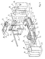
- FIGS. 1 to 4 explained in more detail.
- Figures 1 and 2 show perspective views of the transfer line with some processing units.
- 3 shows an outline of a clock unit with processing units 4 arranged on both sides of the center stand 1 on side stands 5.
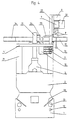
- Fig. 4 shows a vertical section through the middle part of the transfer line.
- the center stand 1 is attached to it Device base body 2 shown on which the workpieces 3 moves become.
- the processing units 4 are on the side stands 5 at least transversely to the transport direction of the workpieces. Laterally the transport path of the workpieces 3 are on the Device base body 2 vertical supports 21 arranged on which the plate 11 rests. On one long side, the supports 11 are upwards extended by the supports 22, at the top of which Outside in the direction of transport of the workpieces 3 of the cable duct 6, the Busbars 7, the fluid lines 32 for hydraulics, lubrication, Pneumatics or similar and the manifold blocks 8 between the fluid lines 32 are attached.
- the plate 11 By arranging the utilities outside on the supports 22 is the plate 11 with the attached Tensioning cylinders 19, the suction nozzle 20 and the valve hoses 23 and 24 accessible from above at any time and expandable if necessary, without the Utilities need to be dismantled.
- the shut-off valves 31 on the fluid lines 32 of FIG neighboring stations are closed so that the distributor block 8th can be removed from the fluid line 32.
- the connections the valve hoses 23 on the distributor block 8 or the control block 10 can be solved if the valves in the manifold 8 relevant station are closed, then the plate 11 preferably to be able to expand upwards.
- the plate 11 forms the upper cover of the middle tunnel, which also below from the Device base body 2 and on the side of the supports 21 attached panel 27 is formed.
- On the underside of the plate 11 is the control block 10 with the automatically operated valves 9 arranged.
- the valve hoses 23 and 24 are from above through the plate 11 out and connected to the control block 10.
- the Connection lines within the center tunnel from the control block 10 to the individual consumers of the processing station are not shown. Are in the area of transition from one plate to the next transverse to the direction of transport of the workpieces 3 branch channels 14 and 15 for Electric lines as a connection of the cable duct 6, the busbars 7 and the tap-off unit 30 with the control cabinets 16 and 17 arranged. These branch channels 14 and 15 also run in this way.
- the plates 11 usually covered both a workstation as well as an empty station. In the area of the empty station contains the plate 11 a closable opening 29 through which the Workpiece and any measuring and testing equipment in a simple Are accessible from above.
- the coolant lines for high pressure 12 and low pressure 13 are in Center stand 1 housed below the chip slide 33 and are via lines 28 attached to the side of the side stand 5 with the individual processing units 4 connected.
- the processing units 4 on the side stands 5 are covered by panels 26 e.g. out Sliding doors housed, but the area to the transport track the workpieces remain open.
- the control cabinet 16 is connected to the Power cabinet 17 via an unbranded branch channel connected.
- the cooling unit is also on the power cabinet 17 18 shown. Two clock units are over usual Connection strips 25 connected to each other.
Landscapes
- Engineering & Computer Science (AREA)
- Mechanical Engineering (AREA)
- Machine Tool Units (AREA)
- Multi-Process Working Machines And Systems (AREA)
- Feeding Of Workpieces (AREA)
- Pipeline Systems (AREA)
Description
- Einrichtungen zum Transport der Werkstücke entlang der Mittenständer,
- seitlich an den Mittenständern angeordneten Seitenständem, auf denen die Bearbeitungseinheiten verfahrbar gelagert sind und
- Versorgungseinrichtungen für die Bearbeitungseinheiten.
Außerdem werden bei der Anordnung der Platten außen an den Seiten lange Fluidleitungen zu den Verbrauchern der Bearbeitungseinheiten insbesondere zu den pneumatischen Werkzeugspannem benötigt.
Fig. 3 zeigt als Aufriß eine Takteinheit mit beidseitig des Mittenständers 1 auf Seitenständern 5 angeordneten Bearbeitungseinheiten 4.
Fig. 4 zeigt einen senkrechten Schnitt durch den mittleren Teil der Transferstraße.
- 1
- Mittenständer
- 2
- Vorrichtungsgrundkörper
- 3
- Werkstück
- 4
- Bearbeitungseinheit
- 5
- Seitenständer
- 6
- Kabelkanal
- 7
- Stromschienen
- 8
- Verteilerblock
- 9
- Ventile
- 10
- Steuerblock an 11
- 11
- Platte
- 12
- Hochdruckleitung für Kühlmittel
- 13
- Niederdruckleitung für Kühlmittel
- 14,15
- Stichkanäle für Elektroleitungen zum Schaltschrank 16
- 16
- Schaltschrank, Steuerschrank
- 17
- Schaltschrank, Leistungsschrank
- 18
- Kühlaggregat
- 19
- Spannzylinder
- 20
- Absaugstutzen
- 21
- Stützen für 11 auf 2
- 22
- Stützen für 6, 7, 8 an 11
- 23
- Ventilschläuche zwischen 8 und 10
- 24
- Ventilschläuche zwischen 19 und 10
- 25
- Verbindungsleiste zweier Takteinheiten
- 26
- Verkleidung des Seitenteils (Schiebetür, Steckblech)
- 27
- Verkleidung des Mittenteils
- 28
- Leitungen für Kühlmittel an 5
- 29
- Öffnung in 11
- 30
- Abgangskasten
- 31
- Absperrhahn
- 32
- Fluidleitungen für Hydraulik, Schmierung, Pneumatik o.ä.
- 33
- Spänerutsche
Claims (12)
- Tranferstraße für Werkzeugmaschinen zur mechanischen, spanabhebenden Bearbeitung von Werkstücken an Bearbeitungseinheiten mitdadurch gekennzeichnet, daß in unmittelbarer Nähe der Transportbahn der Werkstücke eine Platte (11) mit einem Steuerblock (10) angebracht ist, der einerseits über Ventilschläuche (23) mit einem Verteilerblock (8) und/oder direkt mit den Fluidleitungen (32) für Hydraulik, Schmierung und Pneumatik und andererseits mit den Verbrauchern der Bearbeitungseinheit verbunden ist und daß der Steuerblock (10) an der Unterseite der Platte (11) angeordnet ist, die ganz oder teilweise als Abdeckung des die Transportbahn der Werkstücke umschließenden Mittentunnels ausgebildet ist und an der gleichzeitig ein oder mehrere Spannzylinder (19) für die Spannung derWerkstücke befestigt sind.Einrichtungen zum Transport der Werkstücke entlang der Mittenständer (1),seitlich an den Mittenständem (1) angeordneten Seitenständem (5), auf denen die Bearbeitungseinheiten (4) verfahrbar gelagert sind undVersorgungseinrichtungen für die Bearbeitungseinheiten
- Transferstraße nach Anspruch 1, dadurch gekennzeichnet, daß in die Fluidleitungen(32) für jede Bearbeitungsstation als Baueinheit ein Verteilerblock (8) mit entsprechend absperrbaren Anschlüssen einsetzbar ist.
- Transferstraße nach Anspruch 1 oder 2, dadurch gekennzeichnet, daß die Platte (11) auf Stützen (21) des Vorrichtungsgrundkörpers (2) abgestützt, ein- oder mehrteilig ausgebildet und als Gesamteinrichtung oder in Einzelteilen, vorzugsweise unabhängig von den Versorgungseinrichtungen (6, 7, 8, 14, 15) ausbaubar ist.
- Transferstraße nach Anspruch 1, 2 oder 3, dadurch gekennzeichnet, daß die in Transportrichtung der Werkstücke verlaufenden Kabelkanäle (6), Stromschienen (7) und Fluidleitungen (32) für Hydraulik, Schmierung und Pneumatik an Stützen (21, 22) seitlich und/oder oberhalb des Vorrichtungsgrundkörpers (2) befestigt sind.
- Transferstraße nach einem der vorhergehenden Ansprüche, dadurch gekennzeichnet, daß die Kabelkanäle (6) und/oder die Stromschienen (7) über seitlich oder zwischen den Platten (11) verlaufende Stichkanäle (14, 15) mit mindestens einem der außen im Bereich der Enden der Seitenständer (5) angeordneten Schaltschränke (16, 17) verbunden sind.
- Transferstraße nach einem der vorhergehenden Ansprüche, dadurch gekennzeichnet, daß jede Platte (11) in Transportrichtung der Werkstücke mindestens zwei Stationen, vorzugsweise eine Arbeits- und eine Leerstation, überdeckt.
- Transferstraße nach einem der vorhergehenden Ansprüche, dadurch gekennzeichnet, daß in oder an der Platte (11) ein Abzugsstutzen (20) und/oder eine Druckentlastungsklappe zur Ableitung von bei der Bearbeitung entstehenden Emissionsgasen angeordnet ist.
- Transferstraße nach einem der vorhergehenden Ansprüche, dadurch gekennzeichnet, daß in der Platte (11) eine verschließbare Öffnung (29) zur Entnahme von Werkstücken aus dem Mittentunnel nach oben angeordnet ist.
- Transferstraße nach einem der vorhergehenden Ansprüche, dadurch gekennzeichnet, daß Hoch- und/oder Niederdruckleitungen (12, 13) für das Kühlmittel in den Mittenständer (1) integriert und/oder seitlich am Mittenständer (1) angebracht sind.
- Transferstraße nach Anspruch 9, dadurch gekennzeichnet, daß die Hoch- und/oder Niederdruckleitungen (12, 13) für das Kühlmittel über im Seitenständer (5) integrierte und/oder über ein oder beidseitig am Seitenständer (5) angebrachte Leitungen (28) mit den Bearbeitungseinheiten (4) verbunden sind.
- Transferstraße nach einem der vorhergehenden Ansprüche, dadurch gekennzeichnet, daß die Ventile für die Kühlmittelzufuhr zu den Bearbeitungseinheiten (4) über den Wasserrinnen an den äußeren Enden der Seiteneinheiten angebracht sind.
- Transferstraße nach einem der vorhergehenden Ansprüche dadurch gekennzeichnet, daßa) die in Transportrichtung der Werkstücke verlaufenden Versorgungseinrichtungen ausschließlich innerhalb oder im Bereich und/oder oberhalb des Mittenständers (1) angeordnet sind,b) die Versorgungseinrichtungen mit jeder Bearbeitungseinheiten über kurze, lösbare Verbindungsstücke verbunden sind,c) zumindest in den Fluidleitungen(32) für Hydraulik, Schmierung, Pneumatik etc. Absperreinrichtungen (31) angeordnet sind undd) zwischen den Absperreinrichtungen (31) und der Bearbeitungseinheit mindestens ein Steuerblock (10) mit Ventilen (9) angeordnet ist.
Applications Claiming Priority (5)
| Application Number | Priority Date | Filing Date | Title |
|---|---|---|---|
| DE19546030 | 1995-12-09 | ||
| DE19546030 | 1995-12-09 | ||
| DE19626581 | 1996-07-02 | ||
| DE19626581A DE19626581A1 (de) | 1995-12-09 | 1996-07-02 | Transferstraße mit Bearbeitungsstationen |
| PCT/EP1996/005443 WO1997021518A1 (de) | 1995-12-09 | 1996-12-05 | Transferstrasse mit bearbeitungsstationen |
Publications (2)
| Publication Number | Publication Date |
|---|---|
| EP1011916A2 EP1011916A2 (de) | 2000-06-28 |
| EP1011916B1 true EP1011916B1 (de) | 2001-05-09 |
Family
ID=26021113
Family Applications (1)
| Application Number | Title | Priority Date | Filing Date |
|---|---|---|---|
| EP96942359A Expired - Lifetime EP1011916B1 (de) | 1995-12-09 | 1996-12-05 | Transferstrasse mit bearbeitungsstationen |
Country Status (6)
| Country | Link |
|---|---|
| US (1) | US6098269A (de) |
| EP (1) | EP1011916B1 (de) |
| AT (1) | ATE200998T1 (de) |
| AU (1) | AU1177297A (de) |
| BR (1) | BR9611807A (de) |
| WO (1) | WO1997021518A1 (de) |
Cited By (2)
| Publication number | Priority date | Publication date | Assignee | Title |
|---|---|---|---|---|
| DE19729369C5 (de) * | 1997-07-09 | 2008-08-21 | Teamtechnik Maschinen Und Anlagen Gmbh | Autarker Bearbeitungsplatz und daraus bestehende Bearbeitungsstraße |
| CN108788885A (zh) * | 2018-06-11 | 2018-11-13 | 宁波贝克韦尔智能科技有限公司 | 一种可同时加工轴类内孔和外圆的连续上下料机床 |
Families Citing this family (9)
| Publication number | Priority date | Publication date | Assignee | Title |
|---|---|---|---|---|
| AUPQ916600A0 (en) | 2000-08-03 | 2000-08-24 | James Hardie Research Pty Limited | Automated manufactured apparatus for aluminium window/door systems |
| DE20114662U1 (de) * | 2001-09-05 | 2003-01-23 | Cooper Power Tools GmbH & Co., 73463 Westhausen | Schraubsystem |
| DE20201964U1 (de) * | 2002-02-08 | 2003-06-12 | Cooper Power Tools GmbH & Co., 73463 Westhausen | Transportsystem |
| DE102008009090B3 (de) * | 2008-02-14 | 2009-06-04 | MAG Industrial Automation Systems, LLC., Sterling Heights | Beschickungs- und Entnahme-Anlage für Werkzeug-Maschinen |
| AT510516B1 (de) * | 2010-09-21 | 2013-10-15 | Trumpf Maschinen Austria Gmbh | Fertigungszelle mit einer werkteil- transfereinrichtung und transporteinrichtung für werkteile und teileträger |
| CN102451994B (zh) * | 2010-10-25 | 2013-08-14 | 大连德新机电技术工程有限公司 | 双轴变桨电动螺栓拧紧机 |
| RU2492987C2 (ru) * | 2011-11-14 | 2013-09-20 | Открытое акционерное общество "АВТОВАЗ" | Поворотное устройство автоматической линии |
| CN203125101U (zh) * | 2012-11-19 | 2013-08-14 | 富鼎电子科技(嘉善)有限公司 | 螺丝拆卸装置 |
| US10099334B2 (en) * | 2013-09-13 | 2018-10-16 | Fuji Corporation | Machining system |
Family Cites Families (11)
| Publication number | Priority date | Publication date | Assignee | Title |
|---|---|---|---|---|
| US2668557A (en) * | 1950-03-21 | 1954-02-09 | American Tool Works Co | Conduit system for machine tools |
| US2892388A (en) * | 1951-07-24 | 1959-06-30 | Giddings & Lewis | Multiple line feed for translatable machine elements |
| DE2401503C3 (de) * | 1974-01-12 | 1978-12-21 | Cross Europa-Werk Gmbh, 7317 Wendlingen | Übergabeeinrichtung für Werkstückträger an den Übergabestationen einer Transferstraße |
| CH636550A5 (fr) * | 1978-12-27 | 1983-06-15 | Maurice Prodel | Poste de travail d'une machine pour l'assemblage et/ou l'usinage de pieces. |
| AT392050B (de) * | 1984-02-06 | 1991-01-10 | Sticht Walter | Fertigungsanlage mit mehreren einzelstationen |
| ATE128791T1 (de) * | 1988-02-26 | 1995-10-15 | Esec Sa | Verfahren und einrichtung zum bestücken von metallenen systemträgern mit elektronischen komponenten. |
| JPH04343631A (ja) * | 1991-01-25 | 1992-11-30 | Seiko Epson Corp | 部品の組付け装置 |
| DE9203125U1 (de) * | 1992-03-10 | 1992-04-23 | Berliner Werkzeugmaschinenfabrik GmbH, O-1140 Berlin | Kühlschmierstoffleitung |
| DE9208584U1 (de) * | 1992-06-22 | 1992-09-24 | Afag AG für automatische Fertigungstechnik, Aarberg | Fertigungsanlage |
| DE9208735U1 (de) * | 1992-06-30 | 1992-09-10 | Grob Werke GmbH & Co KG, 8948 Mindelheim | Transferstraße mit Bearbeitungsstationen |
| US5321874A (en) * | 1992-07-31 | 1994-06-21 | Ford Motor Company | Multi-positioner machining system |
-
1996
- 1996-12-05 AU AU11772/97A patent/AU1177297A/en not_active Abandoned
- 1996-12-05 EP EP96942359A patent/EP1011916B1/de not_active Expired - Lifetime
- 1996-12-05 WO PCT/EP1996/005443 patent/WO1997021518A1/de not_active Ceased
- 1996-12-05 BR BR9611807A patent/BR9611807A/pt not_active IP Right Cessation
- 1996-12-05 US US09/091,211 patent/US6098269A/en not_active Expired - Fee Related
- 1996-12-05 AT AT96942359T patent/ATE200998T1/de not_active IP Right Cessation
Cited By (3)
| Publication number | Priority date | Publication date | Assignee | Title |
|---|---|---|---|---|
| DE19729369C5 (de) * | 1997-07-09 | 2008-08-21 | Teamtechnik Maschinen Und Anlagen Gmbh | Autarker Bearbeitungsplatz und daraus bestehende Bearbeitungsstraße |
| CN108788885A (zh) * | 2018-06-11 | 2018-11-13 | 宁波贝克韦尔智能科技有限公司 | 一种可同时加工轴类内孔和外圆的连续上下料机床 |
| CN108788885B (zh) * | 2018-06-11 | 2020-07-10 | 宁波贝克韦尔智能科技有限公司 | 一种可同时加工轴类内孔和外圆的连续上下料机床 |
Also Published As
| Publication number | Publication date |
|---|---|
| US6098269A (en) | 2000-08-08 |
| EP1011916A2 (de) | 2000-06-28 |
| AU1177297A (en) | 1997-07-03 |
| WO1997021518A1 (de) | 1997-06-19 |
| ATE200998T1 (de) | 2001-05-15 |
| BR9611807A (pt) | 1999-02-17 |
Similar Documents
| Publication | Publication Date | Title |
|---|---|---|
| EP1747843B1 (de) | Bearbeitungsmaschine mit einem Werkstückwechsler | |
| DE19729369C2 (de) | Autarker Bearbeitungsplatz und daraus bestehende Bearbeitungsstraße | |
| AT519407B1 (de) | Bearbeitungsanlage für Platten und dergleichen und mit dieser Anlage verwirklichte Produktionslinie | |
| DE19626581A1 (de) | Transferstraße mit Bearbeitungsstationen | |
| EP1990160B1 (de) | Durchlaufbohrmaschine | |
| EP1011916A2 (de) | Transferstrasse mit bearbeitungsstationen | |
| EP2762270A1 (de) | Produktionsmaschine | |
| DE202013003108U1 (de) | Werkstückpalette an Bohr-Fräs-Bearbeitungszentren | |
| DE3507676C2 (de) | ||
| EP0901883B1 (de) | Spannvorrichtung, insbesondere Maschinenschraubstock | |
| DE102007009329A1 (de) | Bearbeitungslinie | |
| EP3524376B1 (de) | Schneidvorrichtung zur spanabhebenden bearbeitung von werkstücken | |
| DE4416486C2 (de) | Plattenaufteilanlage | |
| DE4008419C2 (de) | ||
| EP0366862A1 (de) | Härteanlage mit induktivitätsarmem Gehänge | |
| EP3738693B1 (de) | Druckgiessmaschine mit energierahmen | |
| DE102008005956B4 (de) | Bearbeitungszentrum mit Werkstückwechsler und Rüstplatz | |
| DE2020061B2 (de) | Formschließeinheit für die Spritzgießform einer Spritzgießmaschine mit Schutzschiebern | |
| DE4204860C2 (de) | Bolzenschweißgerät | |
| DE102024002708B3 (de) | Vorrichtung zum Führen von Werkzeugen auf einem Werkstück parallel zu einer Werkstückkante | |
| DE102009048768B4 (de) | Vorrichtung zum Härten eines zylindrischen Abschnitts eines Werkstücks und Verwendung einer solchen Vorrichtung | |
| WO1996007814A1 (de) | Untertägiger energiezug | |
| DE1690170C3 (de) | Kombinierte Anschlußeinrichtung für verschiedenartige Versorgungssysteme | |
| DE9205042U1 (de) | Ablage für Kühlgeräte | |
| EP3290551A1 (de) | Fahrschiene für eine wartungseinrichtung zur wartung von arbeitsstellen einer spinnmaschine sowie spinnmaschine |
Legal Events
| Date | Code | Title | Description |
|---|---|---|---|
| PUAI | Public reference made under article 153(3) epc to a published international application that has entered the european phase |
Free format text: ORIGINAL CODE: 0009012 |
|
| 17P | Request for examination filed |
Effective date: 19980522 |
|
| AK | Designated contracting states |
Kind code of ref document: A2 Designated state(s): AT BE CH DE ES FR GB IT LI NL PT SE |
|
| 17Q | First examination report despatched |
Effective date: 20000720 |
|
| GRAG | Despatch of communication of intention to grant |
Free format text: ORIGINAL CODE: EPIDOS AGRA |
|
| GRAG | Despatch of communication of intention to grant |
Free format text: ORIGINAL CODE: EPIDOS AGRA |
|
| GRAH | Despatch of communication of intention to grant a patent |
Free format text: ORIGINAL CODE: EPIDOS IGRA |
|
| RIN1 | Information on inventor provided before grant (corrected) |
Inventor name: GLOCK, WERNER Inventor name: EDLER, HELMUT Inventor name: DENKENA, BEREND Inventor name: CHMIELNICKI, SIEGMUND Inventor name: CASPER, JUERGEN Inventor name: BAYHA, THOMAS Inventor name: BALLMER, HORST Inventor name: ALBUS, WERNER |
|
| GRAH | Despatch of communication of intention to grant a patent |
Free format text: ORIGINAL CODE: EPIDOS IGRA |
|
| GRAA | (expected) grant |
Free format text: ORIGINAL CODE: 0009210 |
|
| AK | Designated contracting states |
Kind code of ref document: B1 Designated state(s): AT BE CH DE ES FR GB IT LI NL PT SE |
|
| PG25 | Lapsed in a contracting state [announced via postgrant information from national office to epo] |
Ref country code: NL Free format text: LAPSE BECAUSE OF FAILURE TO SUBMIT A TRANSLATION OF THE DESCRIPTION OR TO PAY THE FEE WITHIN THE PRESCRIBED TIME-LIMIT Effective date: 20010509 Ref country code: IT Free format text: LAPSE BECAUSE OF FAILURE TO SUBMIT A TRANSLATION OF THE DESCRIPTION OR TO PAY THE FEE WITHIN THE PRE;WARNING: LAPSES OF ITALIAN PATENTS WITH EFFECTIVE DATE BEFORE 2007 MAY HAVE OCCURRED AT ANY TIME BEFORE 2007. THE CORRECT EFFECTIVE DATE MAY BE DIFFERENT FROM THE ONE RECORDED.SCRIBED TIME-LIMIT Effective date: 20010509 Ref country code: GB Free format text: LAPSE BECAUSE OF FAILURE TO SUBMIT A TRANSLATION OF THE DESCRIPTION OR TO PAY THE FEE WITHIN THE PRESCRIBED TIME-LIMIT Effective date: 20010509 Ref country code: FR Free format text: LAPSE BECAUSE OF FAILURE TO SUBMIT A TRANSLATION OF THE DESCRIPTION OR TO PAY THE FEE WITHIN THE PRESCRIBED TIME-LIMIT Effective date: 20010509 |
|
| REF | Corresponds to: |
Ref document number: 200998 Country of ref document: AT Date of ref document: 20010515 Kind code of ref document: T |
|
| REG | Reference to a national code |
Ref country code: CH Ref legal event code: EP |
|
| REF | Corresponds to: |
Ref document number: 59606887 Country of ref document: DE Date of ref document: 20010613 |
|
| PG25 | Lapsed in a contracting state [announced via postgrant information from national office to epo] |
Ref country code: SE Free format text: LAPSE BECAUSE OF FAILURE TO SUBMIT A TRANSLATION OF THE DESCRIPTION OR TO PAY THE FEE WITHIN THE PRESCRIBED TIME-LIMIT Effective date: 20010809 Ref country code: PT Free format text: LAPSE BECAUSE OF FAILURE TO SUBMIT A TRANSLATION OF THE DESCRIPTION OR TO PAY THE FEE WITHIN THE PRESCRIBED TIME-LIMIT Effective date: 20010809 |
|
| NLV1 | Nl: lapsed or annulled due to failure to fulfill the requirements of art. 29p and 29m of the patents act | ||
| GBV | Gb: ep patent (uk) treated as always having been void in accordance with gb section 77(7)/1977 [no translation filed] |
Effective date: 20010509 |
|
| PG25 | Lapsed in a contracting state [announced via postgrant information from national office to epo] |
Ref country code: ES Free format text: LAPSE BECAUSE OF FAILURE TO SUBMIT A TRANSLATION OF THE DESCRIPTION OR TO PAY THE FEE WITHIN THE PRESCRIBED TIME-LIMIT Effective date: 20011130 |
|
| PG25 | Lapsed in a contracting state [announced via postgrant information from national office to epo] |
Ref country code: AT Free format text: LAPSE BECAUSE OF NON-PAYMENT OF DUE FEES Effective date: 20011205 |
|
| EN | Fr: translation not filed | ||
| PG25 | Lapsed in a contracting state [announced via postgrant information from national office to epo] |
Ref country code: LI Free format text: LAPSE BECAUSE OF NON-PAYMENT OF DUE FEES Effective date: 20011231 Ref country code: CH Free format text: LAPSE BECAUSE OF NON-PAYMENT OF DUE FEES Effective date: 20011231 Ref country code: BE Free format text: LAPSE BECAUSE OF NON-PAYMENT OF DUE FEES Effective date: 20011231 |
|
| PLBE | No opposition filed within time limit |
Free format text: ORIGINAL CODE: 0009261 |
|
| STAA | Information on the status of an ep patent application or granted ep patent |
Free format text: STATUS: NO OPPOSITION FILED WITHIN TIME LIMIT |
|
| 26N | No opposition filed | ||
| BERE | Be: lapsed |
Owner name: HULLER HILLE G.M.B.H. Effective date: 20011231 |
|
| REG | Reference to a national code |
Ref country code: CH Ref legal event code: PL |
|
| PGFP | Annual fee paid to national office [announced via postgrant information from national office to epo] |
Ref country code: DE Payment date: 20100217 Year of fee payment: 14 |
|
| REG | Reference to a national code |
Ref country code: DE Ref legal event code: R081 Ref document number: 59606887 Country of ref document: DE Owner name: MAG IAS GMBH, DE Free format text: FORMER OWNER: CROSS HUELLER GMBH, 71636 LUDWIGSBURG, DE Effective date: 20110223 |
|
| REG | Reference to a national code |
Ref country code: DE Ref legal event code: R119 Ref document number: 59606887 Country of ref document: DE Effective date: 20110701 |
|
| PG25 | Lapsed in a contracting state [announced via postgrant information from national office to epo] |
Ref country code: DE Free format text: LAPSE BECAUSE OF NON-PAYMENT OF DUE FEES Effective date: 20110701 |