EP1010813A1 - Drainagematte - Google Patents
Drainagematte Download PDFInfo
- Publication number
- EP1010813A1 EP1010813A1 EP99124741A EP99124741A EP1010813A1 EP 1010813 A1 EP1010813 A1 EP 1010813A1 EP 99124741 A EP99124741 A EP 99124741A EP 99124741 A EP99124741 A EP 99124741A EP 1010813 A1 EP1010813 A1 EP 1010813A1
- Authority
- EP
- European Patent Office
- Prior art keywords
- drainage mat
- drainage
- threads
- mat according
- strips
- Prior art date
- Legal status (The legal status is an assumption and is not a legal conclusion. Google has not performed a legal analysis and makes no representation as to the accuracy of the status listed.)
- Withdrawn
Links
Images

Classifications
-
- E—FIXED CONSTRUCTIONS
- E02—HYDRAULIC ENGINEERING; FOUNDATIONS; SOIL SHIFTING
- E02B—HYDRAULIC ENGINEERING
- E02B11/00—Drainage of soil, e.g. for agricultural purposes
Definitions
- the invention relates to a drainage mat for removing the surface water for horizontal, vertical or sloping surfaces, consisting of a Profile layer with an interrupted cross-section, the spaces between which flow away of the water and a fleece on the top, which punctually with the Profile layer is connected and prevents the penetration of soil.
- drainage pipes have depending on the application a diameter of 5 - 20 and more cm, providing the necessary mobility obtained in that the drainage tube is designed as a flexible tube that is at a distance has arranged annular stiffening parts.
- These are usually made of yellow plastic manufactured drainage pipes require a separate installation, because only then necessary inflow can be secured. Appropriate trenches are dug, which are then partially filled with gravel, with the drainage pipe in the Gravel is embedded. The effort involved is considerable.
- Drainage pipes are known which are as uniform and as possible ensure surface drainage of the water.
- Such drain elements exist from an interrupted cross section several mm thick, which, for example is formed by pimples.
- Such drainage mats therefore have the necessary strength and also withstand the considerable pressure that arises when the drainage mat is on material is still being deposited. This is the case, for example, if one Landfill is covered with drainage mats and then to produce a Green area soil is deposited on the mat.
- the broken cross section of the Drainage mat is used to allow the water to drain away in the spaces.
- a filter fleece can be arranged above this, which serves to keep the soil is held back by the actual mat and does not penetrate into the gaps can. At the same time, the filter fleece ensures due to its water permeability, that the excess water gets into the gaps and flows off can.
- the drainage mats are several mm thick and are relatively rigid, since they are designed to absorb significant loads. They then slip slightly on the surface. With those used for the production Plastics remain the contact areas between the drainage mat and the the surface to be covered is too smooth for sufficient grip to be achieved could.
- the drainage mats are too narrow to be able to be transported Rolls of webs rolled up, which, when subsequently laid, result in partial webs must be placed on top of each other to achieve the necessary sealing, causing wastage of material, leaks and there are significant shifts.
- the object of the invention is to create a drainage mat which guarantees good adhesion to the surface and overall this and reliably covers without the risk of leaks.
- the drainage mat on the bottom has a large number of individual points and / or threads protruding above them and that the partial overlap of at least on one outside of the drainage mat arranged two adjacent drainage mats allowing strips without profiling are.
- the threads arranged below the profile layer ensure that can no longer move the drainage mats on the ground because of the the arrangement of the threads prevailing frictional forces prevent this. Also uneven, hilly or sloping surfaces can be covered effectively. A rough, non-slip surface is created on the underside of the drainage mat, which in particular is achieved by applying the threads on the underside.
- the threads can in a technically relatively easy to implement manner, without specifying a certain structure and precision can be applied.
- the even layer may also be arranged, which, however would not have such favorable friction properties.
- the strips are advantageously formed from the same material as the profile layer itself and thus with regard to the mechanical and building physics Features a homogeneous drainage mat.
- the stripes can for example, can also be welded to the drainage mat later, more cost-effectively but it is to produce drainage mat and strips in one step.
- the invention provides that the strips of two adjacent webs of Drainage mats that enable their thermal or mechanical connection Width, preferably 5 - 10 cm.
- the strips of adjacent webs will be so placed on top of each other and then welded or otherwise connected to each other. This can be independent of the formation of the subsurface and its inclination happen. Since it is possible in principle, a strip according to the invention to be placed either on one or both sides of the drainage mat, overlap either the stripes over each other or the single stripe overlaps the neighboring one Drainage mat in the profile area.
- the simplest design of the strips according to the invention provides that the Strips have a reduced thickness and a flat surface. Furthermore, can such a strip also has a roughened surface or is otherwise profiled his.
- the threads can be in one be applied such that an additional layer is created.
- the invention provides for a particularly non-slip drainage mat before that the dots and / or threads have a rough or textured surface exhibit. Not only by the arrangement of the threads, but also by their formation and surface should improve the friction properties of the drainage mat become.
- the material used for this purpose is preferably high density polyethylene used. However, it is also possible to use other plastics for this purpose, however Polyethylene has proven to be special in terms of the required friction properties proven suitable.
- a preferred embodiment of the invention provides that the profile layer is formed by deep-drawn knobs and connecting webs.
- the profile layer is advantageously made of made of a material so that no leaks can occur.
- the deep-drawn knobs of the profile layer provide sufficient strength, so that there is also sufficient stability.
- the top of the drainage mat is designed so that the fleece is made of plastic manufactured and glued or thermally attached to the tips of the knobs is. Instead of a fleece made of plastic, you can also use a natural one Fibers produced material can be arranged.
- the threads are expediently from one to the underside of the drainage mat sprayed hot melt adhesive formed on polyolefin basis. This hot melt adhesive is first applied to the underside of the drainage mat during manufacture, then the threads.
- the threads have particularly good adhesion to the drainage mat and to the substrate.
- the invention is characterized in particular by the fact that a drainage mat created, which cannot slip under normal circumstances and one ensures a secure hold on the surface, while at the same time being reliable Coverage is given without the risk of leaks.
- a drainage mat created which cannot slip under normal circumstances and one ensures a secure hold on the surface, while at the same time being reliable Coverage is given without the risk of leaks.
- This is due to one made of polyethylene on the underside of the drainage mat Threads that significantly reduce the frictional properties of the bottom of the drainage mat improve.
- this is due to that on the outer sides of the neighboring ones Strips attached to drainage mats, which overlap each other and such are easy and safe to weld.
- FIG. 1 shows a cross-sectional view of a landfill.
- the substances 22 to be deposited upset are then covered with the drainage mat 1 according to the invention.
- the drainage mat 1 is constructed in such a way that by the top of it arranged fleece flowing water can drain through the spaces. On this way the landfill is constantly drained. Above the drainage mat 1 can Soil 20 are applied to cover the deposited substances and the Reintegrate landfill into the landscape. The upcoming in the ground 20 Thanks to the arrangement of the drainage mat 1, water cannot reach the area to be deposited Substances 22 arrive, but is removed, collected and the receiving water fed.
- the structure of the drainage mat 1 is shown in FIG. 2.
- the profile layer 4 which is formed from deep-drawn knobs 6.
- This embodiment forms the considerable advantage that the profile layer 4 consists of only one, homogeneous Material is made, which significantly reduces the risk of leaks.
- the formation of the knobs 6 results in spaces 15 through which the water discharged from the soil 20 can flow off well.
- the fleece 7 arranged in the drainage mat 1 prevents that above the drainage mat 1 located material gets into the spaces 15 and clogged and thus preventing the water from flowing out.
- This Threads 8 give the underside 3 of the drainage mat 1 an uneven and rough Structure, so that a much better frictional connection between the bottom 3 and the layers below are reached.
- the invention Drainage mat 1 not only on horizontal, but also uneven inclined or apply hilly surfaces without the risk of slipping.
- FIG. 3 Here is an excerpt from a drainage mat 1 shown in bottom view. The rough one is clearly visible Structure that is given to the underside 3 by the threads 8. Their application on the bottom 3 is also relatively simple because the threads 8 in none certain structure or orientation, but can be sprayed on without great precision can. As a result, the process for producing the embodiment according to the invention is uncomplicated.
- the polyolefin-based hot melt adhesive is melted and then sprayed on with pressure so that it is in the form of threads 8 in more random adheres to the underside 3 of the drainage mat 1 in a targeted manner.
- threads 8 are applied to the underside 3 of the drainage mat 1. Their effect could also be alternative or complementary through the application can be reached from individual points of any size.
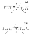
- FIG. 4 shows an average of two webs 11 and 12 arranged side by side. Until now, these had to be partially overlaid in their full thickness or very dense placed side by side. This led to leaks or unnecessary waste of material. In the arrangement of the strips 14 on the outside according to the invention 9, however, a reliable seal is achieved. The strips 14 can are now connected thermally or mechanically, leaks occur no longer, which ultimately creates a large sealing or drainage area.
- FIG. 4 shows the embodiment with one arranged on the outside 9 Strip 14, which in this case is assigned to web 11 and overlaps web 12.
- the strip 14 overlap the web 11 and the strip 14 'of the web 12. There are therefore webs 11 on both sides, 12 strips 14, 14 'arranged, which are now thermally or mechanically connected become.
Landscapes
- Engineering & Computer Science (AREA)
- General Engineering & Computer Science (AREA)
- Life Sciences & Earth Sciences (AREA)
- Agronomy & Crop Science (AREA)
- Mechanical Engineering (AREA)
- Civil Engineering (AREA)
- Structural Engineering (AREA)
- Investigation Of Foundation Soil And Reinforcement Of Foundation Soil By Compacting Or Drainage (AREA)
Abstract
Description
- Figur 1
- einen Schnitt durch eine Deponie mit Abdeckdrainage,
- Figur 2
- eine Drainagematte im Schnitt,
- Figur 3
- eine Drainagematte in Unteransicht,
- Figur 4
- zwei benachbarte Bahnen von Drainagematten mit einseitigem Streifen und
- Figur 5
- zwei benachbarte Bahnen von Drainagematten mit beidseitigem Streifen.
Claims (13)
- Drainagematte zum Abführen des Oberflächenwassers bei waagerechten, senkrechten oder schrägen Flächen, bestehend aus einer Profilschicht (4) mit unterbrochenem Querschnitt, dessen Zwischenräume (15) das Abfließen des Wassers ermöglichen und einem Vlies (7) an der Oberseite (2), welches punktuell mit der Profilschicht (4) verbunden ist und das Eindringen von Erdreich verhindert,
dadurch gekennzeichnet,
dass die Drainagematte (1) auf der Unterseite (3) eine Vielzahl einzelner, über sie vorstehende Punkte und/oder Fäden (8) aufweist. - Drainagematte zum Abführen des Oberflächenwassers bei waagerechten, senkrechten oder schrägen Flächen, bestehend aus einer Profilschicht (4) mit unterbrochenem Querschnitt, dessen Zwischenräume (15) das Abfließen des Wassers ermöglichen und einem Vlies (7) an der Oberseite (2), welches punktuell mit der Profilschicht (4) verbunden ist und das Eindringen von Erdreich verhindert,
dadurch gekennzeichnet,
dass mindestens an einer Außenseite (9) der Drainagematte (1) ein die teilweise Überlappung von zwei benachbarten Drainagematten (1) ermöglichender Streifen (14) ohne Profilgebung angeordnet ist. - Drainagematte nach Anspruch 2,
dadurch gekennzeichnet,
dass beidseitig der durch die Drainagematte (1) gebildeten Bahnen (11, 12) ein Streifen (14, 14') angeordnet ist. - Drainagematte nach einem der vorhergehenden Ansprüche,
dadurch gekennzeichnet,
dass die Streifen (14) aus dem selben Material geformt sind wie die Profilschicht (4) selbst. - Drainagematte nach einem der vorhergehenden Ansprüche,
dadurch gekennzeichnet,
dass die Streifen (14) mit der Drainagematte (1) ein Bauteil bilden. - Drainagematte nach einem der vorhergehenden Ansprüche,
dadurch gekennzeichnet,
dass die Streifen (14) zweier benachbarter Bahnen (11, 12) von Drainagematten (1) eine deren thermische oder mechanische Verbindung ermöglichende Breite aufweisen. - Drainagematte nach einem der vorhergehenden Ansprüche,
dadurch gekennzeichnet,
dass die Streifen (14) eine verringerte Dicke und eine ebene Fläche aufweisen. - Drainagematte nach einem der vorhergehenden Ansprüche,
dadurch gekennzeichnet,
dass die Menge der Punkte und/oder Fäden (8) an der Unterseite (3) der Drainagematte (1) eine schichtbildende Dicke aufweist. - Drainagematte nach einem der vorhergehenden Ansprüche,
dadurch gekennzeichnet,
dass die Punkte und/oder Fäden (8) eine rauhe oder strukturierte Oberfläche aufweisen. - Drainagematte nach einem der vorhergehenden Ansprüche,
dadurch gekennzeichnet,
dass die Profilschicht (4) durch tiefgezogene Noppen (6) und sich verbindende Stege gebildet ist. - Drainagematte nach einem der vorhergehenden Ansprüche,
dadurch gekennzeichnet,
dass das Vlies (7) aus Kunststoff hergestellt und auf die Spitzen der Noppen (6) geklebt oder thermisch daran befestigt ist. - Drainagematte nach einem der vorhergehenden Ansprüche,
dadurch gekennzeichnet,
dass die Fäden (8) von einem auf die Unterseite (3) der Drainagematte (1) aufgesprühten Schmelzkleber auf Polyolefinbasis gebildet sind. - Drainagematte nach einem der vorhergehenden Ansprüche,
dadurch gekennzeichnet,
dass die Punkte und/oder Fäden (8) auf Basis des Schmelzklebers in einer bevorzugten Menge von 20 - 60 g/m2 aufgebracht sind.
Applications Claiming Priority (4)
| Application Number | Priority Date | Filing Date | Title |
|---|---|---|---|
| DE29822222U DE29822222U1 (de) | 1998-12-14 | 1998-12-14 | Drainagematte |
| DE29822222U | 1998-12-14 | ||
| DE29900007U DE29900007U1 (de) | 1998-12-14 | 1999-01-02 | Drainagematte |
| DE29900007U | 1999-01-02 |
Publications (1)
| Publication Number | Publication Date |
|---|---|
| EP1010813A1 true EP1010813A1 (de) | 2000-06-21 |
Family
ID=26062073
Family Applications (1)
| Application Number | Title | Priority Date | Filing Date |
|---|---|---|---|
| EP99124741A Withdrawn EP1010813A1 (de) | 1998-12-14 | 1999-12-13 | Drainagematte |
Country Status (1)
| Country | Link |
|---|---|
| EP (1) | EP1010813A1 (de) |
Citations (4)
| Publication number | Priority date | Publication date | Assignee | Title |
|---|---|---|---|---|
| WO1983002790A1 (en) * | 1982-02-05 | 1983-08-18 | Gemmell, Daniel, Paterson | A drainage device |
| US4840515A (en) * | 1986-12-05 | 1989-06-20 | Mirafi, Inc. | Subterranean drain |
| US4943185A (en) * | 1989-03-03 | 1990-07-24 | Mcguckin James P | Combined drainage and waterproofing panel system for subterranean walls |
| DE4130768C1 (en) * | 1991-09-16 | 1993-04-29 | Naue-Fasertechnik Gmbh & Co Kg, 4990 Luebbecke, De | Metal reinforcement caging for hardcore under roads - uses pre-tensioned mesh under hardcore which is then tensioned and joined over laid hardcore. |
-
1999
- 1999-12-13 EP EP99124741A patent/EP1010813A1/de not_active Withdrawn
Patent Citations (4)
| Publication number | Priority date | Publication date | Assignee | Title |
|---|---|---|---|---|
| WO1983002790A1 (en) * | 1982-02-05 | 1983-08-18 | Gemmell, Daniel, Paterson | A drainage device |
| US4840515A (en) * | 1986-12-05 | 1989-06-20 | Mirafi, Inc. | Subterranean drain |
| US4943185A (en) * | 1989-03-03 | 1990-07-24 | Mcguckin James P | Combined drainage and waterproofing panel system for subterranean walls |
| DE4130768C1 (en) * | 1991-09-16 | 1993-04-29 | Naue-Fasertechnik Gmbh & Co Kg, 4990 Luebbecke, De | Metal reinforcement caging for hardcore under roads - uses pre-tensioned mesh under hardcore which is then tensioned and joined over laid hardcore. |
Similar Documents
| Publication | Publication Date | Title |
|---|---|---|
| DE202009001255U1 (de) | Schichtverbund als Träger für keramische, Stein- oder ähnliche Beläge | |
| CH661309A5 (de) | Waermedaemmplatte zur aussendaemmung und aussendrainage von gebaeudeteilen. | |
| DE8112126U1 (de) | Matte, insbesondere als Unterbauschicht für einen künstlichen Rasen | |
| DE19738488A1 (de) | Verfahren zur Herstellung einer Drainage und Drainage für Oberflächenwasser im Tunnel- und Bergbau | |
| DE202005018638U1 (de) | Drainagematerial für die Drainierung von auf Treppenstufen aufgebrachten Belägen | |
| EP0760885A1 (de) | Sollriss-fugenschiene | |
| DE4435588C1 (de) | Mehrschichtiger Bodenbelag und Verfahren zu seiner Herstellung | |
| DE19521944A1 (de) | Künstlicher Golfplatzboden für ein Grün | |
| EP2402522A2 (de) | Bau- und/oder Wärmedämmplatte sowie Wärmedämmverbundsystem mit entsprechender Platte | |
| DE2727954A1 (de) | Anlage zum be- und entwaessern von sport- und spielplaetzen sowie vegetationsflaechen aller art | |
| AT405666B (de) | Auf einen ebenen untergrund aufbringbare folie | |
| DE4130343C2 (de) | Verbundvliesmaterial und Verfahren zur Herstellung eines Verbundvliesmaterials | |
| DE10038534C2 (de) | Unterbau für Sportplätze, insbesondere Reitplätze | |
| EP1010813A1 (de) | Drainagematte | |
| DE202008007390U1 (de) | Schichtverbund als Träger für keramische, Stein- oder ähnliche Beläge | |
| AT9145U1 (de) | Sport- und/oder erholungsfläche | |
| DE19610413C2 (de) | Drainage-, Dichtungs- und/oder Wärmedämmplatte | |
| DE19851808B4 (de) | Bitumenschweißbahn | |
| DE2623321A1 (de) | Sporthallenboden | |
| EP3791032B1 (de) | Drainagematte | |
| EP1418279B1 (de) | Noppenbahn zum Abdichten von Bauwerken | |
| DE102013105920A1 (de) | Entkopplungsmatte für einen mit Belagselementen bedeckbaren Flächenbelagsaufbau | |
| EP3115193B1 (de) | Trennbahn und verfahren zur herstellung einer trennbahn | |
| DE19507040C2 (de) | Putzschichtaufbau | |
| EP2607552A1 (de) | Wasserdrainage- und Wasserrückhaltekörper, insbesondere mit Wabenstruktur |
Legal Events
| Date | Code | Title | Description |
|---|---|---|---|
| PUAI | Public reference made under article 153(3) epc to a published international application that has entered the european phase |
Free format text: ORIGINAL CODE: 0009012 |
|
| AK | Designated contracting states |
Kind code of ref document: A1 Designated state(s): AT BE CH CY DE DK ES FI FR GB GR IE IT LI LU MC NL PT SE |
|
| AX | Request for extension of the european patent |
Free format text: AL PAYMENT 20000104;LT PAYMENT 20000104;LV PAYMENT 20000104;MK PAYMENT 20000104;RO PAYMENT 20000104;SI PAYMENT 20000104 |
|
| 17P | Request for examination filed |
Effective date: 20000930 |
|
| AKX | Designation fees paid |
Free format text: AT BE CH CY DE DK ES FI FR GB GR IE IT LI LU MC NL PT SE |
|
| AXX | Extension fees paid |
Free format text: AL PAYMENT 20000104;LT PAYMENT 20000104;LV PAYMENT 20000104;MK PAYMENT 20000104;RO PAYMENT 20000104;SI PAYMENT 20000104 |
|
| 17Q | First examination report despatched |
Effective date: 20020619 |
|
| GRAH | Despatch of communication of intention to grant a patent |
Free format text: ORIGINAL CODE: EPIDOS IGRA |
|
| STAA | Information on the status of an ep patent application or granted ep patent |
Free format text: STATUS: THE APPLICATION IS DEEMED TO BE WITHDRAWN |
|
| 18D | Application deemed to be withdrawn |
Effective date: 20030417 |