EP1009561B1 - Tragvorrichtung für schüttgut, insbesondere tragbarer eimer - Google Patents
Tragvorrichtung für schüttgut, insbesondere tragbarer eimer Download PDFInfo
- Publication number
- EP1009561B1 EP1009561B1 EP98940246A EP98940246A EP1009561B1 EP 1009561 B1 EP1009561 B1 EP 1009561B1 EP 98940246 A EP98940246 A EP 98940246A EP 98940246 A EP98940246 A EP 98940246A EP 1009561 B1 EP1009561 B1 EP 1009561B1
- Authority
- EP
- European Patent Office
- Prior art keywords
- casing
- insert
- rivet
- profile
- container wall
- Prior art date
- Legal status (The legal status is an assumption and is not a legal conclusion. Google has not performed a legal analysis and makes no representation as to the accuracy of the status listed.)
- Expired - Lifetime
Links
- 239000013590 bulk material Substances 0.000 title claims 3
- 239000013013 elastic material Substances 0.000 claims description 10
- 239000000463 material Substances 0.000 claims description 9
- 239000007787 solid Substances 0.000 claims description 6
- 229920001971 elastomer Polymers 0.000 claims description 5
- 239000000806 elastomer Substances 0.000 claims description 5
- 230000002093 peripheral effect Effects 0.000 claims description 5
- 239000002184 metal Substances 0.000 claims description 4
- 238000007789 sealing Methods 0.000 claims description 3
- 239000003566 sealing material Substances 0.000 claims description 2
- 238000010276 construction Methods 0.000 claims 1
- 239000011159 matrix material Substances 0.000 claims 1
- 210000003128 head Anatomy 0.000 description 12
- 238000004519 manufacturing process Methods 0.000 description 5
- 238000000034 method Methods 0.000 description 5
- 238000003780 insertion Methods 0.000 description 2
- 230000037431 insertion Effects 0.000 description 2
- 239000007788 liquid Substances 0.000 description 2
- 239000003973 paint Substances 0.000 description 2
- 238000005452 bending Methods 0.000 description 1
- 239000007769 metal material Substances 0.000 description 1
- 238000004806 packaging method and process Methods 0.000 description 1
- 238000003825 pressing Methods 0.000 description 1
- 238000004080 punching Methods 0.000 description 1
- 230000007704 transition Effects 0.000 description 1
- 230000002792 vascular Effects 0.000 description 1
Images


Classifications
-
- B—PERFORMING OPERATIONS; TRANSPORTING
- B65—CONVEYING; PACKING; STORING; HANDLING THIN OR FILAMENTARY MATERIAL
- B65D—CONTAINERS FOR STORAGE OR TRANSPORT OF ARTICLES OR MATERIALS, e.g. BAGS, BARRELS, BOTTLES, BOXES, CANS, CARTONS, CRATES, DRUMS, JARS, TANKS, HOPPERS, FORWARDING CONTAINERS; ACCESSORIES, CLOSURES, OR FITTINGS THEREFOR; PACKAGING ELEMENTS; PACKAGES
- B65D25/00—Details of other kinds or types of rigid or semi-rigid containers
- B65D25/28—Handles
- B65D25/32—Bail handles, i.e. pivoted rigid handles of generally semi-circular shape with pivot points on two opposed sides or wall parts of the conainter
-
- B—PERFORMING OPERATIONS; TRANSPORTING
- B44—DECORATIVE ARTS
- B44D—PAINTING OR ARTISTIC DRAWING, NOT OTHERWISE PROVIDED FOR; PRESERVING PAINTINGS; SURFACE TREATMENT TO OBTAIN SPECIAL ARTISTIC SURFACE EFFECTS OR FINISHES
- B44D3/00—Accessories or implements for use in connection with painting or artistic drawing, not otherwise provided for; Methods or devices for colour determination, selection, or synthesis, e.g. use of colour tables
- B44D3/12—Paint cans; Brush holders; Containers for storing residual paint
Definitions
- the invention relates to a carrying device in the preamble of Specified claim 1.
- Such vessels are e.g. as a bucket for paints used.
- the buckets come with one for their transport and handling
- support bracket which is arranged to be movable, in particular pivotable. This is done using a peg attached to the outside of the vessel wall, the forms a bearing for a bracket.
- the bracket has a bearing eye that encloses the circumference of the pin (see e.g. FR-A-1 393 411).
- the pin is a solid body formed, the foot region is designed as a hollow rivet (US 4 039 099).
- This Known rivet attachment is a time consuming and costly process. It must First cut a hole in the vessel wall with a punch and the hole edge can be angled using a bending tool. Then the cone with the rivet shaft attached to it from the outside of the vessel wall inserted, with the rivet shaft protruding on the inner surface of the vessel wall.
- the invention has for its object a reliable support device in the The preamble of claim 1 mentioned type to develop, the inexpensive manufactured and can be easily attached to the vessel. This is according to the invention achieved by the measures listed in the characterizing part of claim 1, to whom has the following special meaning.
- the invention proposes a pin formed from two different parts before, one part of which is a rigid shell.
- This envelope is based on the Rivets off on the outer surface of the vessel wall.
- This particular peg is a assigned a separate rivet, which is supported on the inner surface of the vessel wall, the Vessel wall is pierced and anchored inside the shell. Between the rivet and the envelope of the pin, the vessel wall is clamped.
- This training of Tenon and rivet attachment can be easily made in an automatic production Integrate vessels. This is a particularly fast and inexpensive manufacture the carrying device possible.
- the invention also avoids sealing problems that arise because of Drill through the wall of the vessel using the rivet.
- the cone consists of two components nested inside one another in use, namely the outer one dimensionally stable shell also from an elastic filling inside the shell.
- the Cover has a cavity for this.
- the inner surface of this cavity can Deformation of the shank end serve when the rivet shank makes its way through the elastic filling drills.
- the rivet shaft displaces this when it deforms elastic material against the opening of this cavity. This means that one comes first particularly firm connection of the two-part pin according to the invention with the Vessel wall.
- the elastic material in the cavity ensures one Sealing the gap between the borehole in the vessel wall, the rivet shaft and the hollow of the spigot, which is why leaks at this point Security are avoided.
- the elastic material of the filling finally ensures a permanent, elastic pressure of the dimensionally stable shell on the outer surface of the Vessel wall.
- the elastic material of the filling can be between the wall of the vessel and the case can be arranged.
- the carrying device for bulk goods shown in Fig. 1 consists of a bucket trained vessel 11 and a movable support bracket 12.
- a movable support bracket 12 For this purpose are provided on the vessel wall 13 two pins 14, the articulation points 15 for the Have support bracket 12.
- the bracket 12 has at both ends of the bracket Bearing eyes 16 which a peripheral surface 24 to be described in more detail on the grasp both pins 14. This allows the bracket to be different Transfer swivel positions.
- Fig. 1 is a in solid lines "Rest position" of the bracket 12 shown.
- the wearing position is dash-dotted 12 'illustrated in Fig. 1.
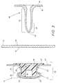
- the pin 14 has a special structure, as can be seen in FIG. 3 results.
- the pin 14 consists of a two components 21, 22 comprising preassembled unit 20.
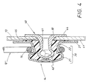
- FIG. 3 shows, on the left in the picture, the unit 20 their attachment to the vascular wall 13 shown in breakouts there and in FIG. 4 the finished mounting position of this assembly 20.
- the two components 21, 22 this assembly 20 are shown in Fig. 2 in an exploded view and have following structure.
- One component is a dimensionally stable shell 21 which has a cavity 23. He consists in the present case of a sheet metal body, one as a pivot point 15 for the above-described support bracket 12 serving neck 25, the hereinafter referred to as "sleeve neck”. At one end of this Sleeve neck 25 is a thickened head 26, which is analogous to the following "Shell head” should be called. At the opposite end is a flange 27 molded on, which is then to be referred to as the "sleeve flange". In the case of fortification, 4, the sleeve flange 27 runs parallel to the outer surface 17 of the Vessel wall 13. The cavity 23 tapers in the area of the envelope neck 25 funnel-shaped up to a narrowest cross-section 28 marked 28 according to the left picture of FIG. 2.
- the other component of the assembly 20 is one in the cavity 23 according to the left 3 filling of elastic material 30.
- this elastic filling 22 is made of an elastomer material 30, such as resilient plastic, existing insert 22 for the sleeve 21.
- This insert 22 has an axial profile 39 analogous to the envelope profile 29 of FIG. 2 this, as can be seen in the right image of FIG. 2, an insert flange 37, the covered in the case of use according to the left image of Fig. 3 by the sleeve flange 27 becomes.
- an insert neck 35 there, which in use, as shown in FIG. 3 shows, is arranged in the height region of the sleeve neck 25 and on an insert head 26 in the height range of the envelope head 25.
- the Insert head 36 compared to the narrowest cross-sectional width 28 described above Cave 23 oversized.
- the two components 21, 22 are by axial Compressing brought together in the direction of arrow 18 of FIG. 2.
- the insert head 36 is elastically deformable because of the elastomer material 30 and acts like a "male part" of a snap-type snap connection.
- the narrowed cross section 28 of the sleeve 21 acts as a die part thereof Snap connection.
- the funnel-shaped tapering of the Sleeve neck 25 serves as an insertion aid during this assembly.
- the snap state of Fig. 3 are the two components 21, 22 due to the push button connection captively connected. Therefore, the assembly 20 can still Fastening process to be described in more detail than a prefabricated combination be handled consistently.
- the assembly 20 is fastened to the vessel wall 13 as shown in FIG. 4 can be recognized by a rivet 40, the appearance of which results from FIG. 3.
- the rivet 40 is a hollow rivet with a hollow rivet shaft 41, a rivet tip 43 on one Shaft end 42 and a radial plate 44 at the other shaft end.
- the rivet 40 When fastening the rivet 40 from the inner surface 19 shown in FIG Vessel wall 13 pressed and drills its way through the wall material. It This results in a borehole 45 recognizable in FIG. 4 in the vessel wall 13 Drill tip 43 penetrates into the interior of the insert 22, the 4 is converted into the deformed shape 42 'shown there
- the elastic material 30 of the insert 22 is against the inner surface 31 repressed.
- the inner surface of the hollow profile 31 limits the space in this Deformation 42 '.
- the material 30 is also against the outer surface 17 of the Vessel wall 13 pressed and there ensures a seal between the Borehole 45 and the rivet shaft 41 resulting gap. Despite the due to Rivet fastening generated breakthrough of the vessel wall 13 is a perfect one Tightness achieved.
- the elastomer material 30 also ensures an elastic, axial connection.
- the compressed material 30 between the rivet plate 44 on the one hand and the sleeve flange 27, an axial pressure force can arise which automatically reseals. This is particularly important because after Filling the vessel 11 with liquids in the carrying position 12 'of FIG. 4 high Forces can act on the pin 14, which loosen the rivet attachment to attempt.
- the rivet plate 44 could on its in Fig. 3 marked inner surface 46 may be covered with sealing material. For that would an elastic washer is suitable.
- the articulation point 15 for the support bracket 12 is located 2 in the peripheral region 24 of the sleeve neck 25.
- the left image of Fig. 2 is located at the transition point between the shell head 26 and the Envelope neck 25 has a substantially radial shoulder 47.
- This shoulder 47 runs in the Essentially perpendicular to the dash-dotted pin axis indicated in FIG. 2 50.
- the circumferential surface 48 of the casing head 29 which can be seen in FIG. 2 is in the Essentially cylindrical. This creates between the cylinder surface 48 and the radial shoulder 47 a substantially right angle, the Angle vertex is 49.
- the envelope head is at its front end, like the left one Picture of Fig. 2 shows, provided with an axial dent 51, which in the present case arises from a molded-in hollow cone 52.
- the cone tip of this hollow cone 52 lies on the aforementioned pin axis 50.
- This shape of the sleeve 21 is created by means of the tool shown in FIG. 5. It is first made from sheet metal material 53 by punching and forming in FIG. 5 recognizable spherical intermediate 54 generated, which then in its future Sheath flange between two tool parts 55, 56 one recognizable from FIG. 5 Press is held.
- the tool part 55 has a cylindrical space 57 in which a plunger 58 axially during the pressing process in the sense of the pressure arrow 59 is mobile.
- the plunger 58 has a plunger profile 60 at its front end First, the aforementioned axial dent 51 in the spherical center of the preliminary product 54 generated, which serves as the centering of the further deformation of the intermediate 54. This crowned part of the preliminary product 54 is compressed until, as is dot-dashed indicated, the above-described special shape of the shell 21 is formed.
- the assembly 20 according to FIG. 3 can be very easily and exactly with one Process riveting device.
- This riveting device can be conveniently in turn Different operations of an automatic production of buckets 11 be incorporated.
- the result is very neatly set pins 14, the high ones Can withstand forces.
- the rivet connection is a flawless Tightness of the vessel 11 generated.
- the buckets can easily be used as Packaging containers for liquids, e.g. for paints.
- the Manufacture of such support devices 10 is therefore very inexpensive and quick to take place.
Landscapes
- Engineering & Computer Science (AREA)
- Mechanical Engineering (AREA)
- Insertion Pins And Rivets (AREA)
Description
- Fig. 1
- in Seitenansicht und teilweise im Ausbruch, die Ansicht auf die fertige Tragvorrichtung bestehend aus einem Eimer und einem Tragbügel, der in zwei Positionen, nämlich einer Ruhelage des Eimers und einer Traglage des Eimers, dargestellt ist,
- Fig. 2
- in starker Vergrößerung und im Axialschnitt, die Explosionsdarstellung der beiden Bestandteile eines Zapfens, von dem zwei in diametraler Anordnung zueinander, bei dem in Fig. 1 gezeigten Gefäß verwendet werden,
- Fig. 3
- in einem der Fig. 2 entsprechendem Axialschnitt und ebenfalls in Vergrößerung, der aus den Bestandteilen von Fig. 2 vormontierte Zapfen vor seiner Befestigung an der im Ausbruch gezeigten Gefäßwand und einem zur Befestigung des Zapfens dienenden Hohlniet,
- Fig. 4
- die in Fig. 3 gezeigten Bestandteile nach der Befestigung und,
- Fig. 5
- ein Gerät zur Vorfertigung des einen, in Fig. 2 gezeigten Bestandteils vom Zapfen.
- 10
- Tragvorrichtung
- 11
- Gefäß, Eimer
- 12
- Tragbügel (Ruheposition)
- 12'
- Trageposition von 12
- 13
- Gefäßwand
- 14
- Zapfen
- 15
- Anlenkstelle für 12 bei 14
- 16
- Lagerauge an 12
- 17
- Außenfläche von 13
- 18
- Pfeil der Schnappmontage von 22 in 21, Einsteckbewegung
- 19
- Innenfläche von 13
- 20
- Baueinheit aus 21, 22
- 21
- formfeste Hülle
- 22
- elastische Füllung, Einsatz
- 23
- Höhlung von 21
- 24
- Anlenkstelle für 12, Umfangsfläche von 22
- 25
- Hüllenhals von 21
- 26
- Hüllenkopf von 21
- 27
- Hüllenflansch von 21
- 28
- engste Querschnittsweite von 23
- 29
- Ω-förmiges Axialprofil von 21
- 30
- elastisches Material von 22, Elastomermaterial
- 31
- Hohlprofil von 23
- 32
- großer Freiraum in 20 zwischen 26, 36
- 33
- kleiner Freiraum in 20 zwischen 25, 35
- 34
- fußseitige Axialaussparung von 22
- 34'
- kopfseitige Axialaussparung von 22
- 35
- Einsatzhals von 22
- 36
- Einsatzkopf von 22
- 37
- Einsatzflansch von 22
- 38
- massiver Steg zwischen 34, 34'
- 39
- Ω-förmiges Axialprofil von 22
- 40
- Hohlniet
- 41
- Nietschaft von 40
- 42
- Schaftende (Ausgangszustand)
- 42'
- Verformungszustand von 42
- 43
- Nietspitze
- 44
- radialer Teller von 40
- 45
- Bohrloch in 13
- 46
- Tellerinnenfläche von 44
- 47
- radiale Schulter von 21 zwischen 26, 25
- 48
- zylindrischer Umfang von 26
- 49
- Winkelscheitel zwischen 48, 47
- 50
- Zapfenachse von 21 bzw. 22
- 51
- axiale Delle in 36
- 52
- Hohlkegel bei 51
- 53
- Blechmaterial für 21
- 54
- Vorprodukt von 21
- 55
- erster Werkzeugteil für 21
- 56
- zweiter Werkzeugteil für 21
- 57
- zylindrischer Raum in 55
- 58
- Stößel in 57
- 59
- Druckbewegungspfeil von 58 gegenüber 57
- 60
- Stößelprofil von 58
Claims (20)
- Tragvorrichtung für Schüttgut, insbesondere tragbarer Eimer,dadurch gekennzeichnet,bestehend aus einem das Schüttgut aufnehmenden Gefäß (11), an dessen Gefäßwand (13) wenigstens ein Zapfen (14) durch eine Nietbefestigung angebracht ist,und aus einem am Zapfen (14) angelenkten (15) Tragbügel (12), der gegenüber dem Gefäß (11) beweglich ist,dass der Zapfen (14) aus zwei ineinandersteckenden Teilen (21, 22) mit zueinander unterschiedlicher Beschaffenheit besteht, nämlichaus einer formfesten Hülle (21) mit einer Höhlung (23) einerseits und aus einer elastischen Füllung (22) in der Höhlung (23) andererseits,dass die Hülle (21) beim Nieten mit der Öffnung ihrer Höhlung (23) der Außenfläche (17) der Gefäßwand (13) zugekehrt ist, während auf der Innenfläche (19) der Gefäßwand (13) sich ein Niet (40) abstützt,dessen Nietschaft (41) die Gefäßwand (13) durchbohrt (45) und dessen stauchbares (42') Schaftende (42) im Inneren der Hülle (21) verankert ist,dass die Hülle (21) mit der Innenfläche ihrer Höhlung (23) den Raum zum Verformen (42') des Schaftendes (42) begrenzt und mit ihrer Umfangsfläche (24) die Anlenkstellen (15) für den Tragbügel (12) erzeugt,dass die Füllung (22) beim Nieten den Nietschaft (41) aufnimmt und der Nietschaft (41) das elastische Material (30) der Füllung (22) sowohl gegen die Innenfläche (31) der Höhlung (23) als auch gegen die Außenfläche (17) der Gefäßwand (13) verdrängtund dass das elastische Material (30) der Füllung (22) einen Spalt zwischen dem Bohrloch (45) und dem Nietschaft (41) abdichtet.
- Vorrichtung nach Anspruch 1, dadurch gekennzeichnet, dass die formfeste Hülle (21) aus einem Blechformkörper und die elastische Füllung aus einem vorgefertigten Einsatz (22) aus Elastomermaterial (30), wie Kunststoff, bestehen
und dass der Einsatz (22) vor dem Nieten in die Höhlung (23) der Hülle (21) bzw. des Blechformkörpers eingesteckt (18) wird und eine beim Vernieten eine vormontierte, gemeinsam zu handhabende Baueinheit (20) bildet. - Vorrichtung nach Anspruch 1 oder 2, dadurch gekennzeichnet, dass die ineinandergreifenden Bereiche der Hülle (21) einerseits und der Einsatz (22) andererseits axial profiliert (29, 39) sind und das Einsatz-Profil (39) gegenüber dem Höhlungs-Profil (31) der Hülle (21) wenigstens stellenweise überdimensioniert ist
und dass beim Ineinanderstecken (18) eine Schnappverbindung zwischen den beiden Teilen (21, 22) entsteht, die, bereits vor dem Vernieten, in der Baueinheit für einen Zusammenhalt der beiden Teile (21, 22) sorgt. - Vorrichtung nach einem oder mehreren der Ansprüche 1 bis 3, dadurch gekennzeichnet, dass die Hülle (21) - im Axialschnitt gesehen - ein Ω-förmiges Axialprofil (29) aufweist, bestehend aus
einem als Anlenkstelle für den Tragbügel dienenden Hüllenhals (25) mit einem verdickten Hüllenkopf (26) am einen Ende und einen Hüllenflansch (27) am gegenüberliegenden Ende,
wobei der Hüllenflansch (27) nach der Nietbefestigung, im Wesentlichen parallel zur Außenfläche (17) der Gefäßwand (13) verläuft. - Vorrichtung nach einem oder mehreren der Ansprüche 1 bis 4, dadurch gekennzeichnet, dass der Einsatz (22) ein zum Hüllenprofil analoges Ω-förmiges Axialprofil (39) besitzt, welches - nach dem Zusammenbau der Baueinheit (20) -
aus einem den Hüllenflansch (27) wenigstens bereichsweise überdeckenden Einsatzflansch (37), aus einem im Höhenbereich des Hüllenhalses (25) angeordneten Einsatzhals (35) und aus einem im Höhenbereich des Hüllenkopfes (26) liegenden Einsatzkopf (36) bestehen. - Vorrichtung nach Anspruch 4 oder 5, dadurch gekennzeichnet, dass - nach der Nietbefestigung der Baueinheit (20) - der Einsatzflansch (37) sandwich-artig zwischen der Gefäßwand (13) einerseits und dem Hüllenflansch (27) andererseits eingeklemmt ist
und dass das elastische Material (30) des Einsatzflansches (37) eine Abdichtung des Nietschafts (14) und/oder des Bohrlochs (45) in der Gefäßwand (13) bewirkt. - Vorrichtung nach einem oder mehreren der Ansprüche 1 bis 6, dadurch gekennzeichnet, dass der Einsatzkopf (36) gegenüber der lichten Weite der Höhlung (23) in wenigstens einer Querschnittsebene (28) des Hüllenhalses (25) überdimensioniert ist und ein elastisch verformbares Patrizenteil einer druckknopfartigen Schnappverbindung bildet,
während die verengte Querschnittsweite (28) im Hüllenhals (25) einen formfesten Matrizenteil der druckknopfartigen Schnappverbindung erzeugt. - Vorrichtung nach einem oder mehreren der Ansprüche 1 bis 7, dadurch gekennzeichnet, dass die Höhlung (23) der Hülle (21) - ausgehend vom Hüllenflansch (27) sich im Bereich des Hüllenhalses (25) trichterförmig verjüngt.
- Vorrichtung nach einem oder mehreren der Ansprüche 1 bis 8, dadurch gekennzeichnet, dass - in der zwar vormontierten aber noch nicht festgenieteten Baueinheit (20) - zwischen dem Hohlprofil (31) in der Hülle (21) einerseits und dem Umrißprofil (39) des Einsatzes (22) andererseits wenigstens stellenweise Profilabweichungen bestehen, die Freiräume (32, 33) erzeugen.
- Vorrichtung nach einem oder mehreren der Ansprüche 1 bis 9, dadurch gekennzeichnet, dass der Einsatz im Eintrittsbereich des Nietschafts (41) wenigstens eine Axialaussparung (34, 34') besitzt.
- Vorrichtung nach Anspruch 10, dadurch gekennzeichnet, dass die Axialaussparungen (34, 34') im Bereich seines Einsatzkopfes (36) und/oder im Bereich seines Einsatzflansches (37) angeordnet sind.
- Vorrichtung nach einem oder mehreren der Ansprüche 1 bis 11, dadurch gekennzeichnet, dass der Einsatz (22) wenigstens bereichsweise (38) als Massivkörper ausgebildet ist, vorzugsweise im Bereich seines Einsatzhalses (35).
- Vorrichtung nach einem oder mehreren der Ansprüche 1 bis 12, dadurch gekennzeichnet, dass der Niet aus einem Hohlniet (40) mit einem endseitigen, radialen Teller (44) besteht, und der Teller (49) sich nach der Befestigung an der Innenfläche (19) der Gefäßwand (13) abstützt.
- Vorrichtung nach Anspruch 13, dadurch gekennzeichnet, dass der Nietteller (44) auf seiner der Innenfläche (19) der Gefäßwand (13) zugekehrten Seite (46) mit Dichtungsmaterial versehen ist.
- Vorrichtung nach Anspruch 13 oder 14, dadurch gekennzeichnet, dass das Nietende zugespitzt (43) ist und sich beim Nietvorgang seinen Weg durch die Gefäßwand (13) und gegebenenfalls den Einsatz (22) bohrt (45).
- Vorrichtung nach einem oder mehreren der Anspruche 1 bis 15, dadurch gekennzeichnet, dass der Hüllenkopf (26) an seinem Stirnende eine axiale Delle (51) besitzt.
- Vorrichtung nach Anspruch 16, dadurch gekennzeichnet, dass die axiale Delle (51) als Hohlkegel (52) ausgebildet ist, dessen Kegelspitze auf der Achse (50) des Zapfens (14) liegt.
- Vorrichtung nach einem oder mehreren der Ansprüche 1 bis 17, dadurch gekennzeichnet, dass der Hüllenkopf (26) mit einer im Wesentlichen radialen Schulter (47) in den Hüllenhals (25) übergeht.
- Vorrichtung nach Anspruch 18, dadurch gekennzeichnet, dass zwischen der Umfangsfläche (48) des Hüllenkopfes (26) und der radialen Schulter (47) ein im Wesentlichen rechter Winkel besteht.
- Vorrichtung nach einem oder mehreren der Ansprüche 1 bis 19, dadurch gekennzeichnet, dass die Umfangsfläche des Hüllenkopfs (26) im Wesentlichen zylindrisch (48) ausgebildet ist und koaxial zur Zapfenachse (50) verläuft.
Applications Claiming Priority (3)
| Application Number | Priority Date | Filing Date | Title |
|---|---|---|---|
| DE19739118 | 1997-09-06 | ||
| DE19739118A DE19739118A1 (de) | 1997-09-06 | 1997-09-06 | Tragvorrichtung für Schüttgut, insbesondere tragbarer Eimer |
| PCT/EP1998/004865 WO1999012673A1 (de) | 1997-09-06 | 1998-08-05 | Tragvorrichtung für schüttgut, insbesondere tragbarer eimer |
Publications (2)
| Publication Number | Publication Date |
|---|---|
| EP1009561A1 EP1009561A1 (de) | 2000-06-21 |
| EP1009561B1 true EP1009561B1 (de) | 2002-01-09 |
Family
ID=7841474
Family Applications (1)
| Application Number | Title | Priority Date | Filing Date |
|---|---|---|---|
| EP98940246A Expired - Lifetime EP1009561B1 (de) | 1997-09-06 | 1998-08-05 | Tragvorrichtung für schüttgut, insbesondere tragbarer eimer |
Country Status (4)
| Country | Link |
|---|---|
| EP (1) | EP1009561B1 (de) |
| AU (1) | AU8862898A (de) |
| DE (2) | DE19739118A1 (de) |
| WO (1) | WO1999012673A1 (de) |
Family Cites Families (7)
| Publication number | Priority date | Publication date | Assignee | Title |
|---|---|---|---|---|
| FR961209A (de) * | 1950-05-09 | |||
| FR1355692A (fr) * | 1964-06-22 | Emballages Metalliques Imprime | Support pour anse de bidons ou récipients analogues | |
| FR674659A (fr) * | 1929-05-06 | 1930-01-31 | Successeurs De Bois Et Chassan | Perfectionnements à la fabrication des rivets tubulaires industriels |
| US3137050A (en) * | 1962-06-25 | 1964-06-16 | Patent Button Co | Fastening device |
| FR1393411A (fr) * | 1964-02-04 | 1965-03-26 | Dispositif de fixation des anses de seaux, bidons et autres récipients | |
| US4039099A (en) * | 1976-02-11 | 1977-08-02 | National Can Corporation | Securing of rivets to portable articles |
| DE3644690C1 (en) * | 1986-12-30 | 1987-08-20 | Stocko Metallwarenfab Henkels | Snap fastener |
-
1997
- 1997-09-06 DE DE19739118A patent/DE19739118A1/de not_active Withdrawn
-
1998
- 1998-08-05 WO PCT/EP1998/004865 patent/WO1999012673A1/de not_active Ceased
- 1998-08-05 EP EP98940246A patent/EP1009561B1/de not_active Expired - Lifetime
- 1998-08-05 DE DE59802853T patent/DE59802853D1/de not_active Expired - Fee Related
- 1998-08-05 AU AU88628/98A patent/AU8862898A/en not_active Abandoned
Also Published As
| Publication number | Publication date |
|---|---|
| DE19739118A1 (de) | 1999-03-11 |
| EP1009561A1 (de) | 2000-06-21 |
| DE59802853D1 (de) | 2002-02-28 |
| AU8862898A (en) | 1999-03-29 |
| WO1999012673A1 (de) | 1999-03-18 |
Similar Documents
| Publication | Publication Date | Title |
|---|---|---|
| EP1068457B1 (de) | Verfahren und werkzeug zum verbinden von bauteilen mit einer platte | |
| DE3447006C2 (de) | ||
| DE19703968B4 (de) | Gelenkanordnung | |
| DE69814647T2 (de) | Stanzniet, stanznietverbindung, nietwerkzeug und verfahren zur herstellung einer nietverbindung | |
| DE19681699C2 (de) | Selbstdurchbohrender Niet | |
| DE1803417C3 (de) | Zug- und Stoßvorrichtung für Eisenbahnwagen | |
| DE19546233A1 (de) | Stangenendlager | |
| DE1452782A1 (de) | Verfahren und Vorrichtung zum nietlosen Verbinden zweier duktiler Blechteile | |
| DE3918375A1 (de) | Druckknopfverbindung | |
| DE102014113438A1 (de) | Verfahren zum Verbinden von Blechteilen und Zusammenbauteil sowie Setzkopf und Matrize | |
| DE60308751T2 (de) | Blindniet vom Abblätterntyp | |
| EP1346160B1 (de) | Bolzenelement mit einem Schaftteil und einem Kugelkopf, Zusammenbauteil und Verfahren zur Herstellung eines solchen Bolzenelements | |
| DE1116482B (de) | Niet zum Blindnieten | |
| DE3817868A1 (de) | Dichtring | |
| DE19929377A1 (de) | Verfahren und Vorrichtung zum Verbinden aufeinanderliegender Platten | |
| DE10259369B3 (de) | Vorrichtung zum Setzen eines Stanzniets in Blech | |
| EP0433938A2 (de) | Selbststanzende Befestigungsvorrichtung für wasser- und gasdichte Stanznietverbindungen | |
| EP0588779A1 (de) | Hydraulikzylinder | |
| DE102005031916B4 (de) | Halbhohlstanzniet zum mechanischen Fügen und Verfahren zum Herstellen einer Fügeverbindung | |
| EP1377397B1 (de) | Werkzeug zum nietartigen verbinden | |
| DE102019104676A1 (de) | Tablettierstempel, Tablettieranordnung bestehend aus Oberstempel und Unterstempel und Matrize sowie ein Pressverfahren für die Tablettieranordnung | |
| EP1009561A1 (de) | Tragvorrichtung für schüttgut, insbesondere tragbarer eimer | |
| EP3610988B1 (de) | Pressvorrichtung mit zentrierter bolzenfixierung | |
| DE69507582T2 (de) | Kaltgenietetes Zapfenelement | |
| DE19949524C1 (de) | Zweiteiliger Niet |
Legal Events
| Date | Code | Title | Description |
|---|---|---|---|
| PUAI | Public reference made under article 153(3) epc to a published international application that has entered the european phase |
Free format text: ORIGINAL CODE: 0009012 |
|
| 17P | Request for examination filed |
Effective date: 19991222 |
|
| AK | Designated contracting states |
Kind code of ref document: A1 Designated state(s): DE FR GB IT |
|
| GRAG | Despatch of communication of intention to grant |
Free format text: ORIGINAL CODE: EPIDOS AGRA |
|
| GRAG | Despatch of communication of intention to grant |
Free format text: ORIGINAL CODE: EPIDOS AGRA |
|
| GRAH | Despatch of communication of intention to grant a patent |
Free format text: ORIGINAL CODE: EPIDOS IGRA |
|
| 17Q | First examination report despatched |
Effective date: 20010523 |
|
| GRAH | Despatch of communication of intention to grant a patent |
Free format text: ORIGINAL CODE: EPIDOS IGRA |
|
| GRAA | (expected) grant |
Free format text: ORIGINAL CODE: 0009210 |
|
| REG | Reference to a national code |
Ref country code: GB Ref legal event code: IF02 |
|
| AK | Designated contracting states |
Kind code of ref document: B1 Designated state(s): DE FR GB IT |
|
| REF | Corresponds to: |
Ref document number: 59802853 Country of ref document: DE Date of ref document: 20020228 |
|
| GBT | Gb: translation of ep patent filed (gb section 77(6)(a)/1977) |
Effective date: 20020406 |
|
| ET | Fr: translation filed | ||
| PLBE | No opposition filed within time limit |
Free format text: ORIGINAL CODE: 0009261 |
|
| STAA | Information on the status of an ep patent application or granted ep patent |
Free format text: STATUS: NO OPPOSITION FILED WITHIN TIME LIMIT |
|
| 26N | No opposition filed | ||
| PGFP | Annual fee paid to national office [announced via postgrant information from national office to epo] |
Ref country code: DE Payment date: 20040630 Year of fee payment: 7 |
|
| PGFP | Annual fee paid to national office [announced via postgrant information from national office to epo] |
Ref country code: GB Payment date: 20040702 Year of fee payment: 7 |
|
| PG25 | Lapsed in a contracting state [announced via postgrant information from national office to epo] |
Ref country code: IT Free format text: LAPSE BECAUSE OF NON-PAYMENT OF DUE FEES;WARNING: LAPSES OF ITALIAN PATENTS WITH EFFECTIVE DATE BEFORE 2007 MAY HAVE OCCURRED AT ANY TIME BEFORE 2007. THE CORRECT EFFECTIVE DATE MAY BE DIFFERENT FROM THE ONE RECORDED. Effective date: 20050805 Ref country code: GB Free format text: LAPSE BECAUSE OF NON-PAYMENT OF DUE FEES Effective date: 20050805 |
|
| PG25 | Lapsed in a contracting state [announced via postgrant information from national office to epo] |
Ref country code: DE Free format text: LAPSE BECAUSE OF NON-PAYMENT OF DUE FEES Effective date: 20060301 |
|
| GBPC | Gb: european patent ceased through non-payment of renewal fee |
Effective date: 20050805 |
|
| PGFP | Annual fee paid to national office [announced via postgrant information from national office to epo] |
Ref country code: FR Payment date: 20080707 Year of fee payment: 11 |
|
| REG | Reference to a national code |
Ref country code: FR Ref legal event code: ST Effective date: 20100430 |
|
| PG25 | Lapsed in a contracting state [announced via postgrant information from national office to epo] |
Ref country code: FR Free format text: LAPSE BECAUSE OF NON-PAYMENT OF DUE FEES Effective date: 20090831 |