EP1007378B1 - Sculpture de bande de roulement et procede de fabrication - Google Patents
Sculpture de bande de roulement et procede de fabrication Download PDFInfo
- Publication number
- EP1007378B1 EP1007378B1 EP98906920A EP98906920A EP1007378B1 EP 1007378 B1 EP1007378 B1 EP 1007378B1 EP 98906920 A EP98906920 A EP 98906920A EP 98906920 A EP98906920 A EP 98906920A EP 1007378 B1 EP1007378 B1 EP 1007378B1
- Authority
- EP
- European Patent Office
- Prior art keywords
- tread
- cutouts
- cutout
- walls
- tyre
- Prior art date
- Legal status (The legal status is an assumption and is not a legal conclusion. Google has not performed a legal analysis and makes no representation as to the accuracy of the status listed.)
- Expired - Lifetime
Links
- 238000000034 method Methods 0.000 title claims description 23
- 229920001971 elastomer Polymers 0.000 claims abstract description 61
- 238000004519 manufacturing process Methods 0.000 claims abstract description 22
- 239000000463 material Substances 0.000 claims description 29
- 238000004073 vulcanization Methods 0.000 claims description 26
- 238000000465 moulding Methods 0.000 claims description 15
- 230000007423 decrease Effects 0.000 claims description 8
- 238000003780 insertion Methods 0.000 claims description 5
- 230000037431 insertion Effects 0.000 claims description 5
- 239000012530 fluid Substances 0.000 claims description 4
- 238000002844 melting Methods 0.000 claims description 4
- 230000008018 melting Effects 0.000 claims description 4
- 238000005299 abrasion Methods 0.000 claims description 3
- 239000004744 fabric Substances 0.000 claims description 3
- 238000007664 blowing Methods 0.000 claims description 2
- 238000009826 distribution Methods 0.000 claims description 2
- 238000000227 grinding Methods 0.000 claims description 2
- 229920001131 Pulp (paper) Polymers 0.000 claims 2
- 239000002759 woven fabric Substances 0.000 claims 1
- 238000005096 rolling process Methods 0.000 abstract description 48
- 241000913081 Scoliopteryx libatrix Species 0.000 description 24
- 239000011229 interlayer Substances 0.000 description 13
- 239000000203 mixture Substances 0.000 description 12
- 125000006850 spacer group Chemical group 0.000 description 12
- 239000010410 layer Substances 0.000 description 11
- 238000012360 testing method Methods 0.000 description 11
- 230000008569 process Effects 0.000 description 10
- XLYOFNOQVPJJNP-UHFFFAOYSA-N water Substances O XLYOFNOQVPJJNP-UHFFFAOYSA-N 0.000 description 9
- 230000000694 effects Effects 0.000 description 7
- 150000001875 compounds Chemical class 0.000 description 4
- 230000006872 improvement Effects 0.000 description 4
- 230000008901 benefit Effects 0.000 description 3
- 238000005520 cutting process Methods 0.000 description 3
- 230000009467 reduction Effects 0.000 description 3
- 230000009471 action Effects 0.000 description 2
- 239000000956 alloy Substances 0.000 description 2
- 229910045601 alloy Inorganic materials 0.000 description 2
- 244000043261 Hevea brasiliensis Species 0.000 description 1
- 230000002159 abnormal effect Effects 0.000 description 1
- 230000004075 alteration Effects 0.000 description 1
- 238000013459 approach Methods 0.000 description 1
- 238000005452 bending Methods 0.000 description 1
- 230000009286 beneficial effect Effects 0.000 description 1
- 239000011248 coating agent Substances 0.000 description 1
- 238000000576 coating method Methods 0.000 description 1
- 230000000295 complement effect Effects 0.000 description 1
- 239000000470 constituent Substances 0.000 description 1
- 125000004122 cyclic group Chemical group 0.000 description 1
- 230000000593 degrading effect Effects 0.000 description 1
- 230000002349 favourable effect Effects 0.000 description 1
- 238000007373 indentation Methods 0.000 description 1
- 238000009434 installation Methods 0.000 description 1
- 230000001788 irregular Effects 0.000 description 1
- 238000003698 laser cutting Methods 0.000 description 1
- 230000002045 lasting effect Effects 0.000 description 1
- 230000004807 localization Effects 0.000 description 1
- 230000014759 maintenance of location Effects 0.000 description 1
- 238000005259 measurement Methods 0.000 description 1
- 239000002184 metal Substances 0.000 description 1
- 229920003052 natural elastomer Polymers 0.000 description 1
- 229920001194 natural rubber Polymers 0.000 description 1
- 230000010355 oscillation Effects 0.000 description 1
- 238000004080 punching Methods 0.000 description 1
- 238000007493 shaping process Methods 0.000 description 1
- 238000004088 simulation Methods 0.000 description 1
- 239000004575 stone Substances 0.000 description 1
Images


Classifications
-
- B—PERFORMING OPERATIONS; TRANSPORTING
- B60—VEHICLES IN GENERAL
- B60C—VEHICLE TYRES; TYRE INFLATION; TYRE CHANGING; CONNECTING VALVES TO INFLATABLE ELASTIC BODIES IN GENERAL; DEVICES OR ARRANGEMENTS RELATED TO TYRES
- B60C11/00—Tyre tread bands; Tread patterns; Anti-skid inserts
- B60C11/03—Tread patterns
- B60C11/04—Tread patterns in which the raised area of the pattern consists only of continuous circumferential ribs, e.g. zig-zag
-
- B—PERFORMING OPERATIONS; TRANSPORTING
- B60—VEHICLES IN GENERAL
- B60C—VEHICLE TYRES; TYRE INFLATION; TYRE CHANGING; CONNECTING VALVES TO INFLATABLE ELASTIC BODIES IN GENERAL; DEVICES OR ARRANGEMENTS RELATED TO TYRES
- B60C11/00—Tyre tread bands; Tread patterns; Anti-skid inserts
- B60C11/03—Tread patterns
- B60C11/13—Tread patterns characterised by the groove cross-section, e.g. for buttressing or preventing stone-trapping
- B60C11/1369—Tie bars for linking block elements and bridging the groove
-
- B—PERFORMING OPERATIONS; TRANSPORTING
- B29—WORKING OF PLASTICS; WORKING OF SUBSTANCES IN A PLASTIC STATE IN GENERAL
- B29D—PRODUCING PARTICULAR ARTICLES FROM PLASTICS OR FROM SUBSTANCES IN A PLASTIC STATE
- B29D30/00—Producing pneumatic or solid tyres or parts thereof
- B29D30/06—Pneumatic tyres or parts thereof (e.g. produced by casting, moulding, compression moulding, injection moulding, centrifugal casting)
- B29D30/52—Unvulcanised treads, e.g. on used tyres; Retreading
-
- B—PERFORMING OPERATIONS; TRANSPORTING
- B60—VEHICLES IN GENERAL
- B60C—VEHICLE TYRES; TYRE INFLATION; TYRE CHANGING; CONNECTING VALVES TO INFLATABLE ELASTIC BODIES IN GENERAL; DEVICES OR ARRANGEMENTS RELATED TO TYRES
- B60C11/00—Tyre tread bands; Tread patterns; Anti-skid inserts
- B60C11/03—Tread patterns
- B60C11/12—Tread patterns characterised by the use of narrow slits or incisions, e.g. sipes
- B60C11/1259—Depth of the sipe
- B60C11/1263—Depth of the sipe different within the same sipe
-
- B—PERFORMING OPERATIONS; TRANSPORTING
- B60—VEHICLES IN GENERAL
- B60C—VEHICLE TYRES; TYRE INFLATION; TYRE CHANGING; CONNECTING VALVES TO INFLATABLE ELASTIC BODIES IN GENERAL; DEVICES OR ARRANGEMENTS RELATED TO TYRES
- B60C11/00—Tyre tread bands; Tread patterns; Anti-skid inserts
- B60C11/03—Tread patterns
- B60C11/13—Tread patterns characterised by the groove cross-section, e.g. for buttressing or preventing stone-trapping
-
- Y—GENERAL TAGGING OF NEW TECHNOLOGICAL DEVELOPMENTS; GENERAL TAGGING OF CROSS-SECTIONAL TECHNOLOGIES SPANNING OVER SEVERAL SECTIONS OF THE IPC; TECHNICAL SUBJECTS COVERED BY FORMER USPC CROSS-REFERENCE ART COLLECTIONS [XRACs] AND DIGESTS
- Y10—TECHNICAL SUBJECTS COVERED BY FORMER USPC
- Y10S—TECHNICAL SUBJECTS COVERED BY FORMER USPC CROSS-REFERENCE ART COLLECTIONS [XRACs] AND DIGESTS
- Y10S152/00—Resilient tires and wheels
- Y10S152/03—Slits in threads
Definitions
- the invention relates to treads intended for the manufacture of new tires or retreading tires, and in particular treads for said strips comprising a large number of cutouts occurring under the form of grooves and / or incisions. It also relates to a manufacturing process allowing such bands to be produced.
- adhesion we mean both grip characteristics of the tire in the transverse direction to the movement of the vehicle (cornering) than that of the tire in the direction longitudinal to the movement of the vehicle (possibility of transmitting a force to the ground brake or motor).
- this strip In order to increase the grip potential of a tread of a tire rolling on a road coated with water, it is known to provide this strip of a sculpture formed by a plurality of cutouts made more or less deep into said strip, said cutouts opening onto the surface of said strip strip in contact with the road (this surface is called the rolling surface).
- Certain cuts can lead to at least one other cut.
- the trace of a cut on the tread surface of a tread follows a profile geometric mean determined as the geometric profile located at a distance average of the edges formed by the walls of said cutout on the surface of rolling.
- the middle axis of the trace of a cut on the running surface corresponds to the line of least squares of the distances of the points of the mean profile of the trace of said cut.
- tread stiffness means the stiffness of the tread under the actions combined compressive and shear forces in the region affected by contact with the road. Jointly, the presence of numerous cutouts forming water drainage channels induces a noise level when driving on dry roads which is now considered a nuisance that we want to reduce as much as possible particularly on newly designed vehicles. This rolling noise is amplified by the cyclic movements of closing and opening of the cutouts associated with the friction of the walls of said cutouts when they are closed.
- patent FR 1 028 978 a solution is proposed to this problem consisting in providing the tread with a plurality of circumferential incisions of shallow depth on the tread surface of the new band so as to increase the flexibility of said strip only in the vicinity of the running surface.
- the tire being intended, once mounted on a vehicle, to ensure good performance throughout the life of said tire (i.e. until the wear of its tread corresponding at least to the legal level allowed) it it is necessary to provide a tread whose tread ensures the durability of grip performance on wet surfaces.
- EP-A-0 342 908 which is a document of the state of the art relevant prior, describes a tread whose characteristics correspond to those of the preamble of claim 1.
- the object of the present invention is to develop a tread for tire which combines both a very good level of grip on wet roads and on dry roads with low noise emission when driving in new condition and during minus a large part of the life of said strip.
- one of the objectives of the invention is to control the evolution of performance with wear of the tread.
- a tread of thickness E made of a rubber mixture, intended to be placed radially outside a tire, said strip being provided with a tread surface intended to come into contact. with the road while the tire is running.
- the tread is provided with a large number of cutouts so that a plurality of cutouts are affected by the area of contact of the tire with the road.
- Each cutout is defined by the space delimited mainly between two facing walls l 'from one another, said walls being perpendicular to or oblique with respect to the running surface, and each cut has a depth at most equal to the thickness E of the tread, the depth of said cut being measured as the distance, in a radial direction, of the points of the contour of said cutout furthest from the running surface of the new tire with respect to said surface.
- two main walls of at least one cutout located in the part of the tread affected by the crushing of the tire on the ground while running are connected by at least one rubber connecting element.
- S E the total connection surface on each of the walls of said cut-out equal either to the total intersection surface of the connection element in the case of a single element or to the sum of the intersection surfaces of all the connecting elements in the case of several elements and S T the total area of each of the main walls of said cutout.
- the geometric contour L of minimum length and enveloping the total connection surface S E on this wall corresponds to the contour which can be traced on said wall so as to envelop the whole of the total connection surface formed by the intersection surfaces of all the elements for connection with said wall.
- a cutout being defined as the continuous space delimited by at least two main walls facing each other, the presence of at least one connecting element between said walls, according to the invention, does not break the continuity of this space and this regardless of the level of wear of the tread comprising such a cutout.
- the effect on the adhesion and noise performance is all the more more significant than a greater number of cutouts forming the sculpture of a band tire bearings are provided with at least one connecting element rubber so as to obtain both a remarkable performance in adhesion without however degrading the level of performance in road noise.
- each surface S G delimited by the geometric contour L of minimum length and enveloping the total bonding surface S E on a main wall of a cutout is at least equal to 15% of the surface of the corresponding wall S T.
- the total connecting surface S E on at least one main wall of at least one cutout is at most equal to 80% of the surface of the corresponding wall S T , so as to maintain a cutout volume giving the strip of sufficient grip characteristics.
- a sculpture according to the invention can combine both a plurality cutouts provided with at least one connecting element with a plurality of cutouts without a connecting element, the proportion between said cutouts may for example be a function of the type of tire comprising said tread.
- the Applicant has surprisingly obtained very good rolling results with tires provided with a tread of thickness E, provided with a plurality of cutouts oriented almost in the same direction, each of said cutouts being defined by the space defined mainly between two walls facing each other, said walls being perpendicular to or oblique with respect to the rolling surface, and said cutouts having a depth h .
- depth h of a cut is meant the maximum radial distance measured between the edge of the cut closest to the running surface of the tread in new condition and the point (s) of the walls. of the cutout the farthest radially from said rolling surface. This depth h represents the maximum radial distance existing between the points radially furthest from the walls of a cutout and is at most equal to the thickness E of the tread.
- connection rate T P is less than about 0.10, the objective cannot be achieved because the connection elements do not provide enough rigidity and cannot sufficiently block the movements of the walls of the cut-out to which they are linked; preferentially, the rate of binding T P is greater than 0.25.
- active edge length of a tread of a pneumatic we mean the sum of the lengths of all the rubber edges in contact with the road in the footprint and for a level of tread wear given.
- the value of the bond rate T P S P / S T , evaluated for different wear levels of the tread decreases in a substantially regular manner with the wear of the tire, at least from a predetermined partial level of wear, S P representing, on one of the walls of said cutout, the connecting surface remaining after partial wear of the tread and S T representing the total remaining surface of said wall corresponding to the same partial level of wear of the tread.
- the effect of the connecting elements on the rigidity is maximum when the tread is new but gradually decreases with the increase in the rigidity of said strip resulting from wear.
- the draining power of the sculpture according to the invention is to say its capacity to evacuate the water present on the road, is sufficient and that whatever the level of tread wear, which is a particularly advantageous interesting for the user.
- the active edge length of the sculpture in the imprint corresponding to each level of wear is preferably defined as being at least equal to 50% of the active edge length on the running surface of the tread in new condition.
- the tread retains sufficient shear and bending rigidity when it is subjected to contact forces and this despite the presence of a very large number of cutouts, it is advisable to arrange the element (s) (S) connecting each of said cutouts so that the distance between the edge closest to the rolling surface in new condition and the points of the contour of the intersection surface of said element on said wall is at most equal to 60% of the height h of the cutout and preferably between 40% and 60% .
- Another significant improvement in the tread pattern according to the invention consists in making a plurality of cutouts provided with a number important connecting elements distributed fairly evenly in each of the cuts so as to ensure good regularity of the effect induced on the rigidity of the rubber elements delimited by the walls of the cutout.
- This tread gives the tire performance particularly homogeneous and regular whatever the degree of wear of said strip.
- Another object of the invention is to propose a method of manufacturing a strip bearing provided with a plurality of cutouts, said cutouts being provided at least one connecting element. It is clear that the usual methods of molding of the cutouts are not suitable for making such sculptures so easy and with sufficient precision. Indeed, having at least one element of connection under the running surface of the tread leads to an impossibility for demolding said strip when a conventional molding process is used and using metal blades to mold incisions.
- this tread can be produced in the form of a strip of predetermined length or in the form of a closed ring intended to be placed radially outside the tire blank during its manufacture or on a tire being retreaded.
- a variant of the process which has just been described may consist in carrying out steps a) to c) and to place the strip of unvulcanized and unmolded gum on a blank of pneumatic before proceeding to the molding and vulcanization of the assembly tire and strip thus assembled.
- this method consisting of inserting spacers in a rubber band, can also be applied in the case of the manufacture of a rubber band bearing comprising a plurality of tabs without hole for molding a plurality incisions with no connecting elements.
- the material composing the spacers and filling the cutouts provided with at least one connecting element is chosen so that it can be eliminated at least partially, i.e. at least close to the rolling surface in new condition, and gradually during taxiing to permanently maintain a long length edges.
- pulp is a filling material which is particularly suitable for this use, because this material is characterized by very low cohesion when it is in the presence of water for a sufficient period of time and therefore presents the advantage of being able to be eliminated progressively during the rolling of the tire or else of being able to be eliminated after being placed in the presence of water and before any rolling, and this all the more easily if the cutouts provided with at least one element of connection have a thickness of at least 0.4 mm.
- a variant of this process consists in choosing as the material composing the inserts a material whose melting point is sufficiently close to the vulcanization temperature of said strip so as to become fluid only towards the end of the duration of said vulcanization, taking into account the gradual rise in temperature of the rubber constituting said strip, so as to allow removal of said filling material, for example by suction or by blowing after vulcanization of said strip.
- the filling material is a alloy with a low melting point offering the advantage of being rigid during the shaping of the strip and during the vulcanization phase before becoming fluid at the end of the vulcanization of the strip so as to allow the removal of said alloy and possibly recycle it for similar use.
- the process which has just been described can also be followed by a grinding operation. almost exclusively affecting the surface of the new tread intended to make very clearly appear a plurality of edges on the rolling surface of said bandaged.
- Another way to get a good surface finish right out of the mold can consist in placing all of the cutouts provided with at least one bond under the tread surface and to mold said tread in a mold comprising a plurality of relief elements intended to mold a plurality of cutouts on the running surface and whose depth is slightly greater than the smallest of the distances separating the cutouts provided with at least one connecting element of the running surface. In this way, the tread in wearing out will gradually reveal a plurality of indentations below the surface of rolling of said new strip.
- the tread 1 partially shown in the direction of its length in FIG. 1 has a thickness E and a width W.
- One of the external walls of said strip is intended to constitute the tread surface 2 of a tire provided with said strip ; this tire can either be a new tire or a refurbished tire, that is to say a tire which has rolled until its tread has worn out, then requiring the installation of a new tread.
- a plurality of cutouts 3, 4 are made in the strip 1 so as to extend over the entire width W of said strip 1 .
- the cutout 3 is delimited by two main flat walls 5, 6 perpendicular to the rolling surface 2 and distant from each other by an average distance e equal to the width of the cutout 3 .
- the two walls 5, 6 delimiting the cutout 3 are connected to the radially innermost points 8 of the cutout relative to the rolling surface 2 .
- the intersection of the walls 5, 6 with the rolling surface 2 determines rubber edges 51 and 61 respectively, one function of which is to cut the film of water which may exist between the strip and the road.
- the cutout 3 is provided with five rubber connecting elements 7 which connect the walls 5 and 6 of said cutout, said connecting elements making it possible to keep said walls at an almost constant distance, avoiding both opening and closing of the cutout 3 .
- Figure 2 is shown a cross section of the tread 1 of Figure 1 made along the wall 6 of the cutout 3. It can be seen there, distributed fairly uniformly on the wall 6 , the intersection surfaces 71 , 72, 73, 74, 75 of the connecting elements 7 with the wall 6, the sum of said surfaces constituting the total intersection surface S E. In the present case, all the connecting elements have their intersection surfaces 71, 72, 73, 74, 75 entirely situated under the rolling surface 2 and at a radial distance from said surface less than the depth h of the cutout. .
- connection surface S E is at most equal to 80% of the surface S G delimited by the geometric contour L (in dotted lines) of minimum length constructed on the wall 6 and enveloping all the intersection surfaces 71 , 72, 73, 74, 75 of the connecting elements 7 with the wall 6 .
- the main walls of the cutouts can be flat or curved.
- the tread comprises a plurality of cutouts provided with at least one connection element and each surface S G , delimited by the geometric contour L of minimum length and enveloping the total connection surface S E on a wall of the cutout, is at least equal to 15% of the surface of the corresponding wall S T.
- the relative position of the connecting elements of the same cutout is determined so as to maintain for said cutout a large active edge length for come into contact with the ground and this regardless of the level of wear of the strip of rolling.
- Figure 3 shows the schematic section of a rib of a tread 1 made along a wall 9 of a cutout provided with a single connecting element 10 s' extending between the main walls delimiting said cutout.
- This element 10 consists of two branches 101, 102 oriented in the direction of the width of the incision and connected together by a third branch 103 oriented in the direction of the thickness of the strip.
- the contour L drawn in dotted lines corresponds to the contour of minimum length enveloping the total connection surface of the single element and passing through the ends of the branches 101 and 102 .
- An alternative embodiment consists in extending the branch 103 connecting the branches 101 and 102 to the rolling surface 2 , thereby creating a single volume corresponding to the cutout.
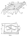
- FIG. 4 partially represents a tread 11 of a tire comprising incisions oriented in the circumferential direction and incisions oriented in the transverse direction, each of said incisions being provided with connecting elements and opening onto the rolling surface 112 of said strip.
- the tread 11 is axially divided into three annular regions denoted I, II, III, the middle region II being separated from the two edge regions I and III by grooves 12 and 13 oriented circumferentially.
- the middle part II there is provided in the middle part II a plurality of small width incisions 14 oriented essentially transversely, said incisions 14 emerging on each side of part II in the grooves 12 and 13.
- edge portions I and III there is provided at least one incision 15 oriented essentially in the circumferential direction. All the transverse orientation incisions 14 and the circumferential incisions 15 are provided with a plurality of connecting elements 141 and 151 respectively connecting the main walls forming said incisions.
- oriented essentially transversely it is meant that the mean axes of the traces of the incisions on the running surface 112 form with the transverse direction of the tread an angle at most equal to 45 °.
- oriented essentially circumferentially it is meant that the mean axes of the traces of the incisions on the running surface make with the transverse direction of the tread an angle at least equal to 75 ° and at most equal to 90 ° .
- the average axis of the trace of a cut on the running surface of a tread corresponds to the average direction evaluated between the points of the edges of said cut on the running surface using a method of least squares of the distances.
- connecting elements also connecting the walls delimiting the circumferential grooves separating part II from parts I and III.
- At least one connecting element of a cutout appears on the rolling surface and decreases the lengths of the edges 145, 146 correspondingly formed by each of the main walls of said cutout. with the running surface 2 .
- each connecting element 141 between a first main wall 142 and a second main wall 143 of the cutout 14 so that said element makes, with the perpendicular to the running surface of the new tread, an angle different from 90 ° and preferably between 30 ° and 70 ° .
- connecting elements arrive at the running surface after wear in a more or less offset manner makes it possible to permanently maintain (that is to say throughout the duration of use of the tire) a large length of edges in the region of the running surface affected by contact with the road and makes it possible to achieve favorable interference both on wear (this avoids the appearance of abnormal wear, that is to say localized) and on noise of rolling.
- a comparable result is obtained by making a single continuous cut and oriented at an angle close to 90 ° with the transverse direction so that the mean axis of the trace of the cut on the rolling surface forms a helix; in fact, everything takes place in the zone of contact with the road as if the strip were provided with a plurality of cutouts almost oriented in the circumferential direction.
- the cutouts provided with at least one connecting element can be perpendicular to the running surface or at least part of these, with the direction perpendicular to the running surface of the tread in new condition , an average angle at most equal to 20 ° so as to increase the efficiency of the rubber edges in certain uses so as to be able to better transmit a motor or braking force depending on the direction of orientation chosen for the inclination of said cutout.
- FIG. 6 represents, seen in a cross section, a wall of a cutout provided with connecting elements 7 arranged in rows almost parallel to the rolling surface 2; the number of connecting elements 7 per row increasing as one approaches the running surface 2 .
- Figure 7 shows an advantageous arrangement in terms of connecting the main walls of the same cut of a tread.
- a plurality of intersection surfaces 76 of connecting elements with said wall so that the density of connecting elements is relatively high (it i.e. there are a large number of elements per wall surface).
- the surface S G delimited by the contour L of minimum length and enveloping all the surfaces of intersection of the connection elements is approximately 90% of the total surface of the wall 66 while the connection surface S E represents only 40% of the total surface.
- An optimum effect on the rigidity of the strip is achieved when the connecting elements are regularly distributed on the walls of each cut.
- FIG. 9 schematically represents two types of tread pattern tested.
- FIG. 9-A corresponds to variant A of a tread 18 comprising a plurality of incisions 21 of width 0.1 mm, oriented transversely and spaced circumferentially by an average pitch p of 15 mm; this variant further comprises three circumferential grooves 19 of width 5 mm which axially divide the tread into four parts, each of said parts being further divided in two by a circumferential incision 20 of width 2 mm. All cutouts have the same depth equal to 13.5 mm.
- FIG. 9-A corresponds to variant A of a tread 18 comprising a plurality of incisions 21 of width 0.1 mm, oriented transversely and spaced circumferentially by an average pitch p of 15 mm; this variant further comprises three circumferential grooves 19 of width 5 mm which axially divide the tread into four parts, each of said parts being further divided in two by a circumferential incision 20 of width 2 mm. All cutouts have the same depth
- variant B of a tread 22 comprising a plurality of incisions 25 of width 1 mm oriented in a direction making an average angle of 15 ° with the transverse direction of the tire and spaced apart others with an average pitch p of 10 mm;
- this variant B further comprises two grooves 23 of corrugated and essentially circumferential shape 19 of width 10 mm which axially divide the tread into three parts, each of said parts being further divided in two by a circumferential incision 24 of width 2 mm, said incisions following the same profile as the grooves. All the cutouts of the two variants A and B have the same depth and equal on average to 13.5 mm.
- Variants A and B were produced in the following manner: after having cut, according to the tracings of the desired incisions, a strip of unvulcanized rubber of appropriate width and length, a number equal to the number of incisions and of equivalent dimensions, dividers in sheets of paper 0.1 mm thick for variant A and in sheets of cardboard 1 mm thick for variant B. Each insert is then cut so as to create a plurality of orifices whose shape corresponds to the shape of the sections of the connecting elements of the incisions.
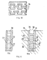
- FIG. 10 shows such an insert 16 provided with a plurality of orifices 17 of almost rectangular shape; these 2x5 mm orifices can be obtained, for example, by means of a laser cutting process or by punching. Then, these spacers 16 are put in place in the cuts made in the unvulcanized tread
- This tread is then placed on a tire blank not vulcanized before being molded with the tire in a vulcanization mold.
- the rubber of the strip passes through the inserts at the locations of the orifices to form the connecting elements of the cutouts, said cutouts being filled with the material of the spacers.
- the circumferential grooves and incisions devoid of connection were made by cutting after manufacturing the tires comprising the treads.
- the additional grooves and incisions can be produced by the process according to the invention.
- the tires chosen were heavyweight tires of size 215/75 R 17.5 , the incisions of which had connecting elements had a connection rate T P equal to 45% and for which the ratios S I / O T and S I / O G were 45% and 40% respectively.
- the notching rates of the rolling surfaces in new condition of the two variants A and B were 15% and 18% respectively (by rate of notching, one understands the ratio between the surface of the cutouts on the rolling surface and the total surface of said rolling surface).
- Grip tests were carried out with a heavy goods vehicle equipped with an additional wheel intended for measurements, said wheel being fitted with a tire according to variant A or according to variant B.
- the appearance of the tire sliding relative to the road is determined for a given speed and under the action of a determined braking force; this test is carried out on a test track having a smooth coating and on which is present a layer of water with a thickness of approximately 1.5 mm.
- a tire of type XZE, of the same dimension and having a cut rate of 18% was taken as a reference base.
- the notching rates of variants A and B are comparable to that of the tire chosen as a reference.
- the results of the grip tests showed that, compared to the reference tire, the tires of variant A were better than the reference tires by around 15% , while the tires of variant B were very at least 30% higher than the reference tires .
- the difference in performance between variants A and B can be partly explained by the difference in width of the incisions.
- the tread according to the invention and the method of manufacturing such a strip make it possible to obtain, with a low rate of notching, that is to say a ratio between the surface corresponding to the cutouts and the total surface of said strip intended to be in contact with the ground, a performance at least equivalent to a strip of usual bearing with a higher rate of notching; the large number of edges of rubber, combined with the fact that the stiffness of the tread is not affected by significantly compensates for the gap in the notch rates.
- connecting elements in the cutouts allows maintain a stiffness in the tread which results in a loss of strength rolling (energy dissipated during the rolling of a tire equipped with said strip) which is significantly less than that obtained with the same tire whose connecting elements have been eliminated.
- the cutouts provided with connecting elements are entirely located under the tread surface of the tread. new and that a plurality of cutouts without connecting elements and at least slightly greater in depth than the distance separating the rolling surface from the cutouts provided with connecting elements is provided on said rolling surface.
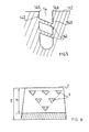
- FIG. 8 shows a schematic section of a tread 26 in new condition comprising a plurality of incisions 27 provided with a plurality of connecting elements 28 .
- the running surface is provided with a plurality of cutouts 29 of shallow depth intended to play an active role in the first times of use of the tread. After partial wear of the strip, the incisions 29 disappear to make way for the underlying incisions 27.
- An alternative embodiment of the spacers consists of using a material in the form of a fabric comprising warp threads and weft threads, said fabric having the property of resisting the vulcanization of said strip and of being able gradually eliminate during rolling of the tire, the spaces delimited by the weft threads and the warp threads allowing the molding of the connecting elements of said cutout.
- the material constituting the spacers can also be formed of one or several wires forming a network of wires which can be eliminated entirely after vulcanization of the tread or gradually during rolling.
- the manufacturing method according to the invention also allows cuts to be made, the walls of which are covered with a mixture of rubber different from the mixture constituting the rest of the tread, as shown in FIG. 11 , in the particular case of an incision provided with connecting elements; of course, the method which is described for forming this type of incision is also applicable to an incision not provided with connecting elements.
- a variant of this process initially consists of forming a stack composed of a non-perforated interlayer and covered on both sides with two layers of raw gum and secondly to pierce said stack according to its thickness before inserting said stack into a strip of raw gum and finally proceed with molding and vulcanization of said strip.
- the gum component the tread occupies each hole and forms each element connecting the cut thus molded.
- the interlayer 39 After vulcanization, one can eliminate, at least on the surface, the material constituting the interlayer 39 as that is visible on the figure 11-B.
- the interlayer is coated with rubber compounds which may be of the same nature as the constituent mixture of the tread, or else of a different nature. A mixture of different types gives the cutting edges better resistance to abrasion resulting from contact with the road. It can also be envisaged to use two layers of rubber compound of different nature on either side of the interlayer to take account, in particular, of a preferential direction of rolling of the tire. In addition, the layers may have different thicknesses and greater than the thickness of the interlayer. Each layer of rubber covering the interlayer may be formed from one or more layers of mixture.
- At least one cutout provided with at least one element connecting element has at least one connecting element formed from a mixture of natural rubber and different mechanical characteristics of the mixture making up the tread.
- a tire can have at the same time a plurality of certain incisions of them being provided with connecting elements and the others not, said incisions being formed for example according to one of the processes which have just been described.
- the field of application of the present invention relates to all types of tires and in particular road type tires, whether intended for equip vehicles such as passenger cars, vans, heavy goods vehicles and including metro tires. More specifically, tires intended to equip the driving axles of heavy goods vehicles have their characteristics significantly improved grip and noise when provided with a band bearing according to the invention.
- the application of a sculpture according to the invention to tires for civil engineering vehicles and more particularly of standard vehicles "dumper" is beneficial since it makes it possible to produce a tread with a plurality of cutouts while ensuring sufficient rigidity for said strip under the crushing forces and motor or braking forces.
- the best performance is obtained when at least 80% of the incisions provided with connecting elements according to the invention each have a width at least equal to 0.1 mm and at least more equal to 2 mm.
- a tread according to the invention can also be placed on a tire blank before being vulcanized with said tire blank in a suitable vulcanization mold.
- a strip according to the invention can comprise a plurality of blocks of rubber delimited by grooves, said blocks comprising at least one incision itself provided with at least one connecting element between the main walls of said incision; the grooves can also be provided with connecting elements so as to make a very efficient sculpture.
Landscapes
- Engineering & Computer Science (AREA)
- Mechanical Engineering (AREA)
- Tires In General (AREA)
- Tyre Moulding (AREA)
- Heating, Cooling, Or Curing Plastics Or The Like In General (AREA)
- Moulds For Moulding Plastics Or The Like (AREA)
- Steps, Ramps, And Handrails (AREA)
Applications Claiming Priority (3)
| Application Number | Priority Date | Filing Date | Title |
|---|---|---|---|
| FR9701846 | 1997-02-12 | ||
| FR9701846A FR2759323B1 (fr) | 1997-02-12 | 1997-02-12 | Sculpture de bande de roulement et procede de fabrication |
| PCT/EP1998/000625 WO1998035842A1 (fr) | 1997-02-12 | 1998-02-05 | Sculpture de bande de roulement et procede de fabrication |
Publications (2)
| Publication Number | Publication Date |
|---|---|
| EP1007378A1 EP1007378A1 (fr) | 2000-06-14 |
| EP1007378B1 true EP1007378B1 (fr) | 2002-10-02 |
Family
ID=9503821
Family Applications (1)
| Application Number | Title | Priority Date | Filing Date |
|---|---|---|---|
| EP98906920A Expired - Lifetime EP1007378B1 (fr) | 1997-02-12 | 1998-02-05 | Sculpture de bande de roulement et procede de fabrication |
Country Status (17)
| Country | Link |
|---|---|
| US (1) | US6484772B1 (enExample) |
| EP (1) | EP1007378B1 (enExample) |
| JP (1) | JP4339408B2 (enExample) |
| KR (1) | KR100578266B1 (enExample) |
| CN (1) | CN1099970C (enExample) |
| AT (1) | ATE225263T1 (enExample) |
| AU (1) | AU735104B2 (enExample) |
| BR (1) | BR9807204A (enExample) |
| CA (1) | CA2279825C (enExample) |
| DE (1) | DE69808492T2 (enExample) |
| DK (1) | DK1007378T3 (enExample) |
| ES (1) | ES2185148T3 (enExample) |
| FR (1) | FR2759323B1 (enExample) |
| NO (1) | NO316215B1 (enExample) |
| PL (1) | PL188025B1 (enExample) |
| RU (1) | RU2209140C2 (enExample) |
| WO (1) | WO1998035842A1 (enExample) |
Families Citing this family (46)
| Publication number | Priority date | Publication date | Assignee | Title |
|---|---|---|---|---|
| FR2772663A1 (fr) * | 1997-12-24 | 1999-06-25 | Michelin & Cie | Procede et element moulant pour mouler une decoupure dans une bande de roulement de pneumatique |
| ATE249344T1 (de) | 1998-07-03 | 2003-09-15 | Michelin Rech Tech | Reifenlauffläche mit einschnitten ,welche gummiblöcke begrenzen |
| FR2790717A1 (fr) | 1999-03-10 | 2000-09-15 | Michelin Soc Tech | Sculpture de bande de roulement et moule |
| FR2793188A1 (fr) | 1999-05-06 | 2000-11-10 | Michelin Soc Tech | Element moulant et moule pour le moulage d'une decoupure dans une bande de roulement |
| ATE231445T1 (de) * | 1999-06-28 | 2003-02-15 | Michelin Soc Tech | Laufflächenprofil geeignet zum begrenzen des durch das laufen des reifens erzeugten geräusches |
| FR2801531A1 (fr) * | 1999-11-25 | 2001-06-01 | Michelin Soc Tech | Moule de bande de roulement |
| FR2805215B1 (fr) | 2000-02-17 | 2002-10-25 | Michelin Soc Tech | Sculpture de bande de roulement de pneumatique et moule |
| ATE354483T1 (de) | 2001-01-29 | 2007-03-15 | Michelin Soc Tech | Rollgeräusch reduzierende lauffläche |
| US6631746B2 (en) * | 2001-04-25 | 2003-10-14 | Bridgestone/Firestone North American Tire, Llc | Undercut tie bar for pneumatic tire |
| ATE390270T1 (de) * | 2001-05-03 | 2008-04-15 | Michelin Soc Tech | Nachschneidbare lauffläche und verfahren zu deren erhalt |
| JP3996390B2 (ja) * | 2001-12-26 | 2007-10-24 | 住友ゴム工業株式会社 | タイヤの成形金型、及びそれによって製造された空気入りタイヤ |
| DE602004009186T2 (de) | 2003-06-16 | 2008-06-26 | Société de Technologie Michelin | Laufflächeprofil das mindestens ein eingesetztes element hat |
| JP2006168501A (ja) * | 2004-12-15 | 2006-06-29 | Bridgestone Corp | 空気入りタイヤ |
| FR2879956B1 (fr) * | 2004-12-24 | 2007-03-02 | Michelin Soc Tech | Methode de fabrication d'une bande de roulement pour pneumatique |
| US7276198B2 (en) * | 2004-12-28 | 2007-10-02 | The Goodyear Tire & Rubber Company | Method and mold for making tire with tie bar |
| US7468153B2 (en) * | 2004-12-30 | 2008-12-23 | The Goodyear Tire & Rubber Co. | Degradable blading for tire curing molds |
| FR2888163B1 (fr) | 2005-07-05 | 2007-09-14 | Michelin Soc Tech | Bande de roulement comportant une sculpture avec des incisions. |
| FR2898298B1 (fr) * | 2006-03-08 | 2010-08-20 | Michelin Soc Tech | Incision de bande de roulement comprenant des parties de blocage. |
| JP4316603B2 (ja) * | 2006-11-27 | 2009-08-19 | 東洋ゴム工業株式会社 | 空気入りタイヤ |
| JP4711314B2 (ja) * | 2007-09-28 | 2011-06-29 | 東洋ゴム工業株式会社 | 空気入りタイヤ |
| JP4812039B2 (ja) * | 2007-10-01 | 2011-11-09 | 東洋ゴム工業株式会社 | 空気入りタイヤ |
| JP4759004B2 (ja) | 2008-02-01 | 2011-08-31 | 東洋ゴム工業株式会社 | 空気入りタイヤ |
| FR2942991A1 (fr) * | 2009-03-11 | 2010-09-17 | Michelin Soc Tech | Procede et dispositif de realisation d'entailles dans une bande de roulement non vulcanisee |
| CN103384593B (zh) * | 2011-02-22 | 2015-09-09 | 株式会社普利司通 | 轮胎制造方法和预硫化胎面 |
| US9616716B2 (en) | 2011-12-14 | 2017-04-11 | Bridgestone Americas Tire Operations, Llc | Three dimensional sipe |
| EP2817162B1 (en) * | 2012-01-31 | 2018-08-15 | Compagnie Générale des Etablissements Michelin | Projecting features molded within submerged tread voids |
| FR2990644B1 (fr) * | 2012-05-18 | 2014-05-09 | Michelin & Cie | Dispositif anti bruit ameliore pour pneu. |
| CN104487225B (zh) | 2012-06-28 | 2018-04-27 | 汉高股份有限及两合公司 | 复合插入件的制造方法 |
| GB201315391D0 (en) * | 2013-08-29 | 2013-10-16 | Agco Int Gmbh | Tyre pressure control system |
| US20180001715A1 (en) * | 2014-12-26 | 2018-01-04 | Compagnie Generale Des Etablissements Michelin | Tire tread for reducing noise |
| JP2018524228A (ja) | 2015-06-29 | 2018-08-30 | コンパニー ゼネラール デ エタブリッスマン ミシュラン | 騒音を低減するタイヤトレッド |
| CN108136620B (zh) * | 2015-09-30 | 2020-06-16 | 米其林企业总公司 | 用于制造噪音降低胎面的模制元件及模具 |
| US10800119B2 (en) * | 2015-09-30 | 2020-10-13 | Compagnie Generale Des Etablissements Michelin | Method for manufacturing a noise reducing tread |
| WO2017056458A1 (en) | 2015-09-30 | 2017-04-06 | Compagnie Generale Des Etablissements Michelin | Molding element for manufacturing a noise reducing tread |
| US10427370B2 (en) * | 2015-09-30 | 2019-10-01 | Compagnie Generale Des Etablissements Michelin | Molding element for manufacturing a noise reducing tread |
| CN108136621B (zh) * | 2015-09-30 | 2020-04-07 | 米其林企业总公司 | 用于制造噪音降低胎面的模制元件 |
| WO2017110663A1 (en) * | 2015-12-25 | 2017-06-29 | Compagnie Generale Des Etablissements Michelin | A noise reducing tread |
| WO2018044305A1 (en) | 2016-08-31 | 2018-03-08 | Compagnie Generale Des Etablissements Michelin | Tire tread |
| FR3058091A1 (fr) * | 2016-11-03 | 2018-05-04 | Compagnie Generale Des Etablissements Michelin | Bande de roulement comportant un bloc allonge presentant une pluralite de decoupures |
| DE102018209742A1 (de) * | 2018-06-18 | 2019-12-19 | Continental Reifen Deutschland Gmbh | Fahrzeugluftreifen |
| FR3090484A3 (fr) * | 2018-12-21 | 2020-06-26 | Michelin & Cie | Bande de roulement de pneu pour poids lourd ayant des incisions améliorées. |
| EP4054865B1 (en) * | 2019-11-04 | 2025-09-03 | Atturo Tire Corp. | A system and method for altering tire noise |
| USD1095384S1 (en) | 2024-03-15 | 2025-09-30 | Atturo Tire Corp. | Wheel |
| USD1091423S1 (en) | 2024-03-15 | 2025-09-02 | Atturo Tire Corp. | Wheel |
| USD1091422S1 (en) | 2024-03-15 | 2025-09-02 | Atturo Tire Corp. | Wheel |
| USD1098998S1 (en) | 2024-03-15 | 2025-10-21 | Atturo Tire Corp. | Wheel |
Family Cites Families (21)
| Publication number | Priority date | Publication date | Assignee | Title |
|---|---|---|---|---|
| US1301343A (en) * | 1917-07-23 | 1919-04-22 | Herbert R Waterman | Non-skid tire. |
| US2201668A (en) * | 1937-07-19 | 1940-05-21 | Gen Tire & Rubber Co | Method of making vehicle tire treads |
| GB515129A (en) * | 1938-06-11 | 1939-11-27 | Dunlop Rubber Co | Improvements in tyre treads and other non-slip surfaces, and in their production |
| US2345518A (en) * | 1941-01-24 | 1944-03-28 | Webster Rubber Company | Tire tread and method of making the same |
| US2476786A (en) * | 1943-10-01 | 1949-07-19 | Wallis Leonard Francis | Formation of rubber treads on vehicle tires |
| US2708957A (en) * | 1950-01-04 | 1955-05-24 | Us Rubber Co | Anti-skid tire tread |
| US2661041A (en) * | 1950-03-23 | 1953-12-01 | Armstrong Rubber Co | Tread construction for tire casings |
| GB2061837A (en) * | 1979-10-31 | 1981-05-20 | Dunlop Ltd | Tyre treads |
| JPS63137003A (ja) * | 1986-11-29 | 1988-06-09 | Yokohama Rubber Co Ltd:The | 雪氷路用タイヤ |
| JPH0257407A (ja) * | 1988-05-19 | 1990-02-27 | Sumitomo Rubber Ind Ltd | 空気入りタイヤ |
| JP2819510B2 (ja) * | 1988-11-04 | 1998-10-30 | 住友ゴム工業 株式会社 | 自動車用タイヤ |
| JPH02310108A (ja) * | 1989-05-24 | 1990-12-25 | Toyo Tire & Rubber Co Ltd | 空気入りタイヤのトレッド外皮 |
| SU1664598A1 (ru) * | 1989-05-29 | 1991-07-23 | Научно-исследовательский институт шинной промышленности | Протектор пневматической шины |
| JPH0314704A (ja) * | 1989-06-09 | 1991-01-23 | Toyo Tire & Rubber Co Ltd | 空気入りタイヤ |
| JPH04353432A (ja) * | 1991-05-31 | 1992-12-08 | Toyo Tire & Rubber Co Ltd | 空気入りタイヤ成形用サイプブレード及び金型 |
| DE4403662C2 (de) * | 1994-02-05 | 2001-04-19 | Uniroyal Englebert Gmbh | Fahrzeugreifen |
| JPH092020A (ja) * | 1995-06-15 | 1997-01-07 | Sumitomo Rubber Ind Ltd | 空気入りタイヤ |
| EP0820885A3 (en) * | 1996-07-24 | 1998-07-08 | Bridgestone Corporation | Pneumatic tire |
| JPH10151915A (ja) * | 1996-11-21 | 1998-06-09 | Sumitomo Rubber Ind Ltd | 空気入りタイヤ |
| FR2759321B1 (fr) * | 1997-02-12 | 1999-03-19 | Michelin & Cie | Procede de fabrication et moule de bande de roulement |
| FR2772663A1 (fr) * | 1997-12-24 | 1999-06-25 | Michelin & Cie | Procede et element moulant pour mouler une decoupure dans une bande de roulement de pneumatique |
-
1997
- 1997-02-12 FR FR9701846A patent/FR2759323B1/fr not_active Expired - Fee Related
-
1998
- 1998-02-05 AT AT98906920T patent/ATE225263T1/de not_active IP Right Cessation
- 1998-02-05 BR BR9807204-8A patent/BR9807204A/pt not_active IP Right Cessation
- 1998-02-05 AU AU62950/98A patent/AU735104B2/en not_active Ceased
- 1998-02-05 PL PL33638998A patent/PL188025B1/pl not_active IP Right Cessation
- 1998-02-05 JP JP53530198A patent/JP4339408B2/ja not_active Expired - Fee Related
- 1998-02-05 CN CN98803291A patent/CN1099970C/zh not_active Expired - Fee Related
- 1998-02-05 DE DE69808492T patent/DE69808492T2/de not_active Expired - Lifetime
- 1998-02-05 WO PCT/EP1998/000625 patent/WO1998035842A1/fr not_active Ceased
- 1998-02-05 EP EP98906920A patent/EP1007378B1/fr not_active Expired - Lifetime
- 1998-02-05 ES ES98906920T patent/ES2185148T3/es not_active Expired - Lifetime
- 1998-02-05 CA CA002279825A patent/CA2279825C/fr not_active Expired - Fee Related
- 1998-02-05 DK DK98906920T patent/DK1007378T3/da active
- 1998-02-05 KR KR1019997007245A patent/KR100578266B1/ko not_active Expired - Fee Related
- 1998-02-05 RU RU99119588/28A patent/RU2209140C2/ru not_active IP Right Cessation
-
1999
- 1999-07-30 US US09/364,646 patent/US6484772B1/en not_active Expired - Lifetime
- 1999-08-02 NO NO19993743A patent/NO316215B1/no not_active IP Right Cessation
Also Published As
| Publication number | Publication date |
|---|---|
| FR2759323B1 (fr) | 1999-03-19 |
| FR2759323A1 (fr) | 1998-08-14 |
| NO316215B1 (no) | 2003-12-29 |
| CA2279825A1 (fr) | 1998-08-20 |
| EP1007378A1 (fr) | 2000-06-14 |
| DK1007378T3 (da) | 2003-02-10 |
| CA2279825C (fr) | 2006-04-18 |
| WO1998035842A1 (fr) | 1998-08-20 |
| PL188025B1 (pl) | 2004-11-30 |
| NO993743L (no) | 1999-10-08 |
| DE69808492D1 (de) | 2002-11-07 |
| PL336389A1 (en) | 2000-06-19 |
| DE69808492T2 (de) | 2003-08-07 |
| ATE225263T1 (de) | 2002-10-15 |
| KR100578266B1 (ko) | 2006-05-11 |
| AU735104B2 (en) | 2001-06-28 |
| ES2185148T3 (es) | 2003-04-16 |
| NO993743D0 (no) | 1999-08-02 |
| KR20000070979A (ko) | 2000-11-25 |
| CN1099970C (zh) | 2003-01-29 |
| CN1250413A (zh) | 2000-04-12 |
| AU6295098A (en) | 1998-09-08 |
| JP2001511733A (ja) | 2001-08-14 |
| BR9807204A (pt) | 2000-05-23 |
| JP4339408B2 (ja) | 2009-10-07 |
| RU2209140C2 (ru) | 2003-07-27 |
| US6484772B1 (en) | 2002-11-26 |
Similar Documents
| Publication | Publication Date | Title |
|---|---|---|
| EP1007378B1 (fr) | Sculpture de bande de roulement et procede de fabrication | |
| EP1506099B1 (fr) | Bande de roulement evolutive | |
| EP1358079B1 (fr) | Bande de roulement reduisant le bruit de roulage | |
| EP0858875B1 (fr) | Procédé de fabrication d'une bande de roulement pour pneus et moule utilisé dans la méthode | |
| FR2973285A1 (fr) | Bande de roulement comprenant au moins une rainure ondulante et procede d'obtention | |
| EP2533987B1 (fr) | Pneumatique pour vehicules a deux roues comportant une bande de roulement presentant des incisions | |
| WO2002038399A2 (fr) | Bande de roulement de pneumatique et element moulant de moule d'une telle bande | |
| EP3439897B1 (fr) | Bande de roulement pour pneu | |
| EP3648991B1 (fr) | Pneu dont la bande de roulement comprend des rainures ondulantes | |
| EP3094503A1 (fr) | Bande de roulement évolutive pour pneu | |
| EP2790905B1 (fr) | Element moulant comportant des moyens de decoupe pour le moulage et la vulcanisation d'une bande de roulement d'un pneumatique | |
| EP1259389B1 (fr) | Sculpture de bande de roulement de pneumatique | |
| EP3439898A1 (fr) | Bande de roulement de pneu | |
| EP1646514B1 (fr) | Sculpture de bande de roulement ayant au moins un element intercalé | |
| EP1638785B1 (fr) | Element protecteur d'une bande de roulement | |
| EP1034946B1 (fr) | Sculpture de bande de roulement et moule | |
| EP3535139A1 (fr) | Bande de roulement comportant un bloc allonge presentant une pluralite de decoupures | |
| EP1097826B1 (fr) | Motif de sculpture d'une bande de roulement | |
| FR3002489A1 (fr) | Bande de roulement amelioree pour pneu de genie civil | |
| WO2017174927A1 (fr) | Bande de roulement améliorée pour pneu | |
| CA2867582A1 (fr) | Bande de roulement de grande epaisseur pour pneu de genie civil | |
| FR3130691A1 (fr) | Pneumatique présentant un compromis de performances entre adhérence sur neige et bruit de roulement | |
| FR3127159A1 (fr) | Pneumatique avec des performances d’adhérence transversale améliorées sur sol enneigé | |
| BE892900A (fr) | Bande de roulement de pneumatique |
Legal Events
| Date | Code | Title | Description |
|---|---|---|---|
| PUAI | Public reference made under article 153(3) epc to a published international application that has entered the european phase |
Free format text: ORIGINAL CODE: 0009012 |
|
| 17P | Request for examination filed |
Effective date: 19990913 |
|
| AK | Designated contracting states |
Kind code of ref document: A1 Designated state(s): AT BE CH DE DK ES FI FR GB GR IE IT LI LU MC NL PT SE |
|
| 17Q | First examination report despatched |
Effective date: 20010511 |
|
| GRAG | Despatch of communication of intention to grant |
Free format text: ORIGINAL CODE: EPIDOS AGRA |
|
| GRAG | Despatch of communication of intention to grant |
Free format text: ORIGINAL CODE: EPIDOS AGRA |
|
| GRAH | Despatch of communication of intention to grant a patent |
Free format text: ORIGINAL CODE: EPIDOS IGRA |
|
| GRAH | Despatch of communication of intention to grant a patent |
Free format text: ORIGINAL CODE: EPIDOS IGRA |
|
| GRAA | (expected) grant |
Free format text: ORIGINAL CODE: 0009210 |
|
| AK | Designated contracting states |
Kind code of ref document: B1 Designated state(s): AT BE CH DE DK ES FI FR GB GR IE IT LI LU MC NL PT SE |
|
| PG25 | Lapsed in a contracting state [announced via postgrant information from national office to epo] |
Ref country code: IE Free format text: LAPSE BECAUSE OF FAILURE TO SUBMIT A TRANSLATION OF THE DESCRIPTION OR TO PAY THE FEE WITHIN THE PRESCRIBED TIME-LIMIT Effective date: 20021002 Ref country code: GR Free format text: LAPSE BECAUSE OF FAILURE TO SUBMIT A TRANSLATION OF THE DESCRIPTION OR TO PAY THE FEE WITHIN THE PRESCRIBED TIME-LIMIT Effective date: 20021002 |
|
| REF | Corresponds to: |
Ref document number: 225263 Country of ref document: AT Date of ref document: 20021015 Kind code of ref document: T |
|
| REG | Reference to a national code |
Ref country code: GB Ref legal event code: FG4D Free format text: NOT ENGLISH |
|
| REG | Reference to a national code |
Ref country code: CH Ref legal event code: EP |
|
| REG | Reference to a national code |
Ref country code: IE Ref legal event code: FG4D Free format text: FRENCH |
|
| REF | Corresponds to: |
Ref document number: 69808492 Country of ref document: DE Date of ref document: 20021107 |
|
| PG25 | Lapsed in a contracting state [announced via postgrant information from national office to epo] |
Ref country code: PT Free format text: LAPSE BECAUSE OF FAILURE TO SUBMIT A TRANSLATION OF THE DESCRIPTION OR TO PAY THE FEE WITHIN THE PRESCRIBED TIME-LIMIT Effective date: 20030102 |
|
| REG | Reference to a national code |
Ref country code: DK Ref legal event code: T3 |
|
| GBT | Gb: translation of ep patent filed (gb section 77(6)(a)/1977) |
Effective date: 20030122 |
|
| PG25 | Lapsed in a contracting state [announced via postgrant information from national office to epo] |
Ref country code: MC Free format text: LAPSE BECAUSE OF NON-PAYMENT OF DUE FEES Effective date: 20030228 Ref country code: LI Free format text: LAPSE BECAUSE OF NON-PAYMENT OF DUE FEES Effective date: 20030228 Ref country code: CH Free format text: LAPSE BECAUSE OF NON-PAYMENT OF DUE FEES Effective date: 20030228 |
|
| REG | Reference to a national code |
Ref country code: ES Ref legal event code: FG2A Ref document number: 2185148 Country of ref document: ES Kind code of ref document: T3 |
|
| REG | Reference to a national code |
Ref country code: IE Ref legal event code: FD4D Ref document number: 1007378E Country of ref document: IE |
|
| PLBE | No opposition filed within time limit |
Free format text: ORIGINAL CODE: 0009261 |
|
| STAA | Information on the status of an ep patent application or granted ep patent |
Free format text: STATUS: NO OPPOSITION FILED WITHIN TIME LIMIT |
|
| 26N | No opposition filed |
Effective date: 20030703 |
|
| REG | Reference to a national code |
Ref country code: CH Ref legal event code: PL |
|
| PGFP | Annual fee paid to national office [announced via postgrant information from national office to epo] |
Ref country code: ES Payment date: 20090219 Year of fee payment: 12 Ref country code: DK Payment date: 20090213 Year of fee payment: 12 Ref country code: AT Payment date: 20090218 Year of fee payment: 12 |
|
| PGFP | Annual fee paid to national office [announced via postgrant information from national office to epo] |
Ref country code: NL Payment date: 20090217 Year of fee payment: 12 Ref country code: FI Payment date: 20090217 Year of fee payment: 12 |
|
| PGFP | Annual fee paid to national office [announced via postgrant information from national office to epo] |
Ref country code: GB Payment date: 20090219 Year of fee payment: 12 |
|
| PGFP | Annual fee paid to national office [announced via postgrant information from national office to epo] |
Ref country code: BE Payment date: 20090408 Year of fee payment: 12 |
|
| BERE | Be: lapsed |
Owner name: CIE GENERALE DES ETS *MICHELIN-MICHELIN & CIE Effective date: 20100228 |
|
| REG | Reference to a national code |
Ref country code: NL Ref legal event code: V1 Effective date: 20100901 |
|
| REG | Reference to a national code |
Ref country code: DK Ref legal event code: EBP |
|
| GBPC | Gb: european patent ceased through non-payment of renewal fee |
Effective date: 20100205 |
|
| PG25 | Lapsed in a contracting state [announced via postgrant information from national office to epo] |
Ref country code: FI Free format text: LAPSE BECAUSE OF NON-PAYMENT OF DUE FEES Effective date: 20100205 Ref country code: AT Free format text: LAPSE BECAUSE OF NON-PAYMENT OF DUE FEES Effective date: 20100205 |
|
| PG25 | Lapsed in a contracting state [announced via postgrant information from national office to epo] |
Ref country code: NL Free format text: LAPSE BECAUSE OF NON-PAYMENT OF DUE FEES Effective date: 20100901 Ref country code: DK Free format text: LAPSE BECAUSE OF NON-PAYMENT OF DUE FEES Effective date: 20100228 |
|
| PG25 | Lapsed in a contracting state [announced via postgrant information from national office to epo] |
Ref country code: BE Free format text: LAPSE BECAUSE OF NON-PAYMENT OF DUE FEES Effective date: 20100228 |
|
| REG | Reference to a national code |
Ref country code: ES Ref legal event code: FD2A Effective date: 20110308 |
|
| PG25 | Lapsed in a contracting state [announced via postgrant information from national office to epo] |
Ref country code: GB Free format text: LAPSE BECAUSE OF NON-PAYMENT OF DUE FEES Effective date: 20100205 |
|
| PGFP | Annual fee paid to national office [announced via postgrant information from national office to epo] |
Ref country code: SE Payment date: 20110214 Year of fee payment: 14 Ref country code: DE Payment date: 20110218 Year of fee payment: 14 Ref country code: LU Payment date: 20110225 Year of fee payment: 14 Ref country code: IT Payment date: 20110221 Year of fee payment: 14 |
|
| PG25 | Lapsed in a contracting state [announced via postgrant information from national office to epo] |
Ref country code: ES Free format text: LAPSE BECAUSE OF NON-PAYMENT OF DUE FEES Effective date: 20110307 |
|
| PG25 | Lapsed in a contracting state [announced via postgrant information from national office to epo] |
Ref country code: ES Free format text: LAPSE BECAUSE OF NON-PAYMENT OF DUE FEES Effective date: 20100206 |
|
| PG25 | Lapsed in a contracting state [announced via postgrant information from national office to epo] |
Ref country code: SE Free format text: LAPSE BECAUSE OF NON-PAYMENT OF DUE FEES Effective date: 20120206 |
|
| PG25 | Lapsed in a contracting state [announced via postgrant information from national office to epo] |
Ref country code: IT Free format text: LAPSE BECAUSE OF NON-PAYMENT OF DUE FEES Effective date: 20120205 |
|
| REG | Reference to a national code |
Ref country code: DE Ref legal event code: R119 Ref document number: 69808492 Country of ref document: DE Effective date: 20120901 |
|
| PG25 | Lapsed in a contracting state [announced via postgrant information from national office to epo] |
Ref country code: DE Free format text: LAPSE BECAUSE OF NON-PAYMENT OF DUE FEES Effective date: 20120901 |
|
| PG25 | Lapsed in a contracting state [announced via postgrant information from national office to epo] |
Ref country code: LU Free format text: LAPSE BECAUSE OF NON-PAYMENT OF DUE FEES Effective date: 20120205 |
|
| REG | Reference to a national code |
Ref country code: FR Ref legal event code: PLFP Year of fee payment: 19 |
|
| REG | Reference to a national code |
Ref country code: FR Ref legal event code: PLFP Year of fee payment: 20 |
|
| PGFP | Annual fee paid to national office [announced via postgrant information from national office to epo] |
Ref country code: FR Payment date: 20170217 Year of fee payment: 20 |