EP1007378B1 - Tread pattern and method for making same - Google Patents
Tread pattern and method for making same Download PDFInfo
- Publication number
- EP1007378B1 EP1007378B1 EP98906920A EP98906920A EP1007378B1 EP 1007378 B1 EP1007378 B1 EP 1007378B1 EP 98906920 A EP98906920 A EP 98906920A EP 98906920 A EP98906920 A EP 98906920A EP 1007378 B1 EP1007378 B1 EP 1007378B1
- Authority
- EP
- European Patent Office
- Prior art keywords
- tread
- cutouts
- cutout
- walls
- tyre
- Prior art date
- Legal status (The legal status is an assumption and is not a legal conclusion. Google has not performed a legal analysis and makes no representation as to the accuracy of the status listed.)
- Expired - Lifetime
Links
- 238000000034 method Methods 0.000 title claims description 23
- 229920001971 elastomer Polymers 0.000 claims abstract description 61
- 238000004519 manufacturing process Methods 0.000 claims abstract description 22
- 239000000463 material Substances 0.000 claims description 29
- 238000004073 vulcanization Methods 0.000 claims description 26
- 238000000465 moulding Methods 0.000 claims description 15
- 230000007423 decrease Effects 0.000 claims description 8
- 238000003780 insertion Methods 0.000 claims description 5
- 230000037431 insertion Effects 0.000 claims description 5
- 239000012530 fluid Substances 0.000 claims description 4
- 238000002844 melting Methods 0.000 claims description 4
- 230000008018 melting Effects 0.000 claims description 4
- 238000005299 abrasion Methods 0.000 claims description 3
- 239000004744 fabric Substances 0.000 claims description 3
- 238000007664 blowing Methods 0.000 claims description 2
- 238000009826 distribution Methods 0.000 claims description 2
- 238000000227 grinding Methods 0.000 claims description 2
- 229920001131 Pulp (paper) Polymers 0.000 claims 2
- 239000002759 woven fabric Substances 0.000 claims 1
- 238000005096 rolling process Methods 0.000 abstract description 48
- 241000913081 Scoliopteryx libatrix Species 0.000 description 24
- 239000011229 interlayer Substances 0.000 description 13
- 239000000203 mixture Substances 0.000 description 12
- 125000006850 spacer group Chemical group 0.000 description 12
- 239000010410 layer Substances 0.000 description 11
- 238000012360 testing method Methods 0.000 description 11
- 230000008569 process Effects 0.000 description 10
- XLYOFNOQVPJJNP-UHFFFAOYSA-N water Substances O XLYOFNOQVPJJNP-UHFFFAOYSA-N 0.000 description 9
- 230000000694 effects Effects 0.000 description 7
- 150000001875 compounds Chemical class 0.000 description 4
- 230000006872 improvement Effects 0.000 description 4
- 230000008901 benefit Effects 0.000 description 3
- 238000005520 cutting process Methods 0.000 description 3
- 230000009467 reduction Effects 0.000 description 3
- 230000009471 action Effects 0.000 description 2
- 239000000956 alloy Substances 0.000 description 2
- 229910045601 alloy Inorganic materials 0.000 description 2
- 244000043261 Hevea brasiliensis Species 0.000 description 1
- 230000002159 abnormal effect Effects 0.000 description 1
- 230000004075 alteration Effects 0.000 description 1
- 238000013459 approach Methods 0.000 description 1
- 238000005452 bending Methods 0.000 description 1
- 230000009286 beneficial effect Effects 0.000 description 1
- 239000011248 coating agent Substances 0.000 description 1
- 238000000576 coating method Methods 0.000 description 1
- 230000000295 complement effect Effects 0.000 description 1
- 239000000470 constituent Substances 0.000 description 1
- 125000004122 cyclic group Chemical group 0.000 description 1
- 230000000593 degrading effect Effects 0.000 description 1
- 230000002349 favourable effect Effects 0.000 description 1
- 238000007373 indentation Methods 0.000 description 1
- 238000009434 installation Methods 0.000 description 1
- 230000001788 irregular Effects 0.000 description 1
- 238000003698 laser cutting Methods 0.000 description 1
- 230000002045 lasting effect Effects 0.000 description 1
- 230000004807 localization Effects 0.000 description 1
- 230000014759 maintenance of location Effects 0.000 description 1
- 238000005259 measurement Methods 0.000 description 1
- 239000002184 metal Substances 0.000 description 1
- 229920003052 natural elastomer Polymers 0.000 description 1
- 229920001194 natural rubber Polymers 0.000 description 1
- 230000010355 oscillation Effects 0.000 description 1
- 238000004080 punching Methods 0.000 description 1
- 238000007493 shaping process Methods 0.000 description 1
- 238000004088 simulation Methods 0.000 description 1
- 239000004575 stone Substances 0.000 description 1
Images


Classifications
-
- B—PERFORMING OPERATIONS; TRANSPORTING
- B60—VEHICLES IN GENERAL
- B60C—VEHICLE TYRES; TYRE INFLATION; TYRE CHANGING; CONNECTING VALVES TO INFLATABLE ELASTIC BODIES IN GENERAL; DEVICES OR ARRANGEMENTS RELATED TO TYRES
- B60C11/00—Tyre tread bands; Tread patterns; Anti-skid inserts
- B60C11/03—Tread patterns
- B60C11/04—Tread patterns in which the raised area of the pattern consists only of continuous circumferential ribs, e.g. zig-zag
-
- B—PERFORMING OPERATIONS; TRANSPORTING
- B60—VEHICLES IN GENERAL
- B60C—VEHICLE TYRES; TYRE INFLATION; TYRE CHANGING; CONNECTING VALVES TO INFLATABLE ELASTIC BODIES IN GENERAL; DEVICES OR ARRANGEMENTS RELATED TO TYRES
- B60C11/00—Tyre tread bands; Tread patterns; Anti-skid inserts
- B60C11/03—Tread patterns
- B60C11/13—Tread patterns characterised by the groove cross-section, e.g. for buttressing or preventing stone-trapping
- B60C11/1369—Tie bars for linking block elements and bridging the groove
-
- B—PERFORMING OPERATIONS; TRANSPORTING
- B29—WORKING OF PLASTICS; WORKING OF SUBSTANCES IN A PLASTIC STATE IN GENERAL
- B29D—PRODUCING PARTICULAR ARTICLES FROM PLASTICS OR FROM SUBSTANCES IN A PLASTIC STATE
- B29D30/00—Producing pneumatic or solid tyres or parts thereof
- B29D30/06—Pneumatic tyres or parts thereof (e.g. produced by casting, moulding, compression moulding, injection moulding, centrifugal casting)
- B29D30/52—Unvulcanised treads, e.g. on used tyres; Retreading
-
- B—PERFORMING OPERATIONS; TRANSPORTING
- B60—VEHICLES IN GENERAL
- B60C—VEHICLE TYRES; TYRE INFLATION; TYRE CHANGING; CONNECTING VALVES TO INFLATABLE ELASTIC BODIES IN GENERAL; DEVICES OR ARRANGEMENTS RELATED TO TYRES
- B60C11/00—Tyre tread bands; Tread patterns; Anti-skid inserts
- B60C11/03—Tread patterns
- B60C11/12—Tread patterns characterised by the use of narrow slits or incisions, e.g. sipes
- B60C11/1259—Depth of the sipe
- B60C11/1263—Depth of the sipe different within the same sipe
-
- B—PERFORMING OPERATIONS; TRANSPORTING
- B60—VEHICLES IN GENERAL
- B60C—VEHICLE TYRES; TYRE INFLATION; TYRE CHANGING; CONNECTING VALVES TO INFLATABLE ELASTIC BODIES IN GENERAL; DEVICES OR ARRANGEMENTS RELATED TO TYRES
- B60C11/00—Tyre tread bands; Tread patterns; Anti-skid inserts
- B60C11/03—Tread patterns
- B60C11/13—Tread patterns characterised by the groove cross-section, e.g. for buttressing or preventing stone-trapping
-
- Y—GENERAL TAGGING OF NEW TECHNOLOGICAL DEVELOPMENTS; GENERAL TAGGING OF CROSS-SECTIONAL TECHNOLOGIES SPANNING OVER SEVERAL SECTIONS OF THE IPC; TECHNICAL SUBJECTS COVERED BY FORMER USPC CROSS-REFERENCE ART COLLECTIONS [XRACs] AND DIGESTS
- Y10—TECHNICAL SUBJECTS COVERED BY FORMER USPC
- Y10S—TECHNICAL SUBJECTS COVERED BY FORMER USPC CROSS-REFERENCE ART COLLECTIONS [XRACs] AND DIGESTS
- Y10S152/00—Resilient tires and wheels
- Y10S152/03—Slits in threads
Definitions
- the invention relates to treads intended for the manufacture of new tires or retreading tires, and in particular treads for said strips comprising a large number of cutouts occurring under the form of grooves and / or incisions. It also relates to a manufacturing process allowing such bands to be produced.
- adhesion we mean both grip characteristics of the tire in the transverse direction to the movement of the vehicle (cornering) than that of the tire in the direction longitudinal to the movement of the vehicle (possibility of transmitting a force to the ground brake or motor).
- this strip In order to increase the grip potential of a tread of a tire rolling on a road coated with water, it is known to provide this strip of a sculpture formed by a plurality of cutouts made more or less deep into said strip, said cutouts opening onto the surface of said strip strip in contact with the road (this surface is called the rolling surface).
- Certain cuts can lead to at least one other cut.
- the trace of a cut on the tread surface of a tread follows a profile geometric mean determined as the geometric profile located at a distance average of the edges formed by the walls of said cutout on the surface of rolling.
- the middle axis of the trace of a cut on the running surface corresponds to the line of least squares of the distances of the points of the mean profile of the trace of said cut.
- tread stiffness means the stiffness of the tread under the actions combined compressive and shear forces in the region affected by contact with the road. Jointly, the presence of numerous cutouts forming water drainage channels induces a noise level when driving on dry roads which is now considered a nuisance that we want to reduce as much as possible particularly on newly designed vehicles. This rolling noise is amplified by the cyclic movements of closing and opening of the cutouts associated with the friction of the walls of said cutouts when they are closed.
- patent FR 1 028 978 a solution is proposed to this problem consisting in providing the tread with a plurality of circumferential incisions of shallow depth on the tread surface of the new band so as to increase the flexibility of said strip only in the vicinity of the running surface.
- the tire being intended, once mounted on a vehicle, to ensure good performance throughout the life of said tire (i.e. until the wear of its tread corresponding at least to the legal level allowed) it it is necessary to provide a tread whose tread ensures the durability of grip performance on wet surfaces.
- EP-A-0 342 908 which is a document of the state of the art relevant prior, describes a tread whose characteristics correspond to those of the preamble of claim 1.
- the object of the present invention is to develop a tread for tire which combines both a very good level of grip on wet roads and on dry roads with low noise emission when driving in new condition and during minus a large part of the life of said strip.
- one of the objectives of the invention is to control the evolution of performance with wear of the tread.
- a tread of thickness E made of a rubber mixture, intended to be placed radially outside a tire, said strip being provided with a tread surface intended to come into contact. with the road while the tire is running.
- the tread is provided with a large number of cutouts so that a plurality of cutouts are affected by the area of contact of the tire with the road.
- Each cutout is defined by the space delimited mainly between two facing walls l 'from one another, said walls being perpendicular to or oblique with respect to the running surface, and each cut has a depth at most equal to the thickness E of the tread, the depth of said cut being measured as the distance, in a radial direction, of the points of the contour of said cutout furthest from the running surface of the new tire with respect to said surface.
- two main walls of at least one cutout located in the part of the tread affected by the crushing of the tire on the ground while running are connected by at least one rubber connecting element.
- S E the total connection surface on each of the walls of said cut-out equal either to the total intersection surface of the connection element in the case of a single element or to the sum of the intersection surfaces of all the connecting elements in the case of several elements and S T the total area of each of the main walls of said cutout.
- the geometric contour L of minimum length and enveloping the total connection surface S E on this wall corresponds to the contour which can be traced on said wall so as to envelop the whole of the total connection surface formed by the intersection surfaces of all the elements for connection with said wall.
- a cutout being defined as the continuous space delimited by at least two main walls facing each other, the presence of at least one connecting element between said walls, according to the invention, does not break the continuity of this space and this regardless of the level of wear of the tread comprising such a cutout.
- the effect on the adhesion and noise performance is all the more more significant than a greater number of cutouts forming the sculpture of a band tire bearings are provided with at least one connecting element rubber so as to obtain both a remarkable performance in adhesion without however degrading the level of performance in road noise.
- each surface S G delimited by the geometric contour L of minimum length and enveloping the total bonding surface S E on a main wall of a cutout is at least equal to 15% of the surface of the corresponding wall S T.
- the total connecting surface S E on at least one main wall of at least one cutout is at most equal to 80% of the surface of the corresponding wall S T , so as to maintain a cutout volume giving the strip of sufficient grip characteristics.
- a sculpture according to the invention can combine both a plurality cutouts provided with at least one connecting element with a plurality of cutouts without a connecting element, the proportion between said cutouts may for example be a function of the type of tire comprising said tread.
- the Applicant has surprisingly obtained very good rolling results with tires provided with a tread of thickness E, provided with a plurality of cutouts oriented almost in the same direction, each of said cutouts being defined by the space defined mainly between two walls facing each other, said walls being perpendicular to or oblique with respect to the rolling surface, and said cutouts having a depth h .
- depth h of a cut is meant the maximum radial distance measured between the edge of the cut closest to the running surface of the tread in new condition and the point (s) of the walls. of the cutout the farthest radially from said rolling surface. This depth h represents the maximum radial distance existing between the points radially furthest from the walls of a cutout and is at most equal to the thickness E of the tread.
- connection rate T P is less than about 0.10, the objective cannot be achieved because the connection elements do not provide enough rigidity and cannot sufficiently block the movements of the walls of the cut-out to which they are linked; preferentially, the rate of binding T P is greater than 0.25.
- active edge length of a tread of a pneumatic we mean the sum of the lengths of all the rubber edges in contact with the road in the footprint and for a level of tread wear given.
- the value of the bond rate T P S P / S T , evaluated for different wear levels of the tread decreases in a substantially regular manner with the wear of the tire, at least from a predetermined partial level of wear, S P representing, on one of the walls of said cutout, the connecting surface remaining after partial wear of the tread and S T representing the total remaining surface of said wall corresponding to the same partial level of wear of the tread.
- the effect of the connecting elements on the rigidity is maximum when the tread is new but gradually decreases with the increase in the rigidity of said strip resulting from wear.
- the draining power of the sculpture according to the invention is to say its capacity to evacuate the water present on the road, is sufficient and that whatever the level of tread wear, which is a particularly advantageous interesting for the user.
- the active edge length of the sculpture in the imprint corresponding to each level of wear is preferably defined as being at least equal to 50% of the active edge length on the running surface of the tread in new condition.
- the tread retains sufficient shear and bending rigidity when it is subjected to contact forces and this despite the presence of a very large number of cutouts, it is advisable to arrange the element (s) (S) connecting each of said cutouts so that the distance between the edge closest to the rolling surface in new condition and the points of the contour of the intersection surface of said element on said wall is at most equal to 60% of the height h of the cutout and preferably between 40% and 60% .
- Another significant improvement in the tread pattern according to the invention consists in making a plurality of cutouts provided with a number important connecting elements distributed fairly evenly in each of the cuts so as to ensure good regularity of the effect induced on the rigidity of the rubber elements delimited by the walls of the cutout.
- This tread gives the tire performance particularly homogeneous and regular whatever the degree of wear of said strip.
- Another object of the invention is to propose a method of manufacturing a strip bearing provided with a plurality of cutouts, said cutouts being provided at least one connecting element. It is clear that the usual methods of molding of the cutouts are not suitable for making such sculptures so easy and with sufficient precision. Indeed, having at least one element of connection under the running surface of the tread leads to an impossibility for demolding said strip when a conventional molding process is used and using metal blades to mold incisions.
- this tread can be produced in the form of a strip of predetermined length or in the form of a closed ring intended to be placed radially outside the tire blank during its manufacture or on a tire being retreaded.
- a variant of the process which has just been described may consist in carrying out steps a) to c) and to place the strip of unvulcanized and unmolded gum on a blank of pneumatic before proceeding to the molding and vulcanization of the assembly tire and strip thus assembled.
- this method consisting of inserting spacers in a rubber band, can also be applied in the case of the manufacture of a rubber band bearing comprising a plurality of tabs without hole for molding a plurality incisions with no connecting elements.
- the material composing the spacers and filling the cutouts provided with at least one connecting element is chosen so that it can be eliminated at least partially, i.e. at least close to the rolling surface in new condition, and gradually during taxiing to permanently maintain a long length edges.
- pulp is a filling material which is particularly suitable for this use, because this material is characterized by very low cohesion when it is in the presence of water for a sufficient period of time and therefore presents the advantage of being able to be eliminated progressively during the rolling of the tire or else of being able to be eliminated after being placed in the presence of water and before any rolling, and this all the more easily if the cutouts provided with at least one element of connection have a thickness of at least 0.4 mm.
- a variant of this process consists in choosing as the material composing the inserts a material whose melting point is sufficiently close to the vulcanization temperature of said strip so as to become fluid only towards the end of the duration of said vulcanization, taking into account the gradual rise in temperature of the rubber constituting said strip, so as to allow removal of said filling material, for example by suction or by blowing after vulcanization of said strip.
- the filling material is a alloy with a low melting point offering the advantage of being rigid during the shaping of the strip and during the vulcanization phase before becoming fluid at the end of the vulcanization of the strip so as to allow the removal of said alloy and possibly recycle it for similar use.
- the process which has just been described can also be followed by a grinding operation. almost exclusively affecting the surface of the new tread intended to make very clearly appear a plurality of edges on the rolling surface of said bandaged.
- Another way to get a good surface finish right out of the mold can consist in placing all of the cutouts provided with at least one bond under the tread surface and to mold said tread in a mold comprising a plurality of relief elements intended to mold a plurality of cutouts on the running surface and whose depth is slightly greater than the smallest of the distances separating the cutouts provided with at least one connecting element of the running surface. In this way, the tread in wearing out will gradually reveal a plurality of indentations below the surface of rolling of said new strip.
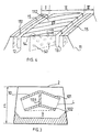
- the tread 1 partially shown in the direction of its length in FIG. 1 has a thickness E and a width W.
- One of the external walls of said strip is intended to constitute the tread surface 2 of a tire provided with said strip ; this tire can either be a new tire or a refurbished tire, that is to say a tire which has rolled until its tread has worn out, then requiring the installation of a new tread.
- a plurality of cutouts 3, 4 are made in the strip 1 so as to extend over the entire width W of said strip 1 .
- the cutout 3 is delimited by two main flat walls 5, 6 perpendicular to the rolling surface 2 and distant from each other by an average distance e equal to the width of the cutout 3 .
- the two walls 5, 6 delimiting the cutout 3 are connected to the radially innermost points 8 of the cutout relative to the rolling surface 2 .
- the intersection of the walls 5, 6 with the rolling surface 2 determines rubber edges 51 and 61 respectively, one function of which is to cut the film of water which may exist between the strip and the road.
- the cutout 3 is provided with five rubber connecting elements 7 which connect the walls 5 and 6 of said cutout, said connecting elements making it possible to keep said walls at an almost constant distance, avoiding both opening and closing of the cutout 3 .
- Figure 2 is shown a cross section of the tread 1 of Figure 1 made along the wall 6 of the cutout 3. It can be seen there, distributed fairly uniformly on the wall 6 , the intersection surfaces 71 , 72, 73, 74, 75 of the connecting elements 7 with the wall 6, the sum of said surfaces constituting the total intersection surface S E. In the present case, all the connecting elements have their intersection surfaces 71, 72, 73, 74, 75 entirely situated under the rolling surface 2 and at a radial distance from said surface less than the depth h of the cutout. .
- connection surface S E is at most equal to 80% of the surface S G delimited by the geometric contour L (in dotted lines) of minimum length constructed on the wall 6 and enveloping all the intersection surfaces 71 , 72, 73, 74, 75 of the connecting elements 7 with the wall 6 .
- the main walls of the cutouts can be flat or curved.
- the tread comprises a plurality of cutouts provided with at least one connection element and each surface S G , delimited by the geometric contour L of minimum length and enveloping the total connection surface S E on a wall of the cutout, is at least equal to 15% of the surface of the corresponding wall S T.
- the relative position of the connecting elements of the same cutout is determined so as to maintain for said cutout a large active edge length for come into contact with the ground and this regardless of the level of wear of the strip of rolling.
- Figure 3 shows the schematic section of a rib of a tread 1 made along a wall 9 of a cutout provided with a single connecting element 10 s' extending between the main walls delimiting said cutout.
- This element 10 consists of two branches 101, 102 oriented in the direction of the width of the incision and connected together by a third branch 103 oriented in the direction of the thickness of the strip.
- the contour L drawn in dotted lines corresponds to the contour of minimum length enveloping the total connection surface of the single element and passing through the ends of the branches 101 and 102 .
- An alternative embodiment consists in extending the branch 103 connecting the branches 101 and 102 to the rolling surface 2 , thereby creating a single volume corresponding to the cutout.
- FIG. 4 partially represents a tread 11 of a tire comprising incisions oriented in the circumferential direction and incisions oriented in the transverse direction, each of said incisions being provided with connecting elements and opening onto the rolling surface 112 of said strip.
- the tread 11 is axially divided into three annular regions denoted I, II, III, the middle region II being separated from the two edge regions I and III by grooves 12 and 13 oriented circumferentially.
- the middle part II there is provided in the middle part II a plurality of small width incisions 14 oriented essentially transversely, said incisions 14 emerging on each side of part II in the grooves 12 and 13.
- edge portions I and III there is provided at least one incision 15 oriented essentially in the circumferential direction. All the transverse orientation incisions 14 and the circumferential incisions 15 are provided with a plurality of connecting elements 141 and 151 respectively connecting the main walls forming said incisions.
- oriented essentially transversely it is meant that the mean axes of the traces of the incisions on the running surface 112 form with the transverse direction of the tread an angle at most equal to 45 °.
- oriented essentially circumferentially it is meant that the mean axes of the traces of the incisions on the running surface make with the transverse direction of the tread an angle at least equal to 75 ° and at most equal to 90 ° .
- the average axis of the trace of a cut on the running surface of a tread corresponds to the average direction evaluated between the points of the edges of said cut on the running surface using a method of least squares of the distances.
- connecting elements also connecting the walls delimiting the circumferential grooves separating part II from parts I and III.
- At least one connecting element of a cutout appears on the rolling surface and decreases the lengths of the edges 145, 146 correspondingly formed by each of the main walls of said cutout. with the running surface 2 .
- each connecting element 141 between a first main wall 142 and a second main wall 143 of the cutout 14 so that said element makes, with the perpendicular to the running surface of the new tread, an angle different from 90 ° and preferably between 30 ° and 70 ° .
- connecting elements arrive at the running surface after wear in a more or less offset manner makes it possible to permanently maintain (that is to say throughout the duration of use of the tire) a large length of edges in the region of the running surface affected by contact with the road and makes it possible to achieve favorable interference both on wear (this avoids the appearance of abnormal wear, that is to say localized) and on noise of rolling.
- a comparable result is obtained by making a single continuous cut and oriented at an angle close to 90 ° with the transverse direction so that the mean axis of the trace of the cut on the rolling surface forms a helix; in fact, everything takes place in the zone of contact with the road as if the strip were provided with a plurality of cutouts almost oriented in the circumferential direction.
- the cutouts provided with at least one connecting element can be perpendicular to the running surface or at least part of these, with the direction perpendicular to the running surface of the tread in new condition , an average angle at most equal to 20 ° so as to increase the efficiency of the rubber edges in certain uses so as to be able to better transmit a motor or braking force depending on the direction of orientation chosen for the inclination of said cutout.
- FIG. 6 represents, seen in a cross section, a wall of a cutout provided with connecting elements 7 arranged in rows almost parallel to the rolling surface 2; the number of connecting elements 7 per row increasing as one approaches the running surface 2 .
- Figure 7 shows an advantageous arrangement in terms of connecting the main walls of the same cut of a tread.
- a plurality of intersection surfaces 76 of connecting elements with said wall so that the density of connecting elements is relatively high (it i.e. there are a large number of elements per wall surface).
- the surface S G delimited by the contour L of minimum length and enveloping all the surfaces of intersection of the connection elements is approximately 90% of the total surface of the wall 66 while the connection surface S E represents only 40% of the total surface.
- An optimum effect on the rigidity of the strip is achieved when the connecting elements are regularly distributed on the walls of each cut.
- FIG. 9 schematically represents two types of tread pattern tested.
- FIG. 9-A corresponds to variant A of a tread 18 comprising a plurality of incisions 21 of width 0.1 mm, oriented transversely and spaced circumferentially by an average pitch p of 15 mm; this variant further comprises three circumferential grooves 19 of width 5 mm which axially divide the tread into four parts, each of said parts being further divided in two by a circumferential incision 20 of width 2 mm. All cutouts have the same depth equal to 13.5 mm.
- FIG. 9-A corresponds to variant A of a tread 18 comprising a plurality of incisions 21 of width 0.1 mm, oriented transversely and spaced circumferentially by an average pitch p of 15 mm; this variant further comprises three circumferential grooves 19 of width 5 mm which axially divide the tread into four parts, each of said parts being further divided in two by a circumferential incision 20 of width 2 mm. All cutouts have the same depth
- variant B of a tread 22 comprising a plurality of incisions 25 of width 1 mm oriented in a direction making an average angle of 15 ° with the transverse direction of the tire and spaced apart others with an average pitch p of 10 mm;
- this variant B further comprises two grooves 23 of corrugated and essentially circumferential shape 19 of width 10 mm which axially divide the tread into three parts, each of said parts being further divided in two by a circumferential incision 24 of width 2 mm, said incisions following the same profile as the grooves. All the cutouts of the two variants A and B have the same depth and equal on average to 13.5 mm.
- Variants A and B were produced in the following manner: after having cut, according to the tracings of the desired incisions, a strip of unvulcanized rubber of appropriate width and length, a number equal to the number of incisions and of equivalent dimensions, dividers in sheets of paper 0.1 mm thick for variant A and in sheets of cardboard 1 mm thick for variant B. Each insert is then cut so as to create a plurality of orifices whose shape corresponds to the shape of the sections of the connecting elements of the incisions.
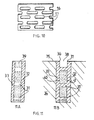
- FIG. 10 shows such an insert 16 provided with a plurality of orifices 17 of almost rectangular shape; these 2x5 mm orifices can be obtained, for example, by means of a laser cutting process or by punching. Then, these spacers 16 are put in place in the cuts made in the unvulcanized tread
- This tread is then placed on a tire blank not vulcanized before being molded with the tire in a vulcanization mold.
- the rubber of the strip passes through the inserts at the locations of the orifices to form the connecting elements of the cutouts, said cutouts being filled with the material of the spacers.
- the circumferential grooves and incisions devoid of connection were made by cutting after manufacturing the tires comprising the treads.
- the additional grooves and incisions can be produced by the process according to the invention.
- the tires chosen were heavyweight tires of size 215/75 R 17.5 , the incisions of which had connecting elements had a connection rate T P equal to 45% and for which the ratios S I / O T and S I / O G were 45% and 40% respectively.
- the notching rates of the rolling surfaces in new condition of the two variants A and B were 15% and 18% respectively (by rate of notching, one understands the ratio between the surface of the cutouts on the rolling surface and the total surface of said rolling surface).
- Grip tests were carried out with a heavy goods vehicle equipped with an additional wheel intended for measurements, said wheel being fitted with a tire according to variant A or according to variant B.
- the appearance of the tire sliding relative to the road is determined for a given speed and under the action of a determined braking force; this test is carried out on a test track having a smooth coating and on which is present a layer of water with a thickness of approximately 1.5 mm.
- a tire of type XZE, of the same dimension and having a cut rate of 18% was taken as a reference base.
- the notching rates of variants A and B are comparable to that of the tire chosen as a reference.
- the results of the grip tests showed that, compared to the reference tire, the tires of variant A were better than the reference tires by around 15% , while the tires of variant B were very at least 30% higher than the reference tires .
- the difference in performance between variants A and B can be partly explained by the difference in width of the incisions.
- the tread according to the invention and the method of manufacturing such a strip make it possible to obtain, with a low rate of notching, that is to say a ratio between the surface corresponding to the cutouts and the total surface of said strip intended to be in contact with the ground, a performance at least equivalent to a strip of usual bearing with a higher rate of notching; the large number of edges of rubber, combined with the fact that the stiffness of the tread is not affected by significantly compensates for the gap in the notch rates.
- connecting elements in the cutouts allows maintain a stiffness in the tread which results in a loss of strength rolling (energy dissipated during the rolling of a tire equipped with said strip) which is significantly less than that obtained with the same tire whose connecting elements have been eliminated.
- the cutouts provided with connecting elements are entirely located under the tread surface of the tread. new and that a plurality of cutouts without connecting elements and at least slightly greater in depth than the distance separating the rolling surface from the cutouts provided with connecting elements is provided on said rolling surface.
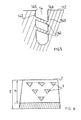
- FIG. 8 shows a schematic section of a tread 26 in new condition comprising a plurality of incisions 27 provided with a plurality of connecting elements 28 .
- the running surface is provided with a plurality of cutouts 29 of shallow depth intended to play an active role in the first times of use of the tread. After partial wear of the strip, the incisions 29 disappear to make way for the underlying incisions 27.
- An alternative embodiment of the spacers consists of using a material in the form of a fabric comprising warp threads and weft threads, said fabric having the property of resisting the vulcanization of said strip and of being able gradually eliminate during rolling of the tire, the spaces delimited by the weft threads and the warp threads allowing the molding of the connecting elements of said cutout.
- the material constituting the spacers can also be formed of one or several wires forming a network of wires which can be eliminated entirely after vulcanization of the tread or gradually during rolling.
- the manufacturing method according to the invention also allows cuts to be made, the walls of which are covered with a mixture of rubber different from the mixture constituting the rest of the tread, as shown in FIG. 11 , in the particular case of an incision provided with connecting elements; of course, the method which is described for forming this type of incision is also applicable to an incision not provided with connecting elements.
- a variant of this process initially consists of forming a stack composed of a non-perforated interlayer and covered on both sides with two layers of raw gum and secondly to pierce said stack according to its thickness before inserting said stack into a strip of raw gum and finally proceed with molding and vulcanization of said strip.
- the gum component the tread occupies each hole and forms each element connecting the cut thus molded.
- the interlayer 39 After vulcanization, one can eliminate, at least on the surface, the material constituting the interlayer 39 as that is visible on the figure 11-B.
- the interlayer is coated with rubber compounds which may be of the same nature as the constituent mixture of the tread, or else of a different nature. A mixture of different types gives the cutting edges better resistance to abrasion resulting from contact with the road. It can also be envisaged to use two layers of rubber compound of different nature on either side of the interlayer to take account, in particular, of a preferential direction of rolling of the tire. In addition, the layers may have different thicknesses and greater than the thickness of the interlayer. Each layer of rubber covering the interlayer may be formed from one or more layers of mixture.
- At least one cutout provided with at least one element connecting element has at least one connecting element formed from a mixture of natural rubber and different mechanical characteristics of the mixture making up the tread.
- a tire can have at the same time a plurality of certain incisions of them being provided with connecting elements and the others not, said incisions being formed for example according to one of the processes which have just been described.
- the field of application of the present invention relates to all types of tires and in particular road type tires, whether intended for equip vehicles such as passenger cars, vans, heavy goods vehicles and including metro tires. More specifically, tires intended to equip the driving axles of heavy goods vehicles have their characteristics significantly improved grip and noise when provided with a band bearing according to the invention.
- the application of a sculpture according to the invention to tires for civil engineering vehicles and more particularly of standard vehicles "dumper" is beneficial since it makes it possible to produce a tread with a plurality of cutouts while ensuring sufficient rigidity for said strip under the crushing forces and motor or braking forces.
- the best performance is obtained when at least 80% of the incisions provided with connecting elements according to the invention each have a width at least equal to 0.1 mm and at least more equal to 2 mm.
- a tread according to the invention can also be placed on a tire blank before being vulcanized with said tire blank in a suitable vulcanization mold.
- a strip according to the invention can comprise a plurality of blocks of rubber delimited by grooves, said blocks comprising at least one incision itself provided with at least one connecting element between the main walls of said incision; the grooves can also be provided with connecting elements so as to make a very efficient sculpture.
Landscapes
- Engineering & Computer Science (AREA)
- Mechanical Engineering (AREA)
- Tires In General (AREA)
- Tyre Moulding (AREA)
- Heating, Cooling, Or Curing Plastics Or The Like In General (AREA)
- Moulds For Moulding Plastics Or The Like (AREA)
- Steps, Ramps, And Handrails (AREA)
Abstract
Description
L'invention concerne les bandes de roulement destinées à la fabrication de pneumatiques neufs ou au rechapage de pneumatiques, et en particulier les sculptures pour lesdites bandes comportant un grand nombre de découpures se présentant sous la forme de rainures et/ou d'incisions. Elle concerne aussi un procédé de fabrication permettant de réaliser de telles bandes.The invention relates to treads intended for the manufacture of new tires or retreading tires, and in particular treads for said strips comprising a large number of cutouts occurring under the form of grooves and / or incisions. It also relates to a manufacturing process allowing such bands to be produced.
Pour adapter la performance des pneumatiques aux performances sans cesse améliorées des nouveaux véhicules, il devient, entre autre, nécessaire d'augmenter le niveau de la performance d'adhérence des pneumatiques sur route mouillée sans pour autant dégrader leurs autres performances. Par adhérence, on entend aussi bien les caractéristiques d'adhérence du pneumatique dans la direction transversale au déplacement du véhicule (tenue en virage) que celles du pneumatique dans la direction longitudinale au déplacement du véhicule (possibilité de transmettre au sol un effort freineur ou moteur).To adapt tire performance to performance constantly new vehicles, it becomes, among other things, necessary to increase the level of grip performance of tires on wet roads without as much to degrade their other performances. By adhesion, we mean both grip characteristics of the tire in the transverse direction to the movement of the vehicle (cornering) than that of the tire in the direction longitudinal to the movement of the vehicle (possibility of transmitting a force to the ground brake or motor).
Afin d'augmenter le potentiel d'adhérence d'une bande de roulement d'un pneumatique roulant sur une route revêtue d'eau, il est connu de pourvoir cette bande d'une sculpture formée d'une pluralité de découpures réalisées plus ou moins profondément dans ladite bande, lesdites découpures débouchant sur la surface de ladite bande en contact avec la route (cette surface est dite surface de roulement).In order to increase the grip potential of a tread of a tire rolling on a road coated with water, it is known to provide this strip of a sculpture formed by a plurality of cutouts made more or less deep into said strip, said cutouts opening onto the surface of said strip strip in contact with the road (this surface is called the rolling surface).
Par découpure, on entend tout évidement réalisé dans la bande de roulement que ce soit par enlèvement de matière une fois la bande vulcanisée ou que ce soit par moulage dans un moule pour mouler ladite bande et comportant des éléments de moulage faisant saillie sur la surface de moulage dudit moule, chaque élément de moulage ayant une géométrie identique à la géométrie de la découpure souhaitée. En règle générale, une découpure réalisée dans une bande de roulement est délimitée par au moins deux parois de gomme se faisant face, lesdites parois étant séparées d'une distance moyenne représentant la largeur de la découpure, l'intersection desdites parois avec la surface de roulement formant des arêtes de gomme. On distingue plusieurs types de découpures, par exemple :
- des rainures ou sillons caractérisés par une largeur supérieure à environ 10% de l'épaisseur de la bande de roulement;
- des incisions de largeur relativement faible comparée à l'épaisseur de la bande de roulement; sous certaines conditions de sollicitation, ces incisions peuvent se fermer, au moins partiellement, dans le contact avec la route; les parois en vis-à-vis viennent en contact l'une contre l'autre au moins sur une partie plus ou moins grande des surfaces desdites parois (les arêtes formées par une incision sur la surface de roulement sont en contact ce qui entraíne la fermeture de l'incision).
- grooves or grooves characterized by a width greater than about 10% of the thickness of the tread;
- relatively small width incisions compared to the thickness of the tread; under certain loading conditions, these incisions can close, at least partially, in contact with the road; the facing walls come into contact with each other at least over a more or less large part of the surfaces of said walls (the edges formed by an incision on the rolling surface are in contact which causes the closing the incision).
Certaines découpures peuvent déboucher dans au moins une autre découpure. La trace d'une découpure sur la surface de roulement d'une bande de roulement suit un profil géométrique moyen déterminé comme le profil géométrique situé à une distance moyenne des arêtes formées par les parois de ladite découpure sur la surface de roulement. L'axe moyen de la trace d'une découpure sur la surface de roulement correspond à la droite des moindres carrés des distances des points du profil moyen de la trace de ladite découpure. En outre, il est usuel de définir le taux d'entaillement d'une sculpture comme le rapport suivant : aire des découpures sur la surface de roulement divisée par l'aire totale de contact entre le pneumatique et la route.Certain cuts can lead to at least one other cut. The trace of a cut on the tread surface of a tread follows a profile geometric mean determined as the geometric profile located at a distance average of the edges formed by the walls of said cutout on the surface of rolling. The middle axis of the trace of a cut on the running surface corresponds to the line of least squares of the distances of the points of the mean profile of the trace of said cut. In addition, it is usual to define the rate of notching of a sculpture like the following report: area of cutouts on the running surface divided by the total contact area between the tire and the road.
En réalisant une pluralité de découpures débouchant sur la surface de roulement, on crée une pluralité d'arêtes de gomme pour couper la couche d'eau éventuellement présente sur la route, de manière à maintenir le pneumatique en contact avec le sol et à créer des cavités formant des canaux destinées à recueillir et à évacuer l'eau présente dans la zone de contact du pneumatique avec la route dès lors qu'elles sont disposées de façon à déboucher en dehors de la zone de contact.By making a plurality of cutouts opening onto the running surface, creates a plurality of eraser edges to possibly cut the layer of water present on the road, so as to keep the tire in contact with the ground and create cavities forming channels intended to collect and evacuate the water present in the contact area of the tire with the road as soon as they are arranged so to lead out of the contact area.
On trouve un exemple d'une telle sculpture dans le brevet US 1,452,099 qui décrit une bande de roulement pourvue d'une pluralité d'incisions d'orientation transversale régulièrement espacées.An example of such a sculpture is found in US Patent 1,452,099 which describes a tread provided with a plurality of incisions of transversely oriented transverse orientation regularly spaced.
Toutefois, l'augmentation du nombre de découpures conduit rapidement à une diminution sensible de la rigidité de la bande de roulement, ce qui a une incidence défavorable sur les performances du pneumatique voire même sur l'adhérence. Par rigidité de la bande de roulement, on entend la rigidité de la bande sous les actions combinées d'efforts de compression et d'efforts de cisaillement dans la région affectée par le contact avec la route. Conjointement, la présence de nombreuses découpures formant des canaux d'évacuation de l'eau induit un niveau de bruit en roulage sur route sèche qui est aujourd'hui considéré comme une nuisance que l'on désire réduire le plus possible tout particulièrement sur les véhicules de conception récente. Ce bruit en roulage est amplifié par les mouvements cycliques de fermeture et d'ouverture des découpures associés au frottement des parois desdites découpures lorsqu'elles sont fermées.However, the increase in the number of cutouts quickly leads to a significant reduction in tread stiffness, which has an impact unfavorable on the performance of the tire or even on the grip. Through tread stiffness means the stiffness of the tread under the actions combined compressive and shear forces in the region affected by contact with the road. Jointly, the presence of numerous cutouts forming water drainage channels induces a noise level when driving on dry roads which is now considered a nuisance that we want to reduce as much as possible particularly on newly designed vehicles. This rolling noise is amplified by the cyclic movements of closing and opening of the cutouts associated with the friction of the walls of said cutouts when they are closed.
Dans le brevet FR 1 028 978, il est proposé une solution à ce problème consistant à pourvoir la bande de roulement d'une pluralité d'incisions circonférentielles de faible profondeur sur la surface de roulement de la bande neuve de façon à augmenter la souplesse de ladite bande uniquement au voisinage de la surface de roulement.In patent FR 1 028 978, a solution is proposed to this problem consisting in providing the tread with a plurality of circumferential incisions of shallow depth on the tread surface of the new band so as to increase the flexibility of said strip only in the vicinity of the running surface.
Cependant, le pneumatique étant destiné, une fois monté sur un véhicule, à assurer une bonne performance pendant toute la durée de vie dudit pneumatique (c'est à dire jusqu'à usure de sa bande de roulement correspondant au moins au niveau légal admis) il est nécessaire de prévoir une bande de roulement dont la sculpture assure la pérennité de la performance d'adhérence sur sol mouillé.However, the tire being intended, once mounted on a vehicle, to ensure good performance throughout the life of said tire (i.e. until the wear of its tread corresponding at least to the legal level allowed) it it is necessary to provide a tread whose tread ensures the durability of grip performance on wet surfaces.
Le document EP-A-0 342 908, qui est un document de l'état de la technique antérieur pertinent, décrit une bande de roulement dont les caractéristiques correspondent à celles du préambule de la revendication 1.EP-A-0 342 908, which is a document of the state of the art relevant prior, describes a tread whose characteristics correspond to those of the preamble of claim 1.
L'objet de la présente invention est d'élaborer une bande de roulement pour pneumatique qui concilie à la fois un très bon niveau d'adhérence sur route mouillée et sur route sèche avec une faible émission de bruit en roulage à l'état neuf et pendant au moins une grande partie de la durée de vie de ladite bande. De façon complémentaire, l'un des objectifs de l'invention est de maítriser l'évolution des performances avec l'usure de la bande de roulement.The object of the present invention is to develop a tread for tire which combines both a very good level of grip on wet roads and on dry roads with low noise emission when driving in new condition and during minus a large part of the life of said strip. In addition, one of the objectives of the invention is to control the evolution of performance with wear of the tread.
Selon l'invention, il est proposé une bande de roulement d'épaisseur E en mélange de caoutchouc, destinée à être placée radialement à l'extérieur d'un pneumatique, ladite bande étant pourvue d'une surface de roulement destinée à venir en contact avec la route pendant le roulage du pneumatique. La bande de roulement est pourvue d'un grand nombre de découpures de façon qu'une pluralité de découpures soient affectées par la zone de contact du pneumatique avec la route, Chaque découpure est définie par l'espace délimité principalement entre deux parois en regard l'une de l'autre, lesdites parois étant perpendiculaires à ou obliques par rapport à la surface de roulement, et chaque découpure a une profondeur au plus égale à l'épaisseur E de la bande de roulement, la profondeur de ladite découpure étant mesurée comme la distance, suivant une direction radiale, des points du contour de ladite découpure les plus éloignés de la surface de roulement du pneumatique neuf par rapport à ladite surface. En outre, deux parois principales d'au moins une découpure située dans la partie de la bande de roulement affectée par l'écrasement au sol du pneumatique en roulage sont reliées par au moins un élément de liaison en gomme.According to the invention, there is provided a tread of thickness E made of a rubber mixture, intended to be placed radially outside a tire, said strip being provided with a tread surface intended to come into contact. with the road while the tire is running. The tread is provided with a large number of cutouts so that a plurality of cutouts are affected by the area of contact of the tire with the road. Each cutout is defined by the space delimited mainly between two facing walls l 'from one another, said walls being perpendicular to or oblique with respect to the running surface, and each cut has a depth at most equal to the thickness E of the tread, the depth of said cut being measured as the distance, in a radial direction, of the points of the contour of said cutout furthest from the running surface of the new tire with respect to said surface. In addition, two main walls of at least one cutout located in the part of the tread affected by the crushing of the tire on the ground while running are connected by at least one rubber connecting element.
On note SE la surface totale de liaison sur chacune des parois de ladite découpure égale soit à la surface totale d'intersection de l'élément de liaison dans le cas d'un élément unique soit à la somme des surfaces d'intersection de tous les éléments de liaison dans le cas de plusieurs éléments et ST la surface totale de chacune des parois principales de ladite découpure.We denote by S E the total connection surface on each of the walls of said cut-out equal either to the total intersection surface of the connection element in the case of a single element or to the sum of the intersection surfaces of all the connecting elements in the case of several elements and S T the total area of each of the main walls of said cutout.
La bande de roulement selon l'invention est caractérisée en ce que :
- les deux parois principales d'au moins une découpure située dans la partie de la bande de roulement affectée par l'écrasement au sol du pneumatique en roulage sont reliées par au moins un élément de liaison en gomme, le (les) élément(s) de liaison présentant avec chacune des parois une surface de liaison SE correspondant à la somme des surfaces d'intersection de chaque élément de liaison, ladite surface SE sur chacune des parois étant au moins égale à 10% de la surface ST de ladite paroi,
- tous les points du contour extérieur de la surface d'intersection d'au moins un élément de liaison avec l'une des parois sont situés à une distance de la surface de roulement strictement inférieure à la profondeur de la découpure,
- et en ce que, sur chacune des parois principales, la surface de liaison SE est au plus égale à 80% de la surface SG , la surface SG étant égale à la surface, mesurée sur ladite paroi de la découpure, délimitée par le contour géométrique L de longueur minimum tracé sur ladite paroi et enveloppant la surface de liaison SE .
- the two main walls of at least one cutout located in the part of the tread affected by the crushing of the tire on the ground while running are connected by at least one rubber connecting element, the element (s) connecting with each of the walls a connecting surface S E corresponding to the sum of the intersection surfaces of each connecting element, said surface S E on each of the walls being at least equal to 10% of the surface S T of said wall,
- all the points of the external contour of the intersection surface of at least one connecting element with one of the walls are located at a distance from the rolling surface strictly less than the depth of the cut,
- and in that, on each of the main walls, the connecting surface S E is at most equal to 80% of the surface S G , the surface S G being equal to the surface, measured on said wall of the cutout, delimited by the geometric contour L of minimum length drawn on said wall and enveloping the connection surface S E.
Pour une paroi, le contour géométrique L de longueur minimum et enveloppant la surface totale de liaison SE sur cette paroi, correspond au contour qui peut être tracé sur ladite paroi de façon à envelopper l'ensemble de la surface totale de liaison formée par les surfaces d'intersection de tous les éléments de liaison avec ladite paroi. Une découpure étant définie comme l'espace continu délimité par au moins deux parois principales en regard l'une de l'autre, la présence d'au moins un élément de liaison entre lesdites parois, selon l'invention, ne rompt pas la continuité de cet espace et ceci quel que soit le niveau d'usure de la bande de roulement comportant une telle découpure.For a wall, the geometric contour L of minimum length and enveloping the total connection surface S E on this wall, corresponds to the contour which can be traced on said wall so as to envelop the whole of the total connection surface formed by the intersection surfaces of all the elements for connection with said wall. A cutout being defined as the continuous space delimited by at least two main walls facing each other, the presence of at least one connecting element between said walls, according to the invention, does not break the continuity of this space and this regardless of the level of wear of the tread comprising such a cutout.
Avantageusement, l'effet sur la performance en adhérence et en bruit est d'autant plus significatif qu'un plus grand nombre de découpures formant la sculpture d'une bande de roulement pour pneumatique sont pourvues d'au moins un élément de liaison de gomme de manière à obtenir à la fois une performance remarquable en adhérence sans pour autant dégrader le niveau de performance en bruit de roulage.Advantageously, the effect on the adhesion and noise performance is all the more more significant than a greater number of cutouts forming the sculpture of a band tire bearings are provided with at least one connecting element rubber so as to obtain both a remarkable performance in adhesion without however degrading the level of performance in road noise.
De manière avantageuse, et pour obtenir un effet de liaison optimum entre les parois des découpures et une longueur d'arêtes de gomme suffisante, chaque surface SG délimitée par le contour géométrique L de longueur minimum et enveloppant la surface totale de liaison SE sur une paroi principale d'une découpure est au moins égale à 15% de la surface de la paroi ST correspondante. Préférentiellement, la surface totale de liaison SE sur au moins une paroi principale d'au moins une découpure est au plus égale à 80% de la surface de la paroi ST correspondante, de manière à conserver un volume de découpure conférant à la bande de roulement des caractéristiques d'adhérence suffisantes.Advantageously, and in order to obtain an optimum bonding effect between the walls of the cutouts and a sufficient length of rubber edges, each surface S G delimited by the geometric contour L of minimum length and enveloping the total bonding surface S E on a main wall of a cutout is at least equal to 15% of the surface of the corresponding wall S T. Preferably, the total connecting surface S E on at least one main wall of at least one cutout is at most equal to 80% of the surface of the corresponding wall S T , so as to maintain a cutout volume giving the strip of sufficient grip characteristics.
La bande de roulement conforme à l'invention présente plusieurs avantages :
- pour les découpures orientées essentiellement transversalement par rapport à la direction longitudinale de la bande, les impacts des arêtes de gomme sur la route sont réduits ce qui se traduit par une atténuation sensible du bruit émis en roulage et cela malgré une quantité d'arêtes relativement importante;
- en sortie d'aire de contact, la présence de éléments de liaison entre les parois des incisions orientées transversalement et éventuellement entre les faces opposées des éléments de relief limite les mouvements d'oscillation des éléments de gomme de la sculpture sortant de ladite aire qui provoquent des vibrations génératrices de bruit, réduisant ainsi le bruit résultant de ces vibrations;
- la réduction de la composante bruit résulte aussi de la diminution du frottement des parois des incisions l'une sur l'autre au passage dans le contact; les éléments de liaison empêchant à la fois le rapprochement des parois et le mouvement relatif de l'une par rapport à l'autre;
- un gain très marqué en adhérence tout en conservant une grande surface de gomme à user dans le cas d'une pluralité d'incisions de largeur faible, lesdites incisions étant pourvues d'au moins un élément de liaison.
- for the cuts oriented essentially transversely to the longitudinal direction of the strip, the impacts of the rubber edges on the road are reduced, which results in a significant attenuation of the noise emitted during driving, despite a relatively large number of edges ;
- at the exit from the contact area, the presence of connecting elements between the walls of the incisions oriented transversely and possibly between the opposite faces of the relief elements limits the oscillating movements of the rubber elements of the sculpture leaving said area which cause noise-generating vibrations, thereby reducing the noise resulting from these vibrations;
- the reduction of the noise component also results from the reduction of the friction of the walls of the incisions one on the other when passing through the contact; the connecting elements preventing both the approximation of the walls and the relative movement of one relative to the other;
- a very marked gain in adhesion while retaining a large surface of rubber to be used in the case of a plurality of incisions of small width, said incisions being provided with at least one connecting element.
Globalement, les sources de bruit associées à une telle sculpture sont beaucoup moins énergétiques du fait de la réduction de mouvement des parois des découpures résultant de la présence des éléments de liaison entre lesdites parois comparativement à une sculpture qui comporterait les mêmes découpures sans aucun élément de liaison.Overall, the sources of noise associated with such a sculpture are many less energetic due to the reduced movement of the cutout walls resulting from the presence of the connecting elements between said walls compared to a sculpture which would include the same cutouts without any connecting element.
Il va de soi qu'une sculpture selon l'invention peut combiner à la fois une pluralité de découpures pourvues d'au moins un élément de liaison avec une pluralité de découpures dépourvues d'élément de liaison, la proportion entre lesdites découpures pouvant être par exemple fonction du type de pneumatique comportant ladite sculpture.It goes without saying that a sculpture according to the invention can combine both a plurality cutouts provided with at least one connecting element with a plurality of cutouts without a connecting element, the proportion between said cutouts may for example be a function of the type of tire comprising said tread.
La demanderesse a obtenu de manière surprenante de très bons résultats en roulage avec des pneumatiques pourvus d'une bande de roulement d'épaisseur E, pourvue d'une pluralité de découpures orientées quasiment dans la même direction, chacune desdites découpures étant définie par l'espace délimité principalement entre deux parois en regard l'une de l'autre, lesdites parois étant perpendiculaires à ou obliques par rapport à la surface de roulement, et lesdites découpures ayant une profondeur h.The Applicant has surprisingly obtained very good rolling results with tires provided with a tread of thickness E, provided with a plurality of cutouts oriented almost in the same direction, each of said cutouts being defined by the space defined mainly between two walls facing each other, said walls being perpendicular to or oblique with respect to the rolling surface, and said cutouts having a depth h .
Par profondeur h d'une découpure, on entend la distance radiale maximale mesurée entre l'arête de la découpure la plus proche de la surface de roulement de la bande de roulement à l'état neuf et le/les point(s) des parois de la découpure le/les plus éloigné(s) radialement de ladite surface de roulement. Cette profondeur h représente la distance radiale maximale existant entre les points les plus éloignés radialement des parois d'une découpure et est au plus égale à l'épaisseur E de la bande de roulement.By depth h of a cut, is meant the maximum radial distance measured between the edge of the cut closest to the running surface of the tread in new condition and the point (s) of the walls. of the cutout the farthest radially from said rolling surface. This depth h represents the maximum radial distance existing between the points radially furthest from the walls of a cutout and is at most equal to the thickness E of the tread.
En outre, la bande de roulement selon une variante de l'invention est telle que :
- les deux parois principales desdites découpures sont reliées par au moins un élément de liaison en gomme;
- le taux de liaison TP=SE/ST, SE pour chaque découpure est au moins égal à 0,10 et au plus égal à 0,80, SE étant égale à la surface totale d'intersection du/des élément(s) de liaison sur chacune des parois, ST représentant la surface totale de chaque paroi principale de ladite découpure;
- le rapport p/h, entre le pas moyen p séparant chacune desdites découpures et leur profondeur h, est au moins égal à 0,2 et au plus égal à 1,9.
- the two main walls of said cutouts are connected by at least one rubber connecting element;
- the connection rate T P = S E / S T , S E for each cut is at least equal to 0.10 and at most equal to 0.80, S E being equal to the total area of intersection of the element (s) (s) of connection on each of the walls, S T representing the total area of each main wall of said cutout;
- the ratio p / h, between the average pitch p separating each of said cutouts and their depth h, is at least equal to 0.2 and at most equal to 1.9.
Pour éviter l'apparition d'usure irrégulière de la bande de roulement et si on se fixe
une valeur du taux de liaison TP des découpures, alors il est préférable de choisir le pas p
de manière à ce que le rapport p/h vérifie, à l'état neuf, l'inégalité suivante :
De façon complémentaire, et pour atteindre une bonne performance en adhérence, il
est judicieux de choisir le pas p de manière à que le rapport p/h vérifie l'inégalité
suivante :
Il est également possible de tenir compte la largeur moyenne e des découpures
(c'est-à-dire la distance moyenne séparant les parois principales desdites découpures)
disposées régulièrement suivant un pas p sur une bande de roulement de manière à
obtenir le taux de liaison Tp permettant d'atteindre de bons résultats en roulage. La
demanderesse a trouvé que des bons résultats en adhérence et en usure sont obtenus
lorsque le taux de liaison Tp est au moins égal à 0,10 et est au plus égal à la valeur
suivante :
Dès que le taux de liaison TP est inférieur à environ 0,10, l'objectif ne peut être atteint car les éléments de liaison n'apportent pas suffisamment de rigidité et ne peuvent pas bloquer suffisamment les mouvements des parois de la découpure auxquelles ils sont liés; préférentiellement, le taux de liaison TP est supérieur à 0,25. As soon as the connection rate T P is less than about 0.10, the objective cannot be achieved because the connection elements do not provide enough rigidity and cannot sufficiently block the movements of the walls of the cut-out to which they are linked; preferentially, the rate of binding T P is greater than 0.25.
À l'opposé, quand ce taux dépasse la valeur limite proposée, la rigidité devient trop importante et la longueur d'arête active est trop réduite pour maintenir une performance satisfaisante en adhérence. Par longueur d'arête active d'une bande de roulement d'un pneumatique, on entend la somme des longueurs de toutes les arêtes de gomme en contact avec la route dans l'empreinte et pour un niveau d'usure de la bande de roulement donné.Conversely, when this rate exceeds the proposed limit value, the stiffness becomes too large and the active edge length is too short to maintain performance satisfactory in adhesion. By active edge length of a tread of a pneumatic, we mean the sum of the lengths of all the rubber edges in contact with the road in the footprint and for a level of tread wear given.
En outre, et afin de conserver une performance suffisamment constante avec l'usure de la bande de roulement, il est judicieux de prévoir que la valeur du taux de liaison TP=SP/ST , évalué pour différents niveaux d'usure de la bande de roulement diminue de façon sensiblement régulière avec l'usure du pneumatique, au moins à partir d'un niveau d'usure partiel prédéterminé, SP représentant, sur une des parois de ladite découpure, la surface de liaison restante après usure partielle de la bande de roulement et ST représentant la surface totale restante de ladite paroi correspondant au même niveau d'usure partielle de la bande de roulement. De cette façon, l'effet des éléments de liaison sur la rigidité est maximum quand la bande de roulement est neuve mais décroít progressivement avec l'augmentation de la rigidité de ladite bande résultant de l'usure.In addition, and in order to maintain a sufficiently constant performance with the wear of the tread, it is wise to provide that the value of the bond rate T P = S P / S T , evaluated for different wear levels of the tread decreases in a substantially regular manner with the wear of the tire, at least from a predetermined partial level of wear, S P representing, on one of the walls of said cutout, the connecting surface remaining after partial wear of the tread and S T representing the total remaining surface of said wall corresponding to the same partial level of wear of the tread. In this way, the effect of the connecting elements on the rigidity is maximum when the tread is new but gradually decreases with the increase in the rigidity of said strip resulting from wear.
D'autre part, des essais de roulage de pneumatiques ont permis de constater que la sculpture selon l'invention conduit à :
- une amélioration de l'usure par la réduction des glissements de la gomme contre la route que ce soit au moment de la sortie de la zone de contact pour les découpures transversales ou que ce soit en régime de virage pour les découpures orientées circonférentiellement;
- une amélioration de la résistance à la fatigue du fond des découpures (c'est à dire de la partie des découpures qui se trouve radialement le plus à l'intérieur de la bande de roulement);
- une moindre rétention de cailloux dans les découpures pourvues d'éléments de liaison.
- an improvement in wear by reducing the slippage of the rubber against the road, whether at the time of leaving the contact zone for transverse cuts or whether it is in a turning regime for circumferentially oriented cuts;
- an improvement in the fatigue strength of the bottom of the cutouts (that is to say of the part of the cutouts which is radially the most inside of the tread);
- less stone retention in cutouts with connecting elements.
On observe, en outre, que le pouvoir drainant de la sculpture selon l'invention, c'est à dire sa capacité à évacuer l'eau présente sur la route, est suffisant et cela quel que soit le niveau d'usure de la bande de roulement, ce qui représente un avantage particulièrement intéressant pour l'utilisateur.We also observe that the draining power of the sculpture according to the invention is to say its capacity to evacuate the water present on the road, is sufficient and that whatever the level of tread wear, which is a particularly advantageous interesting for the user.
Afin d'obtenir une efficacité durable avec le temps en roulage sur une route mouillée d'une sculpture selon l'invention, la longueur d'arête active de la sculpture dans l'empreinte correspondant à chaque niveau d'usure, est définie préférentiellement comme étant au moins égale à 50% de la longueur d'arête active sur la surface de roulement de la bande de roulement à l'état neuf.In order to obtain lasting effectiveness over time while rolling on a wet road of a sculpture according to the invention, the active edge length of the sculpture in the imprint corresponding to each level of wear, is preferably defined as being at least equal to 50% of the active edge length on the running surface of the tread in new condition.
De façon à ce que la bande de roulement conserve une rigidité de cisaillement et de flexion suffisante lorsqu'elle est soumise aux efforts de contact et cela malgré la présence d'un très grand nombre de découpures, il est judicieux de disposer le/les élément(s) de liaison de chacune desdites découpures de manière à ce que la distance séparant l'arête la plus proche de la surface de roulement à l'état neuf et les points du contour de la surface d'intersection dudit élément sur ladite paroi soit au plus égale à 60% de la hauteur h de la découpure et préférentiellement entre 40% et 60%.So that the tread retains sufficient shear and bending rigidity when it is subjected to contact forces and this despite the presence of a very large number of cutouts, it is advisable to arrange the element (s) (S) connecting each of said cutouts so that the distance between the edge closest to the rolling surface in new condition and the points of the contour of the intersection surface of said element on said wall is at most equal to 60% of the height h of the cutout and preferably between 40% and 60% .
Une autre amélioration sensible de la sculpture d'une bande de roulement selon l'invention consiste à réaliser une pluralité de découpures pourvues d'un nombre important d'éléments de liaison répartis de façon assez régulière dans chacune des découpures de façon à assurer une bonne régularité de l'effet induit sur la rigidité des éléments de gomme délimités par les parois de la découpure.Another significant improvement in the tread pattern according to the invention consists in making a plurality of cutouts provided with a number important connecting elements distributed fairly evenly in each of the cuts so as to ensure good regularity of the effect induced on the rigidity of the rubber elements delimited by the walls of the cutout.
Une bande de roulement selon cette dernière amélioration comporte une pluralité de découpures, chaque découpure étant définie par l'espace délimité principalement entre deux parois en regard l'une de l'autre, lesdites parois étant perpendiculaires à ou obliques par rapport à la surface de roulement, et ayant une profondeur, mesurée comme la distance, suivant une direction radiale, des points du contour de ladite découpure les plus éloignés de la surface de roulement du pneumatique neuf, au plus égale à l'épaisseur E de la bande de roulement. La bande est caractérisée en ce que :
- les deux parois principales d'au moins une découpure située dans la partie de la bande de roulement affectée par l'écrasement au sol du pneumatique en roulage sont reliées par une pluralité d'éléments de liaison en gomme, lesdits éléments de liaison présentant avec chacune des parois une surface de liaison SE , ladite surface de liaison SE sur chacune des parois étant au moins égale à 10% de la surface ST de ladite paroi,
- chaque élément de liaison présentant avec chacune des parois une surface d'intersection SE au plus égale à (ExE/20),
- et en ce que la surface SG délimitée par le contour géométrique L de longueur minimum et enveloppant toute la surface de liaison SE est au moins égale à 70% de la surface ST de ladite paroi.
- the two main walls of at least one cutout located in the part of the tread affected by the crushing of the tire on the ground while running are connected by a plurality of rubber connecting elements, said connecting elements having each of the walls a connection surface S E , said connection surface S E on each of the walls being at least equal to 10% of the surface S T of said wall,
- each connecting element having with each of the walls an intersection surface S E at most equal to (ExE / 20) ,
- and in that the surface S G delimited by the geometric contour L of minimum length and enveloping the entire connecting surface S E is at least equal to 70% of the surface S T of said wall.
Cette bande de roulement confère au pneumatique des performances particulièrement homogènes et régulières quel que soit le degré d'usure de ladite bande.This tread gives the tire performance particularly homogeneous and regular whatever the degree of wear of said strip.
Un autre objet de l'invention est de proposer un procédé de fabrication d'une bande de roulement pourvue d'une pluralité de découpures, lesdites découpures étant pourvues d'au moins un élément de liaison. Il ressort clairement que les procédés habituels de moulage des découpures ne sont pas adaptés pour réaliser de telles sculptures de façon aisée et avec une précision suffisante. En effet, le fait de disposer au moins un élément de liaison sous la surface de roulement de la bande de roulement conduit à une impossibilité de démoulage de ladite bande dès lors que l'on emploie un procédé de moulage habituel et mettant en oeuvre des lames métalliques pour mouler des incisions.Another object of the invention is to propose a method of manufacturing a strip bearing provided with a plurality of cutouts, said cutouts being provided at least one connecting element. It is clear that the usual methods of molding of the cutouts are not suitable for making such sculptures so easy and with sufficient precision. Indeed, having at least one element of connection under the running surface of the tread leads to an impossibility for demolding said strip when a conventional molding process is used and using metal blades to mold incisions.
Un objectif de l'invention est de proposer un procédé d'obtention d'une bande pour
pneumatique comportant au moins une découpure dont les parois principales sont reliées
par au moins un élément de liaison en éliminant les problèmes de démoulage. Le procédé
de fabrication d'une bande de roulement d'épaisseur E conforme à l'invention comporte
les étapes suivantes :
Bien entendu, cette bande de roulement peut être réalisée sous la forme d'une bande de longueur prédéterminée ou sous la forme d'un anneau fermé destiné à être placée radialement à l'extérieur de l'ébauche d'un pneumatique au cours de sa fabrication ou sur un pneumatique en cours de rechapage.Of course, this tread can be produced in the form of a strip of predetermined length or in the form of a closed ring intended to be placed radially outside the tire blank during its manufacture or on a tire being retreaded.
Une variante du procédé qui vient d'être décrit peut consister à réaliser les étapes a) à c) et à placer la bande de gomme non vulcanisée et non moulée sur une ébauche de pneumatique avant de procéder au moulage et à la vulcanisation de l'ensemble pneumatique et bande ainsi assemblés.A variant of the process which has just been described may consist in carrying out steps a) to c) and to place the strip of unvulcanized and unmolded gum on a blank of pneumatic before proceeding to the molding and vulcanization of the assembly tire and strip thus assembled.
De façon plus générale, ce procédé, consistant à insérer des intercalaires dans une bande de gomme, peut aussi s'appliquer dans le cas de la fabrication d'une bande de roulement comportant une pluralité d'intercalaires sans orifice pour mouler une pluralité d'incisions ne comportant pas d'éléments de liaison. More generally, this method, consisting of inserting spacers in a rubber band, can also be applied in the case of the manufacture of a rubber band bearing comprising a plurality of tabs without hole for molding a plurality incisions with no connecting elements.
De manière à faciliter l'insertion des intercalaires dans la bande de gomme, il est proposé une autre variante du procédé décrit et consistant à réaliser, dans une bande de gomme non vulcanisée, des découpures de dimensions sensiblement égales aux dimensions des découpures pourvues d'au moins un élément de liaison entre les parois desdites découpures.In order to facilitate the insertion of the spacers in the rubber strip, it is proposed another variant of the process described and consisting in carrying out, in a strip of unvulcanized rubber, cuts of dimensions substantially equal to dimensions of the cutouts provided with at least one connecting element between the walls said cuts.
La matière composant les intercalaires et remplissant les découpures pourvues d'au moins un élément de liaison est choisie de manière à pouvoir être éliminée au moins partiellement, c'est à dire au moins à proximité de la surface de roulement à l'état neuf, et progressivement pendant le roulage pour conserver en permanence une grande longueur d'arêtes.The material composing the spacers and filling the cutouts provided with at least one connecting element is chosen so that it can be eliminated at least partially, i.e. at least close to the rolling surface in new condition, and gradually during taxiing to permanently maintain a long length edges.
La demanderesse a trouvé que la pâte à papier était un matériau de remplissage particulièrement adapté à cet usage, car ce matériau est caractérisé par une très faible cohésion dès lors qu'il est en présence d'eau pendant un laps de temps suffisant et présente donc l'intérêt de pouvoir s'éliminer progressivement pendant le roulage du pneumatique ou bien de pouvoir être éliminé après avoir été mis en présence d'eau et avant tout roulage et cela d'autant plus aisément que les découpures pourvues d'au moins un élément de liaison ont une épaisseur d'au moins 0,4 mm.The Applicant has found that pulp is a filling material which is particularly suitable for this use, because this material is characterized by very low cohesion when it is in the presence of water for a sufficient period of time and therefore presents the advantage of being able to be eliminated progressively during the rolling of the tire or else of being able to be eliminated after being placed in the presence of water and before any rolling, and this all the more easily if the cutouts provided with at least one element of connection have a thickness of at least 0.4 mm.
Une variante de ce procédé consiste à choisir comme matériau composant les intercalaires un matériau dont le point de fusion est suffisamment proche de la température de vulcanisation de ladite bande de façon à devenir fluide seulement vers la fin de la durée de ladite vulcanisation, compte tenu de la montée progressive en température de la gomme constituant ladite bande, de manière à permettre l'enlèvement dudit matériau de remplissage, par exemple par aspiration ou par soufflage après vulcanisation de ladite bande. Préférentiellement, le matériau de remplissage est un alliage ayant un bas point de fusion offrant l'avantage d'être rigide pendant la phase de mise en forme de la bande et pendant la phase de vulcanisation avant de devenir fluide à la fin de la vulcanisation de la bande de façon à permettre l'enlèvement dudit alliage et éventuellement de le recycler pour un usage similaire.A variant of this process consists in choosing as the material composing the inserts a material whose melting point is sufficiently close to the vulcanization temperature of said strip so as to become fluid only towards the end of the duration of said vulcanization, taking into account the gradual rise in temperature of the rubber constituting said strip, so as to allow removal of said filling material, for example by suction or by blowing after vulcanization of said strip. Preferably, the filling material is a alloy with a low melting point offering the advantage of being rigid during the shaping of the strip and during the vulcanization phase before becoming fluid at the end of the vulcanization of the strip so as to allow the removal of said alloy and possibly recycle it for similar use.
Le procédé qui vient d'être décrit peut aussi être suivi d'une opération de meulage affectant quasi uniquement la surface de la bande de roulement neuve et destinée à faire apparaítre de façon très nette une pluralité d'arêtes sur la surface de roulement de ladite bande. Une autre façon d'obtenir un bon état de surface dès la sortie du moule, peut consister à disposer l'ensemble des découpures pourvues d'au moins un élément de liaison sous la surface de roulement de la bande de roulement et à mouler ladite bande dans un moule comportant une pluralité d'éléments de relief destinés à mouler une pluralité de découpures sur la surface de roulement et dont la profondeur est légèrement supérieure à la plus petite des distances séparant les découpures pourvues d'au moins un élément de liaison de la surface de roulement. De cette façon, la bande de roulement en s'usant va révéler progressivement une pluralité de découpures sous la surface de roulement de ladite bande neuve.The process which has just been described can also be followed by a grinding operation. almost exclusively affecting the surface of the new tread intended to make very clearly appear a plurality of edges on the rolling surface of said bandaged. Another way to get a good surface finish right out of the mold, can consist in placing all of the cutouts provided with at least one bond under the tread surface and to mold said tread in a mold comprising a plurality of relief elements intended to mold a plurality of cutouts on the running surface and whose depth is slightly greater than the smallest of the distances separating the cutouts provided with at least one connecting element of the running surface. In this way, the tread in wearing out will gradually reveal a plurality of indentations below the surface of rolling of said new strip.
L'invention sera aisément comprise à l'aide des dessins annexés qui ne représentent que des modes particuliers de réalisation et qui ne sauraient être considérés comme limitatifs.
- la figure 1 est une coupe schématique d'une partie d'une bande de roulement suivant l'invention;
- la figure 2 est une coupe schématique de la bande de roulement de la figure 1 réalisée le long d'une paroi d'une découpure pourvue d'éléments de liaison;
- la figure 3 est une coupe schématique d'une bande de roulement réalisée le long d'une paroi d'une découpure pourvue d'un élément de liaison unique suivant l'invention;
- la figure 4 représente une bande de roulement d'un pneumatique comportant des incisions pourvues d'éléments de liaison, lesdites incisions étant orientées pour une part dans le sens circonférentiel et pour une autre part dans le sens transversal;
- la figure 5 représente la coupe suivant XX de la bande de roulement de la figure 4 montrant une découpure pourvue d'éléments de liaison inclinés par rapport à la surface de roulement de ladite bande;
- la figure 6 représente une variante de disposition des éléments de liaison d'une découpure;
- la figure 7 représente une coupe schématique d'une bande de roulement réalisée le long d'une paroi d'une découpure pourvue d'un grand nombre d'éléments de liaison;
- la figure 8 représente vue en coupe une variante d'une bande de roulement comportant une pluralité d'incisions pourvue d'une pluralité d'éléments de liaison sous la surface de roulement de ladite bande neuve;
- la figure 9 représente deux variantes A et B de sculptures de bande de roulement selon l'invention ayant fait l'objet de tests de roulage;
- la figure 10 représente un intercalaire employé pour la fabrication des variantes A et B de la figure 9;
- la figure 11 représente schématiquement une variante d'une découpure dont les parois principales et les éléments de liaison sont en mélange de gomme de nature différente de la gomme composant la bande de roulement.
- Figure 1 is a schematic section of a portion of a tread according to the invention;
- Figure 2 is a schematic section of the tread of Figure 1 made along a wall of a cutout provided with connecting elements;
- Figure 3 is a schematic section of a tread formed along a wall of a cutout provided with a single connecting element according to the invention;
- FIG. 4 represents a tread of a tire comprising incisions provided with connecting elements, said incisions being oriented partly in the circumferential direction and partly on the transverse direction;
- 5 shows the section along XX of the tread of Figure 4 showing a cutout provided with connecting elements inclined relative to the running surface of said strip;
- FIG. 6 shows a variant arrangement of the connecting elements of a cutout;
- Figure 7 shows a schematic section of a tread made along a wall of a cutout provided with a large number of connecting elements;
- Figure 8 shows a sectional view of a variant of a tread comprising a plurality of incisions provided with a plurality of connecting elements under the tread surface of said new strip;
- FIG. 9 represents two variants A and B of tread patterns according to the invention which have been subject to rolling tests;
- FIG. 10 represents a spacer used for the production of variants A and B of FIG. 9;
- FIG. 11 schematically represents a variant of a cutout, the main walls and the connecting elements of which are in a mixture of rubber of a different nature from the rubber making up the tread.
La bande de roulement 1 représentée partiellement dans le sens de sa longueur sur
la figure 1 a une épaisseur E et une largeur W. Une des parois externes de ladite bande
est destinée à constituer la surface de roulement 2 d'un pneumatique pourvu de ladite
bande; ce pneumatique peut être soit un pneumatique neuf soit un pneumatique rénové
c'est à dire un pneumatique ayant roulé jusqu'à usure de sa bande de roulement
nécessitant alors la mise en place d'une nouvelle bande de roulement.The tread 1 partially shown in the direction of its length in FIG. 1 has a thickness E and a width W. One of the external walls of said strip is intended to constitute the
Une pluralité de découpures 3, 4 sont réalisées dans la bande 1 de façon à s'étendre
sur toute la largeur W de ladite bande 1. La découpure 3 est délimitée par deux parois
principales planes 5, 6 perpendiculaires à la surface de roulement 2 et distantes l'une de
l'autre d'une distance moyenne e égale à la largeur de la découpure 3. Les deux parois 5, 6
délimitant la découpure 3 se raccordent aux points 8 radialement les plus à l'intérieur de
la découpure par rapport à la surface de roulement 2. L'intersection des parois 5, 6 avec la
surface de roulement 2 détermine des arêtes de gomme respectivement 51 et 61 dont une
fonction est de couper le film d'eau pouvant exister entre la bande et la route. A plurality of
La découpure 3 est pourvue de cinq éléments de liaison en gomme 7 qui relient les
parois 5 et 6 de ladite découpure, lesdits éléments de liaison permettant de maintenir à
distance quasiment constante lesdites parois en évitant à la fois l'ouverture et la fermeture
de la découpure 3.The
Sur la figure 2 est représentée une coupe transversale de la bande de roulement 1 de
la figure 1 réalisée le long de la paroi 6 de la découpure 3. On peut y voir, réparties assez
uniformément sur la paroi 6, les surfaces d'intersection 71, 72, 73, 74, 75 des éléments de
liaison 7 avec la paroi 6, la somme desdites surfaces constituant la surface totale
d'intersection SE . Dans le cas présent, tous les éléments de liaison ont leurs surfaces
d'intersection 71, 72, 73, 74, 75 entièrement situées sous la surface de roulement 2 et à
une distance radiale de ladite surface plus petite que la profondeur h de la découpure. De
plus, la surface totale de liaison SE est au plus égale à 80% de la surface SG délimitée par
le contour géométrique L (en traits pointillés) de longueur minimale construit sur la
paroi 6 et enveloppant toutes les surfaces d'intersection 71, 72, 73, 74, 75 des éléments de
liaison 7 avec la paroi 6. Ces trois conditions combinées permettent d'obtenir une
sculpture comportant de très nombreuses découpures sur des profondeurs relativement
importantes comparativement à l'épaisseur de la bande de roulement, lesdites découpures
créant de nombreuses arêtes de gomme sur la surface de roulement 2, ladite sculpture
ainsi réalisée conservant une rigidité suffisante pour résister aux sollicitations dues à
l'écrasement et au roulage.In Figure 2 is shown a cross section of the tread 1 of Figure 1 made along the
De manière connue en soi, les parois principales des découpures peuvent être planes ou bien courbes.In a manner known per se, the main walls of the cutouts can be flat or curved.
Avantageusement et pour obtenir un effet optimum, la bande de roulement comporte une pluralité de découpures pourvue d'au moins un élément de liaison et chaque surface SG , délimitée par le contour géométrique L de longueur minimum et enveloppant la surface totale de liaison SE sur une paroi de la découpure, est au moins égale à 15% de la surface de la paroi ST correspondante.Advantageously and to obtain an optimum effect, the tread comprises a plurality of cutouts provided with at least one connection element and each surface S G , delimited by the geometric contour L of minimum length and enveloping the total connection surface S E on a wall of the cutout, is at least equal to 15% of the surface of the corresponding wall S T.
La position relative des éléments de liaison d'une même découpure est déterminée de manière à maintenir pour ladite découpure une grande longueur d'arête active pour venir en contact avec le sol et cela quel que soit le niveau d'usure de la bande de roulement.The relative position of the connecting elements of the same cutout is determined so as to maintain for said cutout a large active edge length for come into contact with the ground and this regardless of the level of wear of the strip of rolling.
Une autre possibilité de réalisation est représentée sur la figure 3 qui montre la
coupe schématique d'une nervure d'une bande de roulement 1 réalisée le long d'une
paroi 9 d'une découpure pourvue d'un élément de liaison unique 10 s'étendant entre les
parois principales délimitant ladite découpure. Cet élément 10 se compose de deux
branches 101, 102 orientées dans le sens de la largeur de l'incision et reliées entre elles
par une troisième branche 103 orientée dans le sens de l'épaisseur de la bande. Le contour
L tracé en traits pointillés correspond au contour de longueur minimum enveloppant la
surface totale de liaison de l'élément unique et passant par les extrémités des
branches 101 et 102. Une variante de réalisation consiste à prolonger
la branche 103 reliant les branches 101 et 102
jusqu'à la surface de roulement 2 en créant ainsi un
volume unique correspondant à la découpure.Another possible embodiment is shown in Figure 3 which shows the schematic section of a rib of a tread 1 made along a wall 9 of a cutout provided with a single connecting element 10 s' extending between the main walls delimiting said cutout. This
La figure 4 représente partiellement une bande de roulement 11 d'un pneumatique
comportant des incisions orientées dans le sens circonférentiel et des incisions orientées
dans le sens transversal, chacune desdites incisions étant pourvues d'éléments de liaison
et débouchant sur la surface de roulement 112 de ladite bande. La bande de roulement 11
est divisée axialement en trois régions annulaires notées I, II, III, la région médiane II
étant séparée des deux régions bord I et III par des rainures 12 et 13 orientées
circonférentiellement. De manière à améliorer la performance en adhérence du
pneumatique équipé d'une telle bande de roulement sans pour autant être pénalisé en bruit
de roulage, on prévoit dans la partie médiane II une pluralité d'incisions 14 de faible
largeur orientées essentiellement transversalement, lesdites incisions 14 débouchant de
chaque côté de la partie II dans les rainures 12 et 13. Ces incisions 14 de profondeur h et
de largeur e au moins égale à 0,1 mm sont disposées régulièrement selon un pas moyen p
de manière à ce que le rapport h/(p-e) soit plus grand que 0,9. Ainsi, il est possible
d'avoir une densité élevée d'arêtes dans l'empreinte de contact sans qu'il en résulte une
altération des caractéristiques mécaniques de la partie II. FIG. 4 partially represents a
Dans les parties bord I et III, il est prévu au moins une incision 15 orientée
essentiellement dans la direction circonférentielle. Toutes les incisions d'orientation
transversale 14 et les incisions circonférentielles 15 sont pourvues d'une pluralité
d'éléments de liaison respectivement 141 et 151 reliant les parois principales formant
lesdites incisions.In the edge portions I and III , there is provided at least one
Par orientées essentiellement transversalement, on entend que les axes moyens des
traces des incisions sur la surface de roulement 112 font avec la direction transversale de
la bande de roulement un angle au plus égal à 45°. Par orientées essentiellement
circonférentiellement, on entend que les axes moyens des traces des incisions sur la
surface de roulement font avec la direction transversale de la bande de roulement un
angle au moins égal à 75° et au plus égal à 90°. L'axe moyen de la trace d'une découpure
sur la surface de roulement d'une bande de roulement correspond à la direction moyenne
évaluée entre les points des arêtes de ladite découpure sur la surface de roulement à l'aide
d'une méthode des moindres carrés des distances.By oriented essentially transversely, it is meant that the mean axes of the traces of the incisions on the running
De cette façon, il est possible d'obtenir un pneumatique présentant de bonnes performances en adhérence dans le sens longitudinal de la bande de roulement grâce à la présence d'incisions orientées transversalement dans la partie II et en adhérence dans le sens transversal grâce à la présence d'au moins une incision orientée quasiment circonférentiellement dans les parties I et III, lesdites incisions étant pourvues d'éléments de liaison reliant leurs parois.In this way, it is possible to obtain a tire having good performance in grip in the longitudinal direction of the tread thanks to the presence of incisions oriented transversely in part II and in grip in the transverse direction thanks to the presence of at least one incision oriented almost circumferentially in parts I and III, said incisions being provided with connecting elements connecting their walls.
De manière complémentaire, il est possible de prévoir des éléments de liaison reliant aussi les parois délimitant les rainures circonférentielles séparant la partie II des parties I et III. In a complementary manner, it is possible to provide connecting elements also connecting the walls delimiting the circumferential grooves separating part II from parts I and III.
Après usure partielle de la bande de roulement selon l'invention, au moins un
élément de liaison d'une découpure apparaít à la surface de roulement et diminue d'autant
les longueurs des arêtes 145, 146 formées par chacune des parois principales de ladite
découpure avec la surface de roulement 2. Pour atténuer cet effet et comme cela est
montré sur la figure 5, correspondant à une coupe suivant XX de la bande de roulement
représentée sur la figure 4, il est judicieux de disposer chaque élément de liaison 141
entre une première paroi principale 142 et une deuxième paroi principale 143 de la
découpure 14 de façon à ce que ledit élément fasse, avec la perpendiculaire à la surface
de roulement de la bande de roulement neuve, un angle différent de 90° et
préférentiellement entre 30° et 70°.After partial wear of the tread according to the invention, at least one connecting element of a cutout appears on the rolling surface and decreases the lengths of the
Une autre manière de résoudre l'inconvénient qui vient d'être mentionné et
également pour éviter la localisation des usures sur certaines régions d'une bande de
roulement selon l'invention, il est avantageux de prévoir, comme cela est le cas pour les
incisions 14 localisées dans la partie médiane II de la bande de roulement visualisée
figure 4, entre deux quelconques découpures voisines d'orientation sensiblement
identique, un décalage dans le sens radial de la position des éléments de liaison. Ainsi, on
répartit de façon aléatoire la position des arêtes de gomme formées par l'intersection des
parois des découpures. Le fait que les éléments de liaison arrivent à la surface de
roulement après usure de façon plus ou moins décalée permet de maintenir en
permanence (c'est à dire pendant toute la durée de l'utilisation du pneumatique) une
grande longueur d'arêtes dans la région de la surface de roulement affectée par le contact
avec la route et permet de réaliser un brouillage favorable à la fois sur l'usure (on évite
l'apparition d'usures anormales, c'est à dire localisées) et sur le bruit de roulage.Another way to solve the drawback which has just been mentioned and also to avoid the localization of wear on certain regions of a tread according to the invention, it is advantageous to provide, as is the case for the
Dans le cas d'une utilisation faisant essentiellement appel à des caractéristiques d'adhérence dans le sens longitudinal, il est possible de prévoir uniquement une pluralité de découpures pourvues d'au moins un élément de liaison, l'axe moyen des traces desdites découpures sur la surface de roulement du pneumatique formant avec la direction transversale de la bande de roulement un angle au plus égal à 45°. Inversement, dans le cas d'utilisation faisant essentiellement appel à des caractéristiques d'adhérence dans le sens transversal, il est possible de prévoir une pluralité de découpures pourvues d'au moins un élément de liaison, l'axe moyen des traces desdites découpures sur la surface de roulement de ladite bande à l'état neuf forme avec la direction axiale de la bande de roulement un angle au moins égal à 75° et au plus égal à 90°. Un résultat comparable est obtenu en réalisant une seule découpure continue et orientée selon un angle proche de 90° avec la direction transversale de façon à ce que l'axe moyen de la trace de la découpure sur la surface de roulement forme une hélice; en effet, tout se passe dans la zone de contact avec la route comme si la bande était pourvue d'une pluralité de découpures quasiment orientées dans la direction circonférentielle. In the case of a use essentially using characteristics of adhesion in the longitudinal direction, it is possible to provide only a plurality of cutouts provided with at least one connecting element, the mean axis of the traces of said cutouts on the tire rolling surface forming with the transverse direction of the tread an angle at most equal to 45 ° . Conversely, in the case of use essentially using adhesion characteristics in the transverse direction, it is possible to provide a plurality of cutouts provided with at least one connecting element, the mean axis of the traces of said cutouts on the running surface of said strip in the new state forms with the axial direction of the tread an angle at least equal to 75 ° and at most equal to 90 ° . A comparable result is obtained by making a single continuous cut and oriented at an angle close to 90 ° with the transverse direction so that the mean axis of the trace of the cut on the rolling surface forms a helix; in fact, everything takes place in the zone of contact with the road as if the strip were provided with a plurality of cutouts almost oriented in the circumferential direction.
Les découpures pourvues d'au moins un élément de liaison peuvent être perpendiculaires à la surface de roulement ou bien au moins une partie de celles-ci font, avec la direction perpendiculaire à la surface de roulement de la bande de roulement à l'état neuf, un angle moyen au plus égal à 20° de manière à augmenter l'efficacité des arêtes de gomme dans certaines utilisations de façon à pouvoir mieux transmettre un effort moteur ou freineur selon le sens d'orientation choisi de l'inclinaison de ladite découpure.The cutouts provided with at least one connecting element can be perpendicular to the running surface or at least part of these, with the direction perpendicular to the running surface of the tread in new condition , an average angle at most equal to 20 ° so as to increase the efficiency of the rubber edges in certain uses so as to be able to better transmit a motor or braking force depending on the direction of orientation chosen for the inclination of said cutout.
La rigidité de la sculpture d'une bande de roulement augmentant avec la diminution
de son épaisseur résultant de l'usure de ladite bande, il est judicieux de prévoir, en plus,
que pour au moins une découpure, située dans la partie de la bande de roulement affectée
par l'écrasement du pneumatique et pourvue d'au moins un élément de liaison, le rapport
Tp=Sp/St diminue de façon sensiblement régulière avec l'usure du pneumatique au
moins à partir d'un niveau d'usure partiel prédéterminé, Sp représentant, sur une des
parois de ladite découpure, la surface de liaison restante après usure partielle de la bande
de roulement et St représentant la surface totale de ladite paroi correspondant au même
niveau d'usure partielle de la bande de roulement. Dans ce cadre, la figure 6 représente,
vue suivant une coupe transversale, une paroi d'une découpure pourvue d'éléments de
liaison 7 disposés suivant des rangées quasiment parallèles à la surface de roulement 2; le
nombre des éléments de liaison 7 par rangée augmentant au fur et à mesure qu'on se
rapproche de la surface de roulement 2.The rigidity of the tread pattern increasing with the decrease in its thickness resulting from the wear of said strip, it is advisable to provide, in addition, that for at least one cutout, located in the part of the strip of rolling affected by the flattening of the tire and provided with at least one connecting element, the ratio Tp = Sp / St decreases in a substantially regular manner with the wear of the tire at least from a partial level of wear predetermined, Sp representing, on one of the walls of said cutout, the connecting surface remaining after partial wear of the tread and St representing the total surface of said wall corresponding to the same level of partial wear of the tread. In this context, FIG. 6 represents, seen in a cross section, a wall of a cutout provided with connecting
La figure 7 montre une disposition avantageuse en terme de liaison des parois
principales d'une même découpure d'une bande de roulement. Sur cette figure, on voit,
régulièrement réparties sur une paroi principale 66 d'une découpure, une pluralité de
surfaces d'intersection 76 d'éléments de liaison avec ladite paroi de façon que la densité
en éléments de liaison soit relativement importante (c'est à dire qu'il existe un grand
nombre d'éléments par surface de paroi). Dans le cas présent, la surface SG délimitée par
le contour L de longueur minimale et enveloppant toutes les surfaces d'intersection des
éléments de liaison est d'environ 90% de la surface totale de la paroi 66 tandis que la
surface de liaison SE ne représente que 40% de la surface totale. Un effet optimum sur la
rigidité de la bande est atteint quand les éléments de liaison sont régulièrement distribués
sur les parois de chaque découpure.Figure 7 shows an advantageous arrangement in terms of connecting the main walls of the same cut of a tread. In this figure, we can see, regularly distributed over a
En outre et de manière avantageuse, il peut être intéressant de prévoir des éléments supplémentaires en gomme liés à une seule des parois d'une découpure pourvue d'éléments de liaison pour empêcher le rapprochement des régions des parois de ladite découpure situées entre lesdits éléments de liaison.In addition and advantageously, it may be advantageous to provide elements additional rubber bonded to only one of the walls of a cutout provided connecting elements to prevent the regions of the walls of said wall from coming together cutout located between said connecting elements.
La demanderesse a procédé à des essais de roulage et de simulation de roulage avec
des pneumatiques poids-lourd de dimension 215/75 R 17.5 comportant des bandes de
roulement selon l'invention. La figure 9 représente schématiquement deux types de
sculpture de bande de roulement testées. La figure 9-A correspond à la variante A d'une
bande de roulement 18 comportant une pluralité d'incisions 21 de largeur 0,1 mm,
orientées transversalement et espacées circonférentiellement d'un pas moyen p de 15 mm;
cette variante comporte en plus trois rainures circonférentielles 19 de largeur 5 mm qui
divisent axialement la bande de roulement en quatre parties, chacune desdites parties
étant encore divisée en deux par une incision circonférentielle 20 de largeur 2 mm.
Toutes les découpures ont la même profondeur égale à 13,5 mm. La figure 9-B
correspond à la variante B d'une bande de roulement 22 comportant une pluralité
d'incisions 25 de largeur 1mm orientées suivant une direction faisant un angle moyen de
15° avec la direction transversale du pneumatique et espacées les unes les autres d'un pas
p moyen de 10 mm; cette variante B comporte en plus deux rainures 23 de forme ondulée
et essentiellement circonférentielles 19 de largeur 10 mm qui divisent axialement la
bande de roulement en trois parties, chacune desdites parties étant encore divisée en deux
par une incision circonférentielle 24 de largeur 2 mm, lesdites incisions suivant le même
profil que les rainures. Toutes les découpures des deux variantes A et B ont une
profondeur identique et égale en moyenne à 13,5 mm.The Applicant has carried out rolling and rolling simulation tests with truck tires of size 215/75 R 17.5 comprising treads according to the invention. FIG. 9 schematically represents two types of tread pattern tested. FIG. 9-A corresponds to variant A of a
Les variantes A et B ont été réalisées de la manière suivante : après avoir découpée,
suivant les tracés des incisions désirées, une bande de gomme non vulcanisée de largeur
et de longueur appropriées, on réalise, en nombre égal au nombre d'incisions et de
dimensions équivalentes, des intercalaires dans des feuilles de papier d'épaisseur 0,1mm
pour la variante A et dans des feuilles de carton d'épaisseur 1mm pour la variante B.
Chaque intercalaire est ensuite découpé de manière à créer une pluralité d'orifices dont la
forme correspond à la forme des sections des éléments de liaison des incisions. La
figure 10 montre un tel intercalaire 16 pourvu d'une pluralité d'orifices 17 de forme
quasiment rectangulaire; ces orifices de dimension 2x5 mm peuvent être obtenus, par
exemple, au moyen d'un procédé de coupe au laser ou par poinçonnage. Ensuite, ces
intercalaires 16 sont mis en place dans les découpes réalisées dans la bande de roulement
non vulcaniséeVariants A and B were produced in the following manner: after having cut, according to the tracings of the desired incisions, a strip of unvulcanized rubber of appropriate width and length, a number equal to the number of incisions and of equivalent dimensions, dividers in sheets of paper 0.1 mm thick for variant A and in sheets of cardboard 1 mm thick for variant B. Each insert is then cut so as to create a plurality of orifices whose shape corresponds to the shape of the sections of the connecting elements of the incisions. FIG. 10 shows such an
Cette bande de roulement est ensuite placée sur une ébauche de pneumatique non vulcanisée avant d'être moulée avec le pneumatique dans un moule de vulcanisation. Au cours de la vulcanisation de ladite bande, la gomme de la bande traverse les intercalaires aux endroits des orifices pour former les éléments de liaison des découpures, lesdites découpures étant remplies par le matériau constitutif des intercalaires. Pour obtenir les variantes A et B, les rainures et les incisions circonférentielles dépourvues d'éléments de liaison ont été réalisées par taillage après fabrication des pneumatiques comportant les bandes de roulement. Bien entendu, les rainures et incisions supplémentaires peuvent être réalisées par le procédé conforme à l'invention.This tread is then placed on a tire blank not vulcanized before being molded with the tire in a vulcanization mold. At during the vulcanization of said strip, the rubber of the strip passes through the inserts at the locations of the orifices to form the connecting elements of the cutouts, said cutouts being filled with the material of the spacers. To get the variants A and B, the circumferential grooves and incisions devoid of connection were made by cutting after manufacturing the tires comprising the treads. Of course, the additional grooves and incisions can be produced by the process according to the invention.
Dans le cas d'espèce, les pneumatiques choisis étaient des pneumatiques de type poids lourd de dimension 215/75 R 17.5 dont les incisions pourvues d'éléments de liaison avaient un taux de liaison TP égal à 45% et pour lesquelles les rapports SE/ST et SE/SG étaient égaux respectivement à 45% et à 40%. Les taux d'entaillement des surfaces de roulement à l'état neuf des deux variantes A et B étaient respectivement de 15% et de 18% (par taux d'entaillement, on entend le rapport entre la surface des découpures sur la surface de roulement et la surface totale de ladite surface de roulement).In this case, the tires chosen were heavyweight tires of size 215/75 R 17.5 , the incisions of which had connecting elements had a connection rate T P equal to 45% and for which the ratios S I / O T and S I / O G were 45% and 40% respectively. The notching rates of the rolling surfaces in new condition of the two variants A and B were 15% and 18% respectively (by rate of notching, one understands the ratio between the surface of the cutouts on the rolling surface and the total surface of said rolling surface).
Des tests d'adhérence ont été réalisés avec un véhicule poids lourd équipé d'une roue supplémentaire destinée à des mesures, ladite roue étant équipée d'un pneumatique selon la variante A ou selon la variante B. Dans cet essai, on détermine l'apparition du glissement du pneumatique par rapport à la route pour une vitesse donnée et sous l'action d'un effort freineur déterminé; ce test est réalisé sur une piste d'essai ayant un revêtement lisse et sur laquelle est présente une couche d'eau d'épaisseur environ 1,5 mm. Un pneumatique de type XZE, de même dimension et ayant un taux d'entaillement de 18%, a été pris comme base de référence. Les taux d'entaillement des variantes A et B sont comparables à celui du pneumatique choisi comme référence.Grip tests were carried out with a heavy goods vehicle equipped with an additional wheel intended for measurements, said wheel being fitted with a tire according to variant A or according to variant B. In this test, the appearance of the tire sliding relative to the road is determined for a given speed and under the action of a determined braking force; this test is carried out on a test track having a smooth coating and on which is present a layer of water with a thickness of approximately 1.5 mm. A tire of type XZE, of the same dimension and having a cut rate of 18% , was taken as a reference base. The notching rates of variants A and B are comparable to that of the tire chosen as a reference.
De façon inattendue, les résultats des tests d'adhérence ont montré que, comparativement au pneumatique de référence, les pneumatiques de la variante A étaient meilleurs que les pneumatiques de référence d'environ 15%, tandis que les pneumatiques de la variante B étaient très supérieurs aux pneumatiques de référence, d'au moins 30%. L'écart de performance entre les variantes A et B peut s'expliquer en partie par la différence de largeur des incisions.Unexpectedly, the results of the grip tests showed that, compared to the reference tire, the tires of variant A were better than the reference tires by around 15% , while the tires of variant B were very at least 30% higher than the reference tires . The difference in performance between variants A and B can be partly explained by the difference in width of the incisions.
D'autre part, des essais de mesure de bruit émis en roulage dans les conditions définies par la norme ISO 362 ont montré, de façon tout aussi surprenante, que le niveau de bruit émis par un pneumatique pourvu d'une bande de roulement selon l'invention était réduit d'au moins 3 dbA et d'au moins 2 dbA pour les variantes A et B respectivement comparativement aux pneumatiques de référence.On the other hand, tests for measuring the noise emitted during driving under the conditions defined by the ISO 362 standard have shown, just as surprisingly, that the noise level emitted by a tire provided with a tread according to the The invention was reduced by at least 3 dbA and at least 2 dbA for variants A and B respectively compared to the reference tires.
Alors qu'il est connu, dans le cas de sculptures usuelles pour pneumatiques poids lourd, que l'obtention d'une bonne performance en bruit s'accompagne toujours d'une baisse de la performance en adhérence sur sol lisse, ces essais ont montré que grâce à une sculpture de bande de roulement conforme à l'invention, il est possible d'obtenir un gain très net de la performance à la fois en adhérence et en bruit de roulage.While it is known, in the case of usual treads for pneumatic tires heavy, that obtaining a good noise performance is always accompanied by a decrease in grip performance on smooth ground, these tests have shown that thanks to a tread pattern according to the invention, it is possible to obtain a gain very clear performance both in grip and in road noise.
La bande de roulement selon l'invention et le procédé de fabrication d'une telle bande permettent d'obtenir, avec un faible taux d'entaillement, c'est à dire un rapport entre la surface correspondant aux découpures et la surface totale de ladite bande destinée à être en contact avec le sol, une performance au moins équivalente à une bande de roulement usuelle ayant un plus fort taux d'entaillement; le grand nombre d'arêtes de gomme, combiné avec le fait que la rigidité de la bande de roulement n'est pas affectée de manière sensible compense l'écart des taux d'entaillement.The tread according to the invention and the method of manufacturing such a strip make it possible to obtain, with a low rate of notching, that is to say a ratio between the surface corresponding to the cutouts and the total surface of said strip intended to be in contact with the ground, a performance at least equivalent to a strip of usual bearing with a higher rate of notching; the large number of edges of rubber, combined with the fact that the stiffness of the tread is not affected by significantly compensates for the gap in the notch rates.
Il faut noter que la présence d'éléments de liaison dans les découpures permet de conserver à la bande de roulement une rigidité qui se traduit par une perte en résistance au roulement (énergie dissipée au cours du roulage d'un pneumatique équipé de ladite bande) qui est nettement moindre que celle obtenue avec le même pneumatique dont les éléments de liaison ont été éliminés.It should be noted that the presence of connecting elements in the cutouts allows maintain a stiffness in the tread which results in a loss of strength rolling (energy dissipated during the rolling of a tire equipped with said strip) which is significantly less than that obtained with the same tire whose connecting elements have been eliminated.
Après fabrication des pneumatiques pourvus d'une bande de roulement selon l'invention, il est possible d'éliminer partiellement, c'est à dire uniquement au voisinage de la surface de roulement, les intercalaires de façon à dégager les arêtes des incisions sur la surface de roulement. Par la suite, le matériau constituant les intercalaires s'élimine au fur et à mesure de l'usure de la bande de roulement.After manufacturing tires fitted with a tread according to the invention, it is possible to partially eliminate, i.e. only in the vicinity of the running surface, the spacers so as to clear the edges of the incisions on the running surface. Subsequently, the material constituting the spacers is eliminated at the as the tread wears.
De façon à obtenir un meilleur aspect de la bande de roulement en sortie du moule
de vulcanisation de ladite bande, il peut être envisagé de prévoir que les découpures
pourvues d'éléments de liaison soient entièrement situées sous la surface de roulement de
la bande de roulement neuve et qu'il soit prévu sur ladite surface de roulement une
pluralité de découpures sans éléments de liaison et de profondeur au moins légèrement
supérieure à la distance séparant la surface de roulement des découpures pourvues
d'éléments de liaison. Une telle réalisation est visible sur la figure 8 qui montre une coupe
schématique d'une bande de roulement 26 à l'état neuf comportant une pluralité
d'incisions 27 pourvues d'une pluralité d'éléments de liaison 28. La surface de roulement
est pourvue d'une pluralité de découpures 29 de faible profondeur destinées à jouer un
rôle actif dans les premiers temps d'usage de la bande de roulement. Après usure partielle
de la bande, les incisions 29 disparaissent pour laisser la place aux incisions sous-jacentes
27. In order to obtain a better appearance of the tread at the outlet from the vulcanization mold of said tread, it can be envisaged to provide that the cutouts provided with connecting elements are entirely located under the tread surface of the tread. new and that a plurality of cutouts without connecting elements and at least slightly greater in depth than the distance separating the rolling surface from the cutouts provided with connecting elements is provided on said rolling surface. Such an embodiment is visible in FIG. 8 which shows a schematic section of a
Une variante de réalisation des intercalaires consiste à employer un matériau se présentant sous la forme d'un tissu comportant des fils de chaíne et des fils de trame, ledit tissu ayant la propriété de résister à la vulcanisation de ladite bande et de pouvoir s'éliminer progressivement pendant le roulage du pneumatique, les espaces délimités par les fils de trame et les fils de chaíne permettant le moulage des éléments de liaison de ladite découpure. Le matériau constituant les intercalaires peut aussi être formé d'un ou plusieurs fils formant un réseau de fils pouvant s'éliminer en totalité après vulcanisation de la bande de roulement ou bien progressivement au cours du roulage.An alternative embodiment of the spacers consists of using a material in the form of a fabric comprising warp threads and weft threads, said fabric having the property of resisting the vulcanization of said strip and of being able gradually eliminate during rolling of the tire, the spaces delimited by the weft threads and the warp threads allowing the molding of the connecting elements of said cutout. The material constituting the spacers can also be formed of one or several wires forming a network of wires which can be eliminated entirely after vulcanization of the tread or gradually during rolling.
Le procédé de fabrication selon l'invention permet, en outre, de réaliser des découpures dont les parois sont recouvertes d'un mélange de gomme différent du mélange constitutif du reste de la bande de roulement, comme cela est visualisé sur la figure 11, dans le cas particulier d'une incision pourvue d'éléments de liaison; bien entendu, le procédé qui est décrit pour former ce type d'incision est également applicable à une incision non pourvue d'éléments de liaison.The manufacturing method according to the invention also allows cuts to be made, the walls of which are covered with a mixture of rubber different from the mixture constituting the rest of the tread, as shown in FIG. 11 , in the particular case of an incision provided with connecting elements; of course, the method which is described for forming this type of incision is also applicable to an incision not provided with connecting elements.
La figure 11-B montre une variante d'une découpure 38 pourvue d'une pluralité d'éléments de liaison 311 réalisée en suivant les étapes suivantes :
- on réalise au moins un intercalaire 39 comportant une pluralité d'orifices 31 (visibles sur la figure 11-A);
- on forme un empilement en recouvrant au moins un intercalaire sur chacune de ses deux faces principales avec deux couches de gomme crue (32, 33), chaque couche ayant une épaisseur proche de l'épaisseur de l'intercalaire;
- on exerce une pression de part et d'autre de l'empilement ainsi constitué de façon à appliquer plus ou moins fortement chaque couche (32, 33) contre les parois de l'intercalaire et de façon à forcer chaque couche à pénétrer dans les orifices jusqu'à venir en contact l'une avec l'autre; les contacts ainsi formés facilitent la manipulation de l'intercalaire enveloppé de mélange de gomme avant la mise en place dans la découpure prévue dans la bande de roulement crue;
- on insère chaque intercalaire dans une bande de gomme non vulcanisée;
- on procède ensuite à la vulcanisation et au moulage de la bande ainsi constituée dans un moule approprié. Ce moule peut comporter des éléments de relief faisant saillie à sa surface de moulage pour mouler des découpures sous forme de rainures ou incisions.
- at least one
interlayer 39 is produced comprising a plurality of orifices 31 (visible in FIG. 11-A ); - forming a stack by covering at least one interlayer on each of its two main faces with two layers of raw rubber ( 32, 33 ), each layer having a thickness close to the thickness of the interlayer;
- pressure is exerted on either side of the stack thus formed so as to apply more or less strongly each layer ( 32, 33 ) against the walls of the interlayer and so as to force each layer to penetrate into the orifices until coming into contact with each other; the contacts thus formed facilitate the handling of the interlayer wrapped in rubber compound before being placed in the cutout provided in the raw tread;
- each insert is inserted into a strip of unvulcanized rubber;
- then the vulcanization and molding of the strip thus formed are carried out in an appropriate mold. This mold may include relief elements projecting from its molding surface to mold cutouts in the form of grooves or incisions.
Une variante de ce procédé consiste dans un premier temps à former un empilement composé d'un intercalaire non troué et recouvert sur ses deux faces avec deux couches de gomme crue et dans un deuxième temps à trouer ledit empilement suivant son épaisseur avant d'insérer ledit empilement dans une bande de gomme crue et finalement de procéder au moulage et à la vulcanisation de ladite bande. De cette façon, la gomme composant la bande de roulement occupe chaque orifice et vient former chaque élément de liaison de la découpure ainsi moulée. A variant of this process initially consists of forming a stack composed of a non-perforated interlayer and covered on both sides with two layers of raw gum and secondly to pierce said stack according to its thickness before inserting said stack into a strip of raw gum and finally proceed with molding and vulcanization of said strip. In this way, the gum component the tread occupies each hole and forms each element connecting the cut thus molded.
Après vulcanisation, on peut éliminer, au moins en surface, le matériau constituant
l'intercalaire 39 comme cela est visible sur la figure 11-B. L'enrobage de l'intercalaire est
réalisé avec des mélanges de gomme qui peuvent être de même nature que le mélange
constitutif de la bande de roulement ou bien de nature différente. Un mélange de nature
différente confère aux arêtes de la découpure une meilleure résistance à l'abrasion
résultant du contact avec la route. Il peut aussi être envisagé d'employer deux couches de
mélanges de gomme de nature différente de part et d'autre de l'intercalaire pour tenir
compte, notamment, d'un sens de roulage préférentiel du pneumatique. En outre, les
couches peuvent avoir des épaisseurs différentes et supérieures à l'épaisseur de
l'intercalaire. Chaque couche de gomme recouvrant l'intercalaire peut être formée d'une
ou plusieurs couches de mélange.After vulcanization, one can eliminate, at least on the surface, the material constituting the
Il peut être intéressant qu'au moins une découpure pourvue d'au moins un élément de liaison ait au moins un élément de liaison formé en mélange de gomme de nature et de caractéristiques mécaniques différentes du mélange composant la bande de roulement.It may be advantageous for at least one cutout provided with at least one element connecting element has at least one connecting element formed from a mixture of natural rubber and different mechanical characteristics of the mixture making up the tread.
L'ensemble des variantes décrites dans la présente application peuvent faire l'objet de combinaison selon le but recherché. Par exemple, un pneumatique peut comporter à la fois une pluralité d'incisions certaines d'entre-elles étant pourvues d'éléments de liaison et les autres non, lesdites incisions étant formées par exemple selon l'un des procédés qui viennent d'être décrits.All the variants described in this application can be the subject combination according to the desired goal. For example, a tire can have at the same time a plurality of certain incisions of them being provided with connecting elements and the others not, said incisions being formed for example according to one of the processes which have just been described.
Le domaine d'application de la présente invention concerne tous les types de pneumatiques et en particulier les pneumatiques de type routier, qu'ils soient destinés à équiper des véhicules de type voitures de tourisme, camionnettes, poids lourd et notamment des pneumatiques pour métro. Plus spécifiquement , les pneumatiques destinés à équiper les essieux moteur de véhicules poids-lourd ont leurs caractéristiques d'adhérence et de bruit sensiblement améliorées dès lors qu'ils sont pourvus d'une bande de roulement selon l'invention. L'application d'une sculpture suivant l'invention à des pneumatiques pour engins de génie civil et plus particulièrement des véhicules type "dumper" est bénéfique puisqu'elle permet de réaliser une bande de roulement avec une pluralité de découpures tout en assurant une rigidité suffisante à ladite bande sous les efforts d'écrasement et les efforts moteur ou freineur.The field of application of the present invention relates to all types of tires and in particular road type tires, whether intended for equip vehicles such as passenger cars, vans, heavy goods vehicles and including metro tires. More specifically, tires intended to equip the driving axles of heavy goods vehicles have their characteristics significantly improved grip and noise when provided with a band bearing according to the invention. The application of a sculpture according to the invention to tires for civil engineering vehicles and more particularly of standard vehicles "dumper" is beneficial since it makes it possible to produce a tread with a plurality of cutouts while ensuring sufficient rigidity for said strip under the crushing forces and motor or braking forces.
Dans le domaine du pneumatique poids-lourd et tourisme, les meilleures performances sont obtenues dès lors qu'au moins 80% des incisions pourvues d'éléments de liaison selon l'invention ont chacune une largeur au moins égale à 0,1 mm et au plus égale à 2 mm.In the field of truck and passenger car tires, the best performance is obtained when at least 80% of the incisions provided with connecting elements according to the invention each have a width at least equal to 0.1 mm and at least more equal to 2 mm.
Une bande de roulement conforme à l'invention peut aussi être placée sur une ébauche de pneumatique avant d'être vulcanisée avec ladite ébauche de pneumatique dans un moule de vulcanisation approprié.A tread according to the invention can also be placed on a tire blank before being vulcanized with said tire blank in a suitable vulcanization mold.
Enfin, une bande conforme à l'invention peut comporter une pluralité de blocs de gomme délimités par des rainures, lesdits blocs comportant au moins une incision elle-même pourvue d'au moins un élément de liaison entre les parois principales de ladite incision; les rainures peuvent, en outre, être pourvues d'éléments de liaison de façon à réaliser une sculpture très performante.Finally, a strip according to the invention can comprise a plurality of blocks of rubber delimited by grooves, said blocks comprising at least one incision itself provided with at least one connecting element between the main walls of said incision; the grooves can also be provided with connecting elements so as to make a very efficient sculpture.
Claims (46)
- A tread (1, 26) of thickness E for a tyre, provided with a running surface (2), said tread (1) being provided with a plurality of cutouts (3, 4, 27), each cutout (3) being defined by the space defined principally between two opposing walls (5, 6), said walls being perpendicular to or oblique to the running surface (2), and having a depth h, measured as the maximum radial distance measured between the points of the walls of said cutout which are radially farthest away, at most equal to the thickness E of the tread, characterised in that:the two main walls (5, 6) of at least one cutout (3) located in the part of the tread affected by the loading on the ground of the tyre during travel are connected by at least two rubber connecting elements (7), the connecting elements (7) having with each of the walls (5, 6) a connection surface SE corresponding to the total intersection surface, said surface SE on each of the walls being at least equal to 10% of the surface ST of said wall,all the points of the outer contour of the surface of intersection of at least one connecting element (7) with one of the walls (5, 6) are located at a distance from the running surface (2) which is strictly less than the depth of the cutout,and in that, on each of the walls, the connection surface SE is at most 80% of the surface SG, the surface SG being equal to the surface, measured on said wall of the cutout, defined by the geometric contour L of minimum length and enveloping the connection surface SE.
- A tread according to Claim 1, characterised in that, for at least one cutout(3, 4, 27) comprising at least two connecting elements (7), the surface SG defined by the geometric contour L of minimum length and enveloping the total connection surface SE on one main wall of the cutout is at least equal to 15% of the surface ST of the corresponding wall.
- A tread according to one of Claims 1 or 2, characterised in that all the cutouts (3, 4, 27) comprising at least two connecting elements (7, 28) are entirely located beneath the running surface (2) of the tread when new and in that, furthermore, there are provided on the surface of the tread of the new tyre cutouts (29) the depth of which is greater than the smallest of the distances between the cutouts comprising at least two connecting elements and the running surface of the tread of the tyre when new.
- A tread for a tyre according to any one of Claims 1 to 3, characterised in that it comprises a plurality of cutouts (3, 4, 14) provided with at least two connecting elements (7, 141), the centre axis of the traces of said cutouts (3, 4, 14) on the running surface of the tyre forming an angle of at most 45° with the transverse direction of the tread.
- A tread for a tyre according to any one of Claims 1 to 3, characterised in that it comprises a plurality of cutouts (3, 4, 15) provided with at least two connecting elements (7, 151), the centre axis of the trace of each of said cutouts (3, 4, 15) on the running surface of said tread when new forming an angle of at least 75° and at most 90° with the transverse direction of the tread.
- A tread for a tyre according to any one of Claims 1 to 3, characterised in that it comprises, on at least one of its edges (I, III) in the transverse direction, at least one cutout (15) provided with at least two connecting elements (151), said cutout (15) being oriented such that the centre axis of the trace thereof on the running surface forms an angle of at least 75° and at most 90° relative to the transverse direction of the tread, and in that the median part (II) of the tread comprises a plurality of cutouts (14) provided with at least two connecting elements (141), said cutouts (14) being oriented such that the centre axis of their traces on the running surface forms an angle of at most 0° and at most 45° relative to the transverse direction of the tread.
- A tread for a tyre according to any one of Claims 1 to 6, characterised in that at least one of the cutouts (3, 4, 14, 15) located in the part of the tread affected by the loading of the tyre and provided with at least two connecting elements (7, 141, 151) has, on a surface parallel to the running surface and located radially to the inside of said surface, a trace, the orientation of the centre axis of which is different from the orientation of the centre axis of the trace of said cutout on the running surface of the new tread.
- A tread for a tyre according to any one of Claims 1 to 7, characterised in that at least one of the cutouts (3, 4, 14, 15) provided with at least two connecting elements (7, 141, 151) forms an average angle of at most 20° with the direction perpendicular to the running surface (2) of the tread when new.
- A tread of thickness E for a tyre, provided with a running surface (2), said tread (1) being provided with a plurality of cutouts (3, 4) oriented virtually in the same direction, each of said cutouts (3) being defined by the space defined principally between two opposing walls (5, 6), said walls being perpendicular to or oblique to the running surface (2), said cutouts having a depth h, measured as the distance in a radial direction between the points of the walls of said cutout which are closest to the running surface and the points of said walls which are farthest away from the running surface of the new tyre, h being at most equal to the thickness E of the tread, said cutouts being spaced apart by an average pitch equal to p, said tread being characterised in that:the two main walls (5, 6) of the cutouts (3, 4) are connected by at least one rubber connecting element (7), the connecting element(s) (7) having a connection surface SE equal to the total intersection surface with each of the walls (5, 6);- the connection ratio TP=SE/ST, SE for each cutout is at least equal to 0.10 and at most equal to 0.80, SE being equal to the total intersection surface of the connecting element(s) (7) on each of the walls (5, 6), ST representing the total surface of each main wall of said cutout;- the ratio p/h, between the pitch p and the depth h of the incisions, is at least 0.2 and at most 1.9, limits included.
- A tread according to Claim 9, characterised in that the ratio p/h satisfies the following equation:
- A tread according to Claim 10, characterised in that the ratio p/h satisfies the following equation:
- A tread of thickness E for a tyre, provided with a running surface (2), said tread (1) being provided with a plurality of cutouts (3, 4) oriented virtually in the same direction, each of said cutouts (3) being defined by the space defined principally between two opposing walls (5, 6), said walls being perpendicular to or oblique to the running surface (2), and having a width e and a depth h, measured as the distance in a radial direction between the points of the walls of said cutout which are closest to the running surface and the points of said walls which are farthest away from the running surface of the new tyre, at most equal to the thickness E of the tread, said cutouts being spaced apart by an average pitch equal to p, said tread being characterised in that:the two main walls (5, 6) of a plurality of cutouts (3, 4) are connected by at least two rubber connecting elements (7), the connecting element(s) (7) having a connection surface SE equal to the total intersection surface with each of the walls (5, 6);and in that the ratio TP=SE/ST, representing, on one of the main walls (5, 6) of said cutout, the connection ratio between the main walls of one and the same cutout, is at least equal to 0.10 and at most equal to the following value:
- A tread for a tyre according to Claim 12, characterised in that at least 40% of the cutouts affected by the loading have at least one connecting element and in that the connection ratio TP of said cutouts is at least 0.25.
- A tread for a tyre according to one of Claims 12 or 13, characterised in that the cutouts are incisions of a width at least equal to 0.1 mm and in that the ratio h/(p-e) is greater than 0.9.
- A tread for a tyre according to any one of Claims 1 to 8 or 12 to 14, characterised in that for at least one cutout (3, 4, 14, 15), located in the part of the tread affected by the loading of the tyre and provided with at least two connecting elements (7, 141, 151), the ratio TP=SP/ST decreases virtually regularly with the wear of the tyre at least starting from a predetermined level of wear, SP representing, on one of the main walls of said cutout, the connection surface remaining after partial wear of the tread and ST representing the total surface of said wall corresponding to the same level of partial wear of the tread.
- A tread for a tyre according to any one of Claims 1 to 15, characterised in that each connecting element (7, 141) between a first main wall and a second main wall of at least one cutout (3, 4, 14, 15) forms an angle other than 90° with the direction perpendicular to the surface of the new tread, so as to maintain a great length of ridge on the running surface, whatever the degree of wear of the tread.
- A tread for a tyre according to any one of Claims 12 to 15, comprising a plurality of cutouts (3, 4, 14) provided with at least two connecting elements (7, 141, 151) connecting a first main wall to a second main wall of said cutouts, characterised in that for two adjoining cutouts of virtually identical orientation the radial and/or axial positions of the connecting elements of each of said cutouts are different, so as to be able to conserve a great length of active ridges on the running surface whatever the level of wear of the tread.
- A tread of thickness E for a tyre, provided with a running surface, said tread being provided with a plurality of cutouts, each cutout being defined by the space defined principally between two opposing main walls, said walls being perpendicular to or oblique to the running surface, and having a depth h, measured as the distance in a radial direction between the points of the contour of said cutout which are farthest from the running surface of the new tyre, at most equal to the thickness E of the tread, characterised in that:the two main walls of at least one cutout located in the part of the tread affected by the loading on the ground of the tyre during travel are connected by a plurality of rubber connecting elements, said connecting elements having with at least one main wall (66) a total connection surface SE equal to the total of the intersection surfaces (76) of all the connecting elements with said wall, said connection surface SE on each of the walls being at least equal to 10% of the surface ST of said wall,each connecting element having with each of the walls (66) an intersection surface (76) at most equal to (ExE/20),and in that the surface SG, defined by the geometric contour L of minimum perimeter and enveloping the total connection surface SE, is at least equal to 70% of the surface ST of said wall.
- A tread for a tyre according to Claim 18, characterised in that the intersection surfaces (76) of all the connecting elements are regularly distributed on the surfaces of the main walls of at least one cutout.
- A tread for a tyre according to any one of Claims 1 to 19, characterised in that additional rubber elements are provided in at least one cutout to prevent the walls of said cutout from moving towards each other, these additional elements being connected to only a single one of the main walls of said cutout.
- A tread for a tyre according to any one of Claims 1 to 20, characterised in that a plurality of cutouts (21, 25, 38) provided with connecting elements (311) are, at least in part, filled by at least one filling material which can be eliminated after vulcanisation of said strip.
- A tread for a tyre according to Claim 21, characterised in that the filling material has a melting point lower than and close to the vulcanisation temperature of the tread.
- A tread for a tyre according to Claim 21 or Claim 22, characterised in that the filling material is a material based essentially on fibres, such as paper pulp.
- A tread for a tyre according to any one of Claims 21 to 23, characterised in that at least one cutout provided with at least one connecting element is filled with a material in the form of a woven fabric comprising warp and weft threads, said fabric having the property of resisting the vulcanisation of the tread and being able to be eliminated during the travel of the tyre, the spaces defined by the warp and weft threads corresponding to the passages of the connecting elements of said cutout.
- A tread for a tyre according to any one of Claims 21 to 23, characterised in that a plurality of cutouts are, at least in part, filled with a material which is in the form of threads, said material being able to be eliminated after vulcanisation of the tread.
- A tread for a tyre according to any one of Claims 1 to 25, characterised in that, for at least one cutout (38) provided with at least one connecting element (311), at least one main wall of said cutout is covered with at least one rubber mix (32, 33) other than the rubber mix (34) forming the tread, and having improved properties of abrasion resistance.
- A tread for a tyre according to Claim 26, characterised in that the rubber mixes (32, 33) covering the facing walls of one and the same cutout are of different types.
- A tread for a tyre according to any one of Claims 1 to 27, characterised in that, whatever the level of wear of said tread, the length of active ridge of the pattern in the imprint is at least 50% of the length of active ridge on the running surface of the tread when new.
- A tread for a tyre according to any one of Claims 1 to 28, characterised in that at least 80% of the cutouts provided with connecting elements have a width of at least 0.1 mm and at most 2 mm.
- A tread for a tyre according to any one of Claims 1 to 29, characterised in that the connecting element of a cutout which is closest to the running surface when new is arranged such that the distances between the ridge formed by one of the main walls of said cutout on the running surface when new and the points of the contour of the intersection surface of said element on said wall are between 40% and 60% of the depth h of the cutout.
- A method for manufacturing a tread of thickness E for a tyre, said treadbeing provided with a plurality of cutouts provided with at least one connecting element between the main walls of each of said cutouts, comprising the following steps:production of inserts (16) in an appropriate material, said inserts having the general form of the cutouts desired in the tread, and of thickness equal to the width of said cutouts;removal of material in each insert (16) to obtain (an) orifice(s) (17) in a distribution selected beforehand, each orifice having a shape equivalent to the cross-section of a connecting element between two main walls of one and the same cutout;insertion of the inserts (16) into a non-vulcanised strip of rubber;moulding in a mould having the dimensions of the tread, for moulding and vulcanising said tread and forming the connecting elements in the orifice(s) (17) of the inserts (16);demoulding the tread after vulcanisation.
- A method for manufacturing a tread according to Claim 31, characterised in that, in order to permit the insertion of the inserts (16) into a non-vulcanised rubber strip, cutouts of a depth less than or equal to the thickness of said non-vulcanised rubber strip are first produced.
- A method for manufacturing a tread of thickness E for a tyre according to Claim 31 or Claim 32, characterised in that after demoulding the vulcanised tread a grinding operation is effected on the running surface over a sufficient depth to make a plurality of rubber ridges formed by the walls of the cutouts provided with at least one connecting element appear on the surface.
- A method for manufacturing a tread of thickness E for a tyre according to one of Claims 31 to 33, characterised in that the tread obtained is in the form of a closed ring.
- A method for manufacturing a tread of thickness E for a tyre according to any one of Claims 31 to 34, characterised in that the material forming the inserts is a material having a melting point less than and sufficiently close to the vulcanisation temperature of said tread to become fluid shortly before the end of the vulcanisation, taking into account the gradual increase in temperature of the rubber forming said strip, so as to permit the removal of said filling material after vulcanisation, for example by suction or by blowing.
- A method for manufacturing a tread for a tyre according to any one of Claims 31 to 35, characterised in that the material forming the inserts is preferably a cellulosic material, such as paper pulp.
- A method for manufacturing a tread for a tyre according to any ore of Claims 31 to 36, characterised in that the cutouts provided with at least one connecting element have a thickness of at least 0.4 mm.
- A tyre comprising a tread defined according to any one of Claims 1 to 30.
- A tyre according to Claim 38, characterised in that it is intended to be fitted on driving axles of vehicles of the heavy goods type.
- A tread of thickness E for a tyre, provided with a running surface (2), said tread being provided with a plurality of cutouts, each cutout being defined by the space defined principally between two opposing walls (9), said walls being perpendicular to or oblique to the running surface (2), and having a depth h, measured as the maximum radial distance measured between the points of the walls of said cutout which are radially farthest away, at most equal to the thickness E of the tread, characterised in that:and in that the surface SG, equal to the surface, measured on said wall of the cutout, defined by the geometric contour L of minimum length and enveloping the connection surface SE, is at least equal to 90% of the wall surface ST.the two main walls (9) of at least one cutout located in the part of the tread affected by the loading on the ground of the tyre during travel are connected by a rubber connecting element (10), this connecting element (10) having with each of the walls (9) a connection surface SE equal to the total intersection surface, said surface SE on each of the walls being at least equal to 15% of the surface ST of said wall and at most equal to 40% of the same surface ST,all the points of the outer contour of the surface of intersection of the connecting element (10) with one of the walls (9) are located at a distance from the running surface (2) which is strictly less than the depth of the cutout,
- A tread for a tyre according to Claim 40, characterised in that for at least one cutout, located in the part of the tread affected by the loading of the tyre and provided with a connecting element (10), the ratio TP=SP/ST decreases virtually regularly with the wear of the tyre at least starting from a predetermined level of wear, SP representing, on one of the main walls of said cutout, the connection surface remaining after partial wear of the tread and ST representing the total surface of said wall corresponding to the same level of partial wear of the tread.
- A tread for a tyre according to any one of Claims 40 or 41, characterised in that, for at least one cutout provided with at least one connecting element (10) between a first main wall and a second main wall of said cutout, each connecting element (10) forms an angle other than 90° with the direction perpendicular to the surface of the new tread, so as to maintain a great length of ridge on the running surface, whatever the degree of wear of the tread.
- A tread for a tyre according to any one of Claims 40 to 42, comprising a plurality of cutouts provided with a connecting element (10) connecting a first main wall to a second main wall of said cutouts, characterised in that for two adjoining cutouts of virtually identical orientation the radial and/or axial positions of the connecting elements of each of said cutouts are different, so as to be able to conserve a great length of active ridges on the running surface whatever the level of wear of the tread.
- A tread for a tyre according to any one of Claims 40 to 43, characterised in that, for at least one cutout provided with a connecting element (10), at least one main wall of said cutout is covered with at least one rubber mix other than the rubber mix forming the tread, and having improved properties of abrasion resistance.
- A tread for a tyre according to any one of Claims 40 to 44, characterised in that the rubber mixes covering the facing walls of one and the same cutout are of different types.
- A tread according to any one of Claims 40 to 45, characterised in that all the cutouts comprising at least one connecting element (10) are entirely located beneath the running surface (2) of the tread when new and in that, furthermore, there are provided on the surface of the tread of the new tyre cutouts the depth of which is greater than the smallest of the distances between the cutouts, comprising at least one connecting element, and the running surface of the tread of the tyre when new.
Applications Claiming Priority (3)
| Application Number | Priority Date | Filing Date | Title |
|---|---|---|---|
| FR9701846A FR2759323B1 (en) | 1997-02-12 | 1997-02-12 | TREAD SCULPTURE AND MANUFACTURING METHOD |
| FR9701846 | 1997-02-12 | ||
| PCT/EP1998/000625 WO1998035842A1 (en) | 1997-02-12 | 1998-02-05 | Tread pattern and method for making same |
Publications (2)
| Publication Number | Publication Date |
|---|---|
| EP1007378A1 EP1007378A1 (en) | 2000-06-14 |
| EP1007378B1 true EP1007378B1 (en) | 2002-10-02 |
Family
ID=9503821
Family Applications (1)
| Application Number | Title | Priority Date | Filing Date |
|---|---|---|---|
| EP98906920A Expired - Lifetime EP1007378B1 (en) | 1997-02-12 | 1998-02-05 | Tread pattern and method for making same |
Country Status (17)
| Country | Link |
|---|---|
| US (1) | US6484772B1 (en) |
| EP (1) | EP1007378B1 (en) |
| JP (1) | JP4339408B2 (en) |
| KR (1) | KR100578266B1 (en) |
| CN (1) | CN1099970C (en) |
| AT (1) | ATE225263T1 (en) |
| AU (1) | AU735104B2 (en) |
| BR (1) | BR9807204A (en) |
| CA (1) | CA2279825C (en) |
| DE (1) | DE69808492T2 (en) |
| DK (1) | DK1007378T3 (en) |
| ES (1) | ES2185148T3 (en) |
| FR (1) | FR2759323B1 (en) |
| NO (1) | NO316215B1 (en) |
| PL (1) | PL188025B1 (en) |
| RU (1) | RU2209140C2 (en) |
| WO (1) | WO1998035842A1 (en) |
Families Citing this family (46)
| Publication number | Priority date | Publication date | Assignee | Title |
|---|---|---|---|---|
| FR2772663A1 (en) * | 1997-12-24 | 1999-06-25 | Michelin & Cie | METHOD AND MOLDING ELEMENT FOR MOLDING A CUT IN A TIRE TRUCK |
| EP0968848B1 (en) * | 1998-07-03 | 2003-09-10 | Michelin Recherche et Technique S.A. | Tread with sipes delimiting rubber blocks |
| FR2790717A1 (en) * | 1999-03-10 | 2000-09-15 | Michelin Soc Tech | TREAD AND MOLD SCULPTURE |
| FR2793188A1 (en) | 1999-05-06 | 2000-11-10 | Michelin Soc Tech | MOLDING ELEMENT AND MOLD FOR MOLDING A CUT IN A TREAD |
| ATE231445T1 (en) * | 1999-06-28 | 2003-02-15 | Michelin Soc Tech | TREAD PROFILE SUITABLE FOR LIMITING THE NOISE PRODUCED BY THE RUN OF THE TIRE |
| FR2801531A1 (en) * | 1999-11-25 | 2001-06-01 | Michelin Soc Tech | TREAD MOLD |
| FR2805215B1 (en) * | 2000-02-17 | 2002-10-25 | Michelin Soc Tech | TIRE TREAD AND MOLD SCULPTURE |
| JP4500491B2 (en) * | 2001-01-29 | 2010-07-14 | ソシエテ ド テクノロジー ミシュラン | Tire tread that reduces rolling noise |
| US6631746B2 (en) | 2001-04-25 | 2003-10-14 | Bridgestone/Firestone North American Tire, Llc | Undercut tie bar for pneumatic tire |
| JP4454936B2 (en) * | 2001-05-03 | 2010-04-21 | ソシエテ ド テクノロジー ミシュラン | Regroovable tread and regrooving method |
| JP3996390B2 (en) * | 2001-12-26 | 2007-10-24 | 住友ゴム工業株式会社 | Tire molding die and pneumatic tire manufactured thereby |
| ATE374120T1 (en) | 2003-06-16 | 2007-10-15 | Michelin Soc Tech | TREAD PROFILE THAT HAS AT LEAST ONE ELEMENT INSERTED |
| JP2006168501A (en) * | 2004-12-15 | 2006-06-29 | Bridgestone Corp | Pneumatic tire |
| FR2879956B1 (en) * | 2004-12-24 | 2007-03-02 | Michelin Soc Tech | METHOD FOR MANUFACTURING A TIRE TREAD FOR TIRES |
| US7276198B2 (en) * | 2004-12-28 | 2007-10-02 | The Goodyear Tire & Rubber Company | Method and mold for making tire with tie bar |
| US7468153B2 (en) * | 2004-12-30 | 2008-12-23 | The Goodyear Tire & Rubber Co. | Degradable blading for tire curing molds |
| FR2888163B1 (en) | 2005-07-05 | 2007-09-14 | Michelin Soc Tech | TREAD BAND COMPRISING A SCULPTURE WITH INCISIONS. |
| FR2898298B1 (en) * | 2006-03-08 | 2010-08-20 | Michelin Soc Tech | TIRE TREAD INCISION COMPRISING BLOCKING PARTS. |
| JP4316603B2 (en) * | 2006-11-27 | 2009-08-19 | 東洋ゴム工業株式会社 | Pneumatic tire |
| JP4711314B2 (en) * | 2007-09-28 | 2011-06-29 | 東洋ゴム工業株式会社 | Pneumatic tire |
| JP4812039B2 (en) | 2007-10-01 | 2011-11-09 | 東洋ゴム工業株式会社 | Pneumatic tire |
| JP4759004B2 (en) * | 2008-02-01 | 2011-08-31 | 東洋ゴム工業株式会社 | Pneumatic tire |
| FR2942991A1 (en) * | 2009-03-11 | 2010-09-17 | Michelin Soc Tech | METHOD AND DEVICE FOR MAKING RECAMPS IN AN UNVULCANIZED BEARING BAND |
| CN103384593B (en) * | 2011-02-22 | 2015-09-09 | 株式会社普利司通 | Tire manufacturing method and precured tread |
| US9616716B2 (en) | 2011-12-14 | 2017-04-11 | Bridgestone Americas Tire Operations, Llc | Three dimensional sipe |
| AU2012368323A1 (en) * | 2012-01-31 | 2014-08-07 | Compagnie Generale Des Etablissements Michelin | Projecting features molded within submerged tread voids |
| FR2990644B1 (en) * | 2012-05-18 | 2014-05-09 | Michelin & Cie | IMPROVED ANTI - NOISE DEVICE FOR TIRE. |
| BR112014032402A2 (en) | 2012-06-28 | 2017-06-27 | Henkel Ag & Co Kgaa | method of producing a composite insert |
| GB201315391D0 (en) * | 2013-08-29 | 2013-10-16 | Agco Int Gmbh | Tyre pressure control system |
| BR112017013744A2 (en) * | 2014-12-26 | 2019-02-05 | Michelin & Cie | tire tread for noise reduction |
| US10821782B2 (en) | 2015-06-29 | 2020-11-03 | Compagnie Generale Des Etablissements Michelin | Tire tread for reducing noise |
| CN108136620B (en) * | 2015-09-30 | 2020-06-16 | 米其林企业总公司 | Moulding elements and moulds for making noise reducing treads |
| WO2017056457A1 (en) * | 2015-09-30 | 2017-04-06 | Compagnie Generale Des Etablissements Michelin | Molding element for manufacturing a noise reducing tread |
| EP3356160B1 (en) * | 2015-09-30 | 2021-12-01 | Compagnie Générale des Etablissements Michelin | Method for manufacturing a noise reducing tread |
| WO2017056458A1 (en) | 2015-09-30 | 2017-04-06 | Compagnie Generale Des Etablissements Michelin | Molding element for manufacturing a noise reducing tread |
| US10427370B2 (en) * | 2015-09-30 | 2019-10-01 | Compagnie Generale Des Etablissements Michelin | Molding element for manufacturing a noise reducing tread |
| EP3393826B1 (en) * | 2015-12-25 | 2019-09-18 | Compagnie Générale des Etablissements Michelin | A noise reducing tread |
| WO2018044305A1 (en) | 2016-08-31 | 2018-03-08 | Compagnie Generale Des Etablissements Michelin | Tire tread |
| FR3058091A1 (en) * | 2016-11-03 | 2018-05-04 | Compagnie Generale Des Etablissements Michelin | TREAD BAND COMPRISING AN ALLOY BLOCK HAVING A PLURALITY OF CUTTINGS |
| DE102018209742A1 (en) * | 2018-06-18 | 2019-12-19 | Continental Reifen Deutschland Gmbh | Vehicle tires |
| FR3090484A3 (en) * | 2018-12-21 | 2020-06-26 | Michelin & Cie | Truck tire tread with improved incisions. |
| WO2021091993A1 (en) * | 2019-11-04 | 2021-05-14 | Atturo Tire Corp. | A system and method for altering tire noise |
| USD1091422S1 (en) | 2024-03-15 | 2025-09-02 | Atturo Tire Corp. | Wheel |
| USD1098998S1 (en) | 2024-03-15 | 2025-10-21 | Atturo Tire Corp. | Wheel |
| USD1091423S1 (en) | 2024-03-15 | 2025-09-02 | Atturo Tire Corp. | Wheel |
| USD1095384S1 (en) | 2024-03-15 | 2025-09-30 | Atturo Tire Corp. | Wheel |
Family Cites Families (21)
| Publication number | Priority date | Publication date | Assignee | Title |
|---|---|---|---|---|
| US1301343A (en) * | 1917-07-23 | 1919-04-22 | Herbert R Waterman | Non-skid tire. |
| US2201668A (en) * | 1937-07-19 | 1940-05-21 | Gen Tire & Rubber Co | Method of making vehicle tire treads |
| GB515129A (en) * | 1938-06-11 | 1939-11-27 | Dunlop Rubber Co | Improvements in tyre treads and other non-slip surfaces, and in their production |
| US2345518A (en) * | 1941-01-24 | 1944-03-28 | Webster Rubber Company | Tire tread and method of making the same |
| US2476786A (en) * | 1943-10-01 | 1949-07-19 | Wallis Leonard Francis | Formation of rubber treads on vehicle tires |
| US2708957A (en) * | 1950-01-04 | 1955-05-24 | Us Rubber Co | Anti-skid tire tread |
| US2661041A (en) * | 1950-03-23 | 1953-12-01 | Armstrong Rubber Co | Tread construction for tire casings |
| GB2061837A (en) * | 1979-10-31 | 1981-05-20 | Dunlop Ltd | Tyre treads |
| JPS63137003A (en) * | 1986-11-29 | 1988-06-09 | Yokohama Rubber Co Ltd:The | Tire for snowy or icy road |
| JPH0257407A (en) * | 1988-05-19 | 1990-02-27 | Sumitomo Rubber Ind Ltd | Pneumatic tire |
| JP2819510B2 (en) * | 1988-11-04 | 1998-10-30 | 住友ゴム工業 株式会社 | Car tires |
| JPH02310108A (en) * | 1989-05-24 | 1990-12-25 | Toyo Tire & Rubber Co Ltd | Tread skin of pneumatic tire |
| SU1664598A1 (en) * | 1989-05-29 | 1991-07-23 | Научно-исследовательский институт шинной промышленности | Pneumatic tyre treated |
| JPH0314704A (en) * | 1989-06-09 | 1991-01-23 | Toyo Tire & Rubber Co Ltd | Pneumatic tire |
| JPH04353432A (en) * | 1991-05-31 | 1992-12-08 | Toyo Tire & Rubber Co Ltd | Sipe blade for forming pneumatic tire and metal die |
| DE4403662C2 (en) * | 1994-02-05 | 2001-04-19 | Uniroyal Englebert Gmbh | Vehicle tires |
| JPH092020A (en) * | 1995-06-15 | 1997-01-07 | Sumitomo Rubber Ind Ltd | Pneumatic tire |
| US6116310A (en) * | 1996-07-24 | 2000-09-12 | Bridgestone Corporation | Pneumatic tire |
| JPH10151915A (en) * | 1996-11-21 | 1998-06-09 | Sumitomo Rubber Ind Ltd | Pneumatic tire |
| FR2759321B1 (en) * | 1997-02-12 | 1999-03-19 | Michelin & Cie | MANUFACTURING PROCESS AND TREAD MOLD |
| FR2772663A1 (en) * | 1997-12-24 | 1999-06-25 | Michelin & Cie | METHOD AND MOLDING ELEMENT FOR MOLDING A CUT IN A TIRE TRUCK |
-
1997
- 1997-02-12 FR FR9701846A patent/FR2759323B1/en not_active Expired - Fee Related
-
1998
- 1998-02-05 PL PL33638998A patent/PL188025B1/en not_active IP Right Cessation
- 1998-02-05 CN CN98803291A patent/CN1099970C/en not_active Expired - Fee Related
- 1998-02-05 DE DE69808492T patent/DE69808492T2/en not_active Expired - Lifetime
- 1998-02-05 KR KR1019997007245A patent/KR100578266B1/en not_active Expired - Fee Related
- 1998-02-05 AU AU62950/98A patent/AU735104B2/en not_active Ceased
- 1998-02-05 AT AT98906920T patent/ATE225263T1/en not_active IP Right Cessation
- 1998-02-05 CA CA002279825A patent/CA2279825C/en not_active Expired - Fee Related
- 1998-02-05 RU RU99119588/28A patent/RU2209140C2/en not_active IP Right Cessation
- 1998-02-05 EP EP98906920A patent/EP1007378B1/en not_active Expired - Lifetime
- 1998-02-05 JP JP53530198A patent/JP4339408B2/en not_active Expired - Fee Related
- 1998-02-05 DK DK98906920T patent/DK1007378T3/en active
- 1998-02-05 ES ES98906920T patent/ES2185148T3/en not_active Expired - Lifetime
- 1998-02-05 BR BR9807204-8A patent/BR9807204A/en not_active IP Right Cessation
- 1998-02-05 WO PCT/EP1998/000625 patent/WO1998035842A1/en not_active Ceased
-
1999
- 1999-07-30 US US09/364,646 patent/US6484772B1/en not_active Expired - Lifetime
- 1999-08-02 NO NO19993743A patent/NO316215B1/en not_active IP Right Cessation
Also Published As
| Publication number | Publication date |
|---|---|
| DK1007378T3 (en) | 2003-02-10 |
| FR2759323B1 (en) | 1999-03-19 |
| WO1998035842A1 (en) | 1998-08-20 |
| RU2209140C2 (en) | 2003-07-27 |
| KR20000070979A (en) | 2000-11-25 |
| CA2279825C (en) | 2006-04-18 |
| BR9807204A (en) | 2000-05-23 |
| NO316215B1 (en) | 2003-12-29 |
| DE69808492D1 (en) | 2002-11-07 |
| PL188025B1 (en) | 2004-11-30 |
| JP4339408B2 (en) | 2009-10-07 |
| NO993743L (en) | 1999-10-08 |
| DE69808492T2 (en) | 2003-08-07 |
| ES2185148T3 (en) | 2003-04-16 |
| EP1007378A1 (en) | 2000-06-14 |
| NO993743D0 (en) | 1999-08-02 |
| CN1099970C (en) | 2003-01-29 |
| CN1250413A (en) | 2000-04-12 |
| CA2279825A1 (en) | 1998-08-20 |
| ATE225263T1 (en) | 2002-10-15 |
| KR100578266B1 (en) | 2006-05-11 |
| FR2759323A1 (en) | 1998-08-14 |
| US6484772B1 (en) | 2002-11-26 |
| AU6295098A (en) | 1998-09-08 |
| JP2001511733A (en) | 2001-08-14 |
| PL336389A1 (en) | 2000-06-19 |
| AU735104B2 (en) | 2001-06-28 |
Similar Documents
| Publication | Publication Date | Title |
|---|---|---|
| EP1007378B1 (en) | Tread pattern and method for making same | |
| EP1506099B1 (en) | Wear-adaptable running tread | |
| EP1358079B1 (en) | Tyre tread that reduces the rolling noise | |
| EP0858875B1 (en) | Method of manufacturing a tyre tread and mould to be used in this method | |
| EP3094503B1 (en) | Evolving tread for a tyre | |
| FR2973285A1 (en) | TREAD BAND COMPRISING AT LEAST ONE GROOVING ROD AND METHOD OF OBTAINING | |
| EP3439897B1 (en) | Tyre tread | |
| EP3648991B1 (en) | Tire comprising a tread with undulated grooves | |
| EP2790905B1 (en) | Moulding element comprising cutting means, for moulding and curing a tread of a tyre | |
| EP1259389B1 (en) | Tyre tread pattern | |
| EP3439898A1 (en) | Tyre tread | |
| EP1646514B1 (en) | Tyre threads provided with at least one intercalated element | |
| EP1638785B1 (en) | Protective element for a tread | |
| EP1034946B1 (en) | Tyre tread pattern and mould therefor | |
| EP3535139A1 (en) | Tread comprising a long tread bar having a plurality of cut-outs | |
| FR3099414A1 (en) | Heavy-duty vehicle tire tread | |
| EP1097826B1 (en) | Tread pattern | |
| WO2017174927A1 (en) | Improved tyre tread | |
| FR3002489A1 (en) | IMPROVED BEARING TAPE FOR CIVIL ENGINEERING TIRES | |
| CA2867582A1 (en) | Thick tread for civil engineering tyres | |
| FR3130691A1 (en) | Tire with a performance compromise between grip on snow and rolling noise | |
| FR3127159A1 (en) | Tire with improved transverse grip performance on snowy ground | |
| FR3154344A1 (en) | Heavy-duty vehicle tire with improved tread wear | |
| BE892900A (en) | Tyre tread pattern with transverse cuts on circumferential ribs - to combine good grip with tear resistance |
Legal Events
| Date | Code | Title | Description |
|---|---|---|---|
| PUAI | Public reference made under article 153(3) epc to a published international application that has entered the european phase |
Free format text: ORIGINAL CODE: 0009012 |
|
| 17P | Request for examination filed |
Effective date: 19990913 |
|
| AK | Designated contracting states |
Kind code of ref document: A1 Designated state(s): AT BE CH DE DK ES FI FR GB GR IE IT LI LU MC NL PT SE |
|
| 17Q | First examination report despatched |
Effective date: 20010511 |
|
| GRAG | Despatch of communication of intention to grant |
Free format text: ORIGINAL CODE: EPIDOS AGRA |
|
| GRAG | Despatch of communication of intention to grant |
Free format text: ORIGINAL CODE: EPIDOS AGRA |
|
| GRAH | Despatch of communication of intention to grant a patent |
Free format text: ORIGINAL CODE: EPIDOS IGRA |
|
| GRAH | Despatch of communication of intention to grant a patent |
Free format text: ORIGINAL CODE: EPIDOS IGRA |
|
| GRAA | (expected) grant |
Free format text: ORIGINAL CODE: 0009210 |
|
| AK | Designated contracting states |
Kind code of ref document: B1 Designated state(s): AT BE CH DE DK ES FI FR GB GR IE IT LI LU MC NL PT SE |
|
| PG25 | Lapsed in a contracting state [announced via postgrant information from national office to epo] |
Ref country code: IE Free format text: LAPSE BECAUSE OF FAILURE TO SUBMIT A TRANSLATION OF THE DESCRIPTION OR TO PAY THE FEE WITHIN THE PRESCRIBED TIME-LIMIT Effective date: 20021002 Ref country code: GR Free format text: LAPSE BECAUSE OF FAILURE TO SUBMIT A TRANSLATION OF THE DESCRIPTION OR TO PAY THE FEE WITHIN THE PRESCRIBED TIME-LIMIT Effective date: 20021002 |
|
| REF | Corresponds to: |
Ref document number: 225263 Country of ref document: AT Date of ref document: 20021015 Kind code of ref document: T |
|
| REG | Reference to a national code |
Ref country code: GB Ref legal event code: FG4D Free format text: NOT ENGLISH |
|
| REG | Reference to a national code |
Ref country code: CH Ref legal event code: EP |
|
| REG | Reference to a national code |
Ref country code: IE Ref legal event code: FG4D Free format text: FRENCH |
|
| REF | Corresponds to: |
Ref document number: 69808492 Country of ref document: DE Date of ref document: 20021107 |
|
| PG25 | Lapsed in a contracting state [announced via postgrant information from national office to epo] |
Ref country code: PT Free format text: LAPSE BECAUSE OF FAILURE TO SUBMIT A TRANSLATION OF THE DESCRIPTION OR TO PAY THE FEE WITHIN THE PRESCRIBED TIME-LIMIT Effective date: 20030102 |
|
| REG | Reference to a national code |
Ref country code: DK Ref legal event code: T3 |
|
| GBT | Gb: translation of ep patent filed (gb section 77(6)(a)/1977) |
Effective date: 20030122 |
|
| PG25 | Lapsed in a contracting state [announced via postgrant information from national office to epo] |
Ref country code: MC Free format text: LAPSE BECAUSE OF NON-PAYMENT OF DUE FEES Effective date: 20030228 Ref country code: LI Free format text: LAPSE BECAUSE OF NON-PAYMENT OF DUE FEES Effective date: 20030228 Ref country code: CH Free format text: LAPSE BECAUSE OF NON-PAYMENT OF DUE FEES Effective date: 20030228 |
|
| REG | Reference to a national code |
Ref country code: ES Ref legal event code: FG2A Ref document number: 2185148 Country of ref document: ES Kind code of ref document: T3 |
|
| REG | Reference to a national code |
Ref country code: IE Ref legal event code: FD4D Ref document number: 1007378E Country of ref document: IE |
|
| PLBE | No opposition filed within time limit |
Free format text: ORIGINAL CODE: 0009261 |
|
| STAA | Information on the status of an ep patent application or granted ep patent |
Free format text: STATUS: NO OPPOSITION FILED WITHIN TIME LIMIT |
|
| 26N | No opposition filed |
Effective date: 20030703 |
|
| REG | Reference to a national code |
Ref country code: CH Ref legal event code: PL |
|
| PGFP | Annual fee paid to national office [announced via postgrant information from national office to epo] |
Ref country code: ES Payment date: 20090219 Year of fee payment: 12 Ref country code: DK Payment date: 20090213 Year of fee payment: 12 Ref country code: AT Payment date: 20090218 Year of fee payment: 12 |
|
| PGFP | Annual fee paid to national office [announced via postgrant information from national office to epo] |
Ref country code: NL Payment date: 20090217 Year of fee payment: 12 Ref country code: FI Payment date: 20090217 Year of fee payment: 12 |
|
| PGFP | Annual fee paid to national office [announced via postgrant information from national office to epo] |
Ref country code: GB Payment date: 20090219 Year of fee payment: 12 |
|
| PGFP | Annual fee paid to national office [announced via postgrant information from national office to epo] |
Ref country code: BE Payment date: 20090408 Year of fee payment: 12 |
|
| BERE | Be: lapsed |
Owner name: CIE GENERALE DES ETS *MICHELIN-MICHELIN & CIE Effective date: 20100228 |
|
| REG | Reference to a national code |
Ref country code: NL Ref legal event code: V1 Effective date: 20100901 |
|
| REG | Reference to a national code |
Ref country code: DK Ref legal event code: EBP |
|
| GBPC | Gb: european patent ceased through non-payment of renewal fee |
Effective date: 20100205 |
|
| PG25 | Lapsed in a contracting state [announced via postgrant information from national office to epo] |
Ref country code: FI Free format text: LAPSE BECAUSE OF NON-PAYMENT OF DUE FEES Effective date: 20100205 Ref country code: AT Free format text: LAPSE BECAUSE OF NON-PAYMENT OF DUE FEES Effective date: 20100205 |
|
| PG25 | Lapsed in a contracting state [announced via postgrant information from national office to epo] |
Ref country code: NL Free format text: LAPSE BECAUSE OF NON-PAYMENT OF DUE FEES Effective date: 20100901 Ref country code: DK Free format text: LAPSE BECAUSE OF NON-PAYMENT OF DUE FEES Effective date: 20100228 |
|
| PG25 | Lapsed in a contracting state [announced via postgrant information from national office to epo] |
Ref country code: BE Free format text: LAPSE BECAUSE OF NON-PAYMENT OF DUE FEES Effective date: 20100228 |
|
| REG | Reference to a national code |
Ref country code: ES Ref legal event code: FD2A Effective date: 20110308 |
|
| PG25 | Lapsed in a contracting state [announced via postgrant information from national office to epo] |
Ref country code: GB Free format text: LAPSE BECAUSE OF NON-PAYMENT OF DUE FEES Effective date: 20100205 |
|
| PGFP | Annual fee paid to national office [announced via postgrant information from national office to epo] |
Ref country code: SE Payment date: 20110214 Year of fee payment: 14 Ref country code: DE Payment date: 20110218 Year of fee payment: 14 Ref country code: LU Payment date: 20110225 Year of fee payment: 14 Ref country code: IT Payment date: 20110221 Year of fee payment: 14 |
|
| PG25 | Lapsed in a contracting state [announced via postgrant information from national office to epo] |
Ref country code: ES Free format text: LAPSE BECAUSE OF NON-PAYMENT OF DUE FEES Effective date: 20110307 |
|
| PG25 | Lapsed in a contracting state [announced via postgrant information from national office to epo] |
Ref country code: ES Free format text: LAPSE BECAUSE OF NON-PAYMENT OF DUE FEES Effective date: 20100206 |
|
| PG25 | Lapsed in a contracting state [announced via postgrant information from national office to epo] |
Ref country code: SE Free format text: LAPSE BECAUSE OF NON-PAYMENT OF DUE FEES Effective date: 20120206 |
|
| PG25 | Lapsed in a contracting state [announced via postgrant information from national office to epo] |
Ref country code: IT Free format text: LAPSE BECAUSE OF NON-PAYMENT OF DUE FEES Effective date: 20120205 |
|
| REG | Reference to a national code |
Ref country code: DE Ref legal event code: R119 Ref document number: 69808492 Country of ref document: DE Effective date: 20120901 |
|
| PG25 | Lapsed in a contracting state [announced via postgrant information from national office to epo] |
Ref country code: DE Free format text: LAPSE BECAUSE OF NON-PAYMENT OF DUE FEES Effective date: 20120901 |
|
| PG25 | Lapsed in a contracting state [announced via postgrant information from national office to epo] |
Ref country code: LU Free format text: LAPSE BECAUSE OF NON-PAYMENT OF DUE FEES Effective date: 20120205 |
|
| REG | Reference to a national code |
Ref country code: FR Ref legal event code: PLFP Year of fee payment: 19 |
|
| REG | Reference to a national code |
Ref country code: FR Ref legal event code: PLFP Year of fee payment: 20 |
|
| PGFP | Annual fee paid to national office [announced via postgrant information from national office to epo] |
Ref country code: FR Payment date: 20170217 Year of fee payment: 20 |