EP1007243B1 - Verfahren zur herstellung von lenkzahnstangen - Google Patents
Verfahren zur herstellung von lenkzahnstangen Download PDFInfo
- Publication number
- EP1007243B1 EP1007243B1 EP96941533A EP96941533A EP1007243B1 EP 1007243 B1 EP1007243 B1 EP 1007243B1 EP 96941533 A EP96941533 A EP 96941533A EP 96941533 A EP96941533 A EP 96941533A EP 1007243 B1 EP1007243 B1 EP 1007243B1
- Authority
- EP
- European Patent Office
- Prior art keywords
- die
- chambers
- main cavity
- blank
- rack
- Prior art date
- Legal status (The legal status is an assumption and is not a legal conclusion. Google has not performed a legal analysis and makes no representation as to the accuracy of the status listed.)
- Expired - Lifetime
Links
- 238000004519 manufacturing process Methods 0.000 title description 11
- 238000005242 forging Methods 0.000 claims description 19
- 239000000463 material Substances 0.000 claims description 15
- 239000002184 metal Substances 0.000 description 8
- 238000000034 method Methods 0.000 description 8
- 238000010276 construction Methods 0.000 description 6
- 230000008569 process Effects 0.000 description 6
- 229910000831 Steel Inorganic materials 0.000 description 4
- 230000008901 benefit Effects 0.000 description 4
- 230000002706 hydrostatic effect Effects 0.000 description 4
- 239000010959 steel Substances 0.000 description 4
- 238000005452 bending Methods 0.000 description 3
- 230000008859 change Effects 0.000 description 3
- 208000002925 dental caries Diseases 0.000 description 3
- 238000005096 rolling process Methods 0.000 description 3
- 230000005499 meniscus Effects 0.000 description 2
- 230000009467 reduction Effects 0.000 description 2
- 230000009471 action Effects 0.000 description 1
- 238000001816 cooling Methods 0.000 description 1
- 230000007547 defect Effects 0.000 description 1
- 238000009434 installation Methods 0.000 description 1
- 238000005461 lubrication Methods 0.000 description 1
- 238000003754 machining Methods 0.000 description 1
- 230000014759 maintenance of location Effects 0.000 description 1
- 238000012986 modification Methods 0.000 description 1
- 230000004048 modification Effects 0.000 description 1
- 230000009466 transformation Effects 0.000 description 1
Images


Classifications
-
- B—PERFORMING OPERATIONS; TRANSPORTING
- B21—MECHANICAL METAL-WORKING WITHOUT ESSENTIALLY REMOVING MATERIAL; PUNCHING METAL
- B21K—MAKING FORGED OR PRESSED METAL PRODUCTS, e.g. HORSE-SHOES, RIVETS, BOLTS OR WHEELS
- B21K1/00—Making machine elements
- B21K1/76—Making machine elements elements not mentioned in one of the preceding groups
- B21K1/767—Toothed racks
Definitions
- This invention relates to the manufacture of automobile steering rack bars, and particularly but not exclusively to the manufacture of variable ratio rack bars.
- the process and the design of manufacturing equipment are disclosed, as are related rack designs having particular functional advantages compared to those of the prior art. (See for example GB-A-2 108 026).
- Rack bars normally comprise a round bar with teeth cut or formed at a "toothed end", the remaining non-toothed region referred to as a "shank end”.
- Variable ratio rack bars such as described in US Patent 3,753,378 incorporate teeth of varying cross-section and varying skew angle with respect to the rack bar longitudinal axis, as well as varying tooth pitch.
- the pinion which engages the rack is usually helical and is installed in the steering gear at an oblique angle to the normal to the rack bar longitudinal axis, henceforth termed the "pinion installation angle”.
- the teeth at the toothed end of the rack bar are usually symmetrically disposed about a mid point, this "on-centre region" corresponding to the pinion meshing position when the vehicle is steered straight ahead.
- variable ratio rack bars very difficult to machine by known rack manufacturing processes, and precision forging is therefore often resorted to, notwithstanding the high precision that is required for satisfactory pinion meshing.
- the optimum geometry of the teeth of such rack bars varies widely according to specific vehicle requirements, and whether the steering gear is of the power or manual type.
- the teeth When viewed in cross-section normal to the longitudinal axis of the rack bar, the teeth are frequently positioned towards the periphery of the bar so that the bending strength at the toothed end of the rack bar is minimally reduced as compared to that at the shank end.
- US Patent 4,116,085 describes a rack bar having at its toothed end a cross section of triangular or "Y" section which is particularly suited for variable ratio racks.
- a rack may be formed in forging dies such as those described in US Patent 4,571,982 and International Patent Application PCT/AU94/00775, and is supported in the steering gear in a V shaped rack pad. This arrangement provides resistance to rack roll under the action of tooth meshing forces as described in US Patent 4,116,085.
- An additional advantage of the above Y section, and of the related manufacturing process, is that the cross-sectional area of the Y section (including the mean height of the teeth in the toothed region) may be made to match that of the round rack bar blank from which the rack is forged, thereby saving material and enabling the construction of a die in which there is no flash.
- This die construction enables very high forming pressures to be achieved, so that precise filling of the tooth cavities of the die may be achieved even if forging is conducted at relatively low temperatures, the latter which is also conducive to the avoidance of scaling.
- the Y section of the rack is of larger diameter over comers so that its strength in bending at the toothed end approximately matches that at the shank end.
- a suitable temperature has been found to be around 700°C (often referred to as "warm forging") in contrast to a temperature of 1100°C typically used in conventional hot forging.
- a Y section design has been found to be highly desirable in variable ratio power steering gears where a large change of steering ratio is appropriate to the vehicle handling characteristics and, as a result, the skew angle of some of the teeth is large.
- the use of a Y section serves to stabilise the rack bar under the influence of rolling moments caused by the pinion/rack tooth contact forces, in particular the lateral component of these forces caused by the presence of large skew angles.
- the cross-sectional area of toothed end of the rack bar is less than that of the shank end. It follows that either the rack bar blank must be reduced in diameter over that region later to be forged to form the toothed end or, alternatively, the excess metal must be extruded into side chambers adjoining the main die cavity, forming protrusions which can be removed by subsequent machining. Either approach will enable a power rack bar to pass through the seal and to be processed by through-feed centreless grinding.
- the present invention addresses the die construction for forging a D section rack employing such chambers.
- the general configuration of the forging die to be described may remain substantially that of the die described in US Patent 4,571,982 or International Patent Application PCT/AU94/00775 particularly in regard to the provision to grip the rack bar blank and to provide the necessary end constraints.
- the forming elements illustrated in Figure 4 of the latter above specification are replaced by a pair of opposing die blocks each having a cavity in section corresponding to one or other half of the D section rack but including the above side chambers.
- the forging die disclosed in US Patent 4,571,982 also provides robust keys that engage as the upper and lower die blocks approach each other so that the die blocks are maintained in precise alignment.
- the very high pressures achieved ensure that the tooth cavities of the die are precisely filled over substantially all their length to within a fraction of a millimetre of the tops of the rack teeth. This is particularly important in the on-centre region of variable ratio racks used in power steering gears where the pressure angle is low and tooth contact with the pinion typically occurs only over the top one to two millimetres of the rack teeth. Poor die fill results in a reduction of the total length of the meshing pinion-rack contact lines and hence a corresponding reduction in effective contact ratio. In the case of a D section rack to which the present invention relates, this length of contact is already reduced as compared to that for Y section racks due to the aforementioned narrower rack teeth.
- the simple two forming element arrangement to be described must be capable of achieving the same very high pressures as the Y forming die.
- Satisfactory die fill may be expressed as the meniscus or radius of the formed metal within the cross-section of the toothed cavity where, for example, the flank of the tooth cavity meets the bottom of the cavity. This radius is determined by the hydrostatic pressure of the formed metal within the die cavity. By experience it has been found that this should be of the order of 1100 MPa.
- Flash gutters are commonly provided in conventional forging dies to allow for the fact that the bar stock material used as blanks in forging operations is subject to a relatively wide variation of diameter, whereas in the processes described in US Patent 4,571,982 and International Patent Application PCT/AU94/00775, the blank is precision ground on its diameter to a fine tolerance.
- the chambers each side of the main die cavity according to the present invention have only a superficial resemblance to conventional flash gutters, and are primarily provided to prevent "pinching" of the metal which inevitably occurs at the joint line between mutually approaching die recesses having substantially semi-circular cross-sections. Other functions of these chambers are referred to later in the specification. Thus these chambers will be present whether or not the diameter of the blank has been reduced in diameter at the (yet to be formed) toothed end or not.
- the present invention consists of a die for forming the toothed end of a steering rack bar from a cylindrical blank by forging, the die comprising first and second die blocks relatively moveable to converge on the blank, said die blocks incorporating opposed generally semi circular recesses to accommodate said blank, one recess incorporating the obverse form of the teeth, said recesses defining between them a main cavity as said die blocks converge to their final closed position, subsidiary recesses in one or both die blocks at the joint line there between defining chambers at said final closed position, each side of said main cavity communicating with one of said chambers along all or most of the full longitudinal extent of said main cavity, characterised in that said chambers in cross-section incorporate stop means located laterally remote from said main cavity restricting further flow of blank material away from the main cavity, the volume of the chambers at said final closed position being substantially equal to the difference of volume between the rack bar blank and the steering rack bar as finish forged over the toothed end thereof in the main cavity.
- said stop means comprises longitudinally extending abutments on said first die block which overlap respective juxtaposed abutments on said second die block as said final closed position is approached.
- said chambers are generally tapered in depth in a direction away from said main cavity sufficiently to inhibit further outward flow of blank material as said final closed position is approached.
- At least a portion of said blank material within said chambers is urged back towards said main cavity as said final closed position is approached.
- each said longitudinal extending abutment on said first die block has a small clearance zone with said respective overlapped juxtaposed abutment on said second die block.
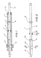
- Figure 1 shows one type of variable ratio rack and pinion steering gear which benefits from the manufacturing method and apparatus according to the present invention.
- Rack bar 1 longitudinally slides in steering gear housing 2 on journals 3 and 4, and on rack support pad 5.
- Housing 2 is also provided with journals for mounting pinion 6, generally at an angle other than at a right angle to the longitudinal axis of rack bar 1, and pinion 6 is generally of an involute helicoidal form.
- Housing 2 also incorporates power cylinder 7 in which slides piston 8 securely fixed to rack bar 1. Journals 3 and 4 incorporate seals as does piston 8 so that oil under pressure supplied to one or other end of cylinder 7 provides assist to the driver's effort according to well known power steering art.
- Figure 2 shows a typical rack bar as would be installed in the steering gear of Figure 1, and comprises toothed end 9 and shank end 10 the latter to which is attached piston 8. It will be seen that the teeth are closely spaced in the on-centre region 100 of the rack bar, and smoothly transform to more widely spaces teeth each side thereof towards full-lock regions 101 and 102.
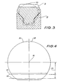
- toothed end 9 has a cross-sectional shape illustrated in Figure 3 (Section III-III of Figure 2), termed for convenience a Y section in accordance with the teaching of US Patent 4,116,085.
- Figure 3 Section III-III of Figure 2
- a rack bar when journalled in the "V" shaped sliding faces incorporated in rack support pad 5, is substantially free from any rolling tendency about its longitudinal axis caused by meshing contact forces between the teeth of pinion 6 and those of rack 1, for reasons stated in the aforementioned patent.
- toothed end 9 has a larger cross-sectional envelope than shank end 10.
- journal 4 incorporating seal 4a must be assembled on to shank end 10 prior to the attachment and retention (for example by circlips) of piston 8 and prior to assembly in housing 2.
- Housing 2 is provided with internal abutment 11 into which is pressed the stepped annulus 4b of journal 4 during steering assembly.
- a D section rack bar may be preferred over a Y section rack bar for reasons of cost saving.
- the present invention describes a means whereby the four primary forming elements as described in US Patent 4,571,982 and International Patent Application No PCT/AU94/00775 are replaced by a pair of opposing die blocks, and the rack shape will be a D section as shown in Figure 4. Side 12 of the toothed end of the rack bar opposing the teeth will now, when finish ground, match that of shank end 10. Note that the rolling moments are largely affected by the distance 13 between the rack bar longitudinal axis 16 and the meshing pitch plane of the rack and pinion teeth, shown as plane 14 for full-lock regions 101 and 102, and plane 15 for on-centre region 100.
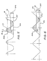
- Figures 5 and 6 show the typical forms of teeth viewed in the transverse planes, that is planes normal to the local skew angle of the teeth, as at regions 100 and 101 respectively of Figure 2. Teeth of the forms shown may be used where the steering ratio selected for the mid turn or cornering region of the vehicle wheels is selected to be of the order of 60-70% of that of the on-centre or straight ahead position of the wheels.
- the pressures achieved during forming of the rack bar teeth largely determine the degree of fill of die toothed recess 26 as indicated by the meniscus radii 17, which is generally most difficult to achieve in the on-centre region ( Figure 5) where the transverse pressure angle 18 is small.
- mean height plane 19 in Figure 5 is considerably closer to plane 204 of the bottom of the teeth (indicated as height 205) than in the case of the corresponding planes of the high pressure angle teeth as shown in Figure 6 (distance between planes 20 and 206 indicated as height 207).
- the total die cavity volume per unit length must take into account these varying tooth volumes if the degree of fill achieved on the rack bar is to be maintained constant along its length. Considerations must also be given to the inevitable variations of stiffness of the die blocks along their length.
- the forging die which, according to the invention, is suited to the warm forming of D section rack bars relates to the pair of opposing die blocks.
- the remainder of the die can be considered to be substantially as described in International Patent Application PCT/AU94/000775.
- appropriate cavities are provided within the upper and lower bolsters (or die members), numbered 18 and 19 in Figures 3 and 4 of that prior art specification, to accommodate rectangular die blocks 21 and 22 in Figure 7 of the present specification.
- the die blocks jointly define a main cavity 23 and chambers 24 located on each side thereof which, in most cases, will extend substantially over the entire length of the die blocks. Further details of main cavity 23 and chambers 24 are shown in Figure 8.
- each abutment 29 overlaps corresponding juxtaposed abutment 28 thereby jointly defining a "stop means" at the laterally remote end of each chamber 24, which restricts flow of material away from main cavity 23 as the final closed position of die blocks 21 and 22 is approached.
- chambers 24 will be influenced by many factors. For example they must be of sufficient width 50 so that raised abutment 28 can resist the lateral shear stress imposed during the final closing of the die.
- the optimum sectional shape of chambers 24 for a particular design of D section rack bar may be arrived at by trial and error or by the use of computer modelling programs. Such programs may typically have as inputs some or all of the following information.
- the variables used in proportioning the chambers include:
- the chambers 24 and raised abutments 28 of die block 22 are tapered in depth in a direction away from main die cavity 23 such that, immediately before final closure, a portion of blank material within chambers 24 is urged back towards main cavity 23 and away from potential entrapment in clearance zone 54. This urging of blank material back towards main cavity 23 ensures that effective tooth fill is achieved.
- Mean depth 51 of chambers 24 may be varied along the length of one or both chambers in order to compensate for the varying volume mean height of the teeth as discussed previously and other factors such as bulk deformation of the die blocks and bolsters.
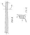
- Figure 9 is a cross sectional view through IX-IX of Figure 8 showing this variation in depth.
- the die may be further simplified by inverting the die elements so that the toothed die block is located in the moving bolster.
- Gripper 24 in the lower bolster 19 ( Figure 5 in International Patent Application No PCT/AU94/00775) may now be fixed and comprises a block having a semi-circular cavity which is precisely an extension of the partly semi-circular recess 27 of die block 21 as shown in Figure 8 of the present specification, but without chambers 24.
- Figure 10 depicts an alternative embodiment, in which chamber 24 and abutments 28 and 29 of die blocks 22 and 21, differ in width to depth ratio to that shown in the earlier embodiment of Figures 7 and 8.
- the shape and size of chamber 24 and abutments 28 and 29 may differ depending on the size and shape of the rack to be forged, the important requirement being that each chamber 24 is fully filled with blank material at final die closure.
Landscapes
- Engineering & Computer Science (AREA)
- Mechanical Engineering (AREA)
- Forging (AREA)
- Warehouses Or Storage Devices (AREA)
- Transmission Devices (AREA)
Claims (5)
- Gesenk zum Formen des gezahnten Endes (9) einer Lenkungszahnstange (1) aus einem zylindrischen Rohling durch Schmieden, wobei das Gesenk erste und zweite Gesenkstücke (21, 22) aufweist, die relativ bewegbar sind, um gegen den Rohling bewegt zu werden, wobei die Gesenkstücke gegenüberliegende, im allgemeinen halbkreisförmige Vertiefungen zum Aufnehmen des Rohlings aufweisen, von denen einer die komplementäre Form der Zähne besitzt, wobei die Vertiefungen zwischen einander einen Haupthohlraum (23) bilden, wenn sich die Gesenkstücke (21, 22) gegeneinander in ihre endgültige geschlossene Stellung bewegen, während subsidiäre Vertiefungen in einem oder beiden Gesenkstücken an der Schnittstelle dazwischen Kammern (24) in der endgültigen geschlossenen Stellung bilden, wobei jede Seite des Haupthohlraums (23) mit einer der Kammern (24) entlang der gesamten Längserstreckung des Haupthohlraums oder zumindest entlang des größten Teils davon mit einer der Kammern (24) kommuniziert, dadurch gekennzeichnet, dass die Kammern (24) im Querschnitt Anschläge aufweisen, die in seitlicher Richtung im Abstand zu dem Haupthohlraum angeordnet sind und den Fluss des Rohlingmaterials von dem Haupthohlraum weg behindern, wobei das Volumen der Kammern (24) in der endgültigen geschlossenen Stellung im wesentlichen gleich wie die Volumensdifferenz zwischen dem Zahnstangenrohling und der fertiggeschmiedeten Lenkzahnstange im Bereich des gezahnten Endes im Haupthohlraum (23) ist.
- Gesenk nach Anspruch 1, wobei das Anschlagmittel in Längsrichtung verlaufende Anschläge (29) an dem ersten Gesenkstück aufweist, die jeweils gegenüberliegende Anschläge (28) an dem zweiten Gesenkstück überlappen, wenn es sich der endgültigen geschlossenen Stellung annähert.
- Gesenk nach Anspruch 1, wobei die Kammern (24) in der Tiefe in Richtung von dem Haupthohlraum (23) weg im allgemeinen hinreichend abgeschrägt sind, um ein weiteres Herausfließen des Rohlingmaterials zu verhindern, wenn es sich der endgültigen geschlossenen Stellung annähert.
- Gesenk nach Anspruch 3, wobei zumindest ein Teil des Rohlingmaterials in den Kammern (24) wieder zurück in Richtung auf den Haupthohlraum (23) gedrückt wird, wenn es sich der endgültigen geschlossenen Stellung annähert.
- Gesenk nach Anspruch 2, wobei jeder der sich in Längsrichtung erstreckenden Anschläge (29) an dem ersten Gesenkstück eine kleine Freiraumzone mit dem jeweils gegenüberliegenden, überlappenden Anschlag (28) an dem zweiten Gesenkstück bildet.
Applications Claiming Priority (4)
| Application Number | Priority Date | Filing Date | Title |
|---|---|---|---|
| AUPN957294 | 1995-12-21 | ||
| AUPN729495 | 1995-12-21 | ||
| AUPN7294A AUPN729495A0 (en) | 1995-12-21 | 1995-12-21 | Method and apparatus for manufacturing steering rack bar |
| PCT/AU1996/000823 WO1997023316A1 (en) | 1995-12-21 | 1996-12-19 | Means to manufacture steering rack bars |
Publications (3)
| Publication Number | Publication Date |
|---|---|
| EP1007243A1 EP1007243A1 (de) | 2000-06-14 |
| EP1007243A4 EP1007243A4 (de) | 2002-01-02 |
| EP1007243B1 true EP1007243B1 (de) | 2004-03-24 |
Family
ID=3791613
Family Applications (1)
| Application Number | Title | Priority Date | Filing Date |
|---|---|---|---|
| EP96941533A Expired - Lifetime EP1007243B1 (de) | 1995-12-21 | 1996-12-19 | Verfahren zur herstellung von lenkzahnstangen |
Country Status (7)
| Country | Link |
|---|---|
| US (1) | US5992205A (de) |
| EP (1) | EP1007243B1 (de) |
| JP (1) | JP2000501996A (de) |
| AU (2) | AUPN729495A0 (de) |
| DE (1) | DE69631977T2 (de) |
| ES (1) | ES2219702T3 (de) |
| WO (1) | WO1997023316A1 (de) |
Cited By (2)
| Publication number | Priority date | Publication date | Assignee | Title |
|---|---|---|---|---|
| CN102198485A (zh) * | 2011-04-20 | 2011-09-28 | 大连大高阀门有限公司 | 铁路机车用240钢锭锻造模具及工艺 |
| DE102010036609A1 (de) | 2010-07-26 | 2012-01-26 | Thyssenkrupp Presta Ag | Gesenk zum Schmieden eines eine Verzahnung aufweisenden Abschnitts einer Zahnstange einer Lenkvorrichtung |
Families Citing this family (6)
| Publication number | Priority date | Publication date | Assignee | Title |
|---|---|---|---|---|
| DE60139361D1 (de) * | 2000-03-09 | 2009-09-10 | Nsk Ltd | Herstellungsverfahren einer hohlen Zahnstange |
| KR100815463B1 (ko) * | 2003-12-04 | 2008-03-20 | 비숍 이노베이션 리미티드 | 스티어링 랙 제조 |
| DE102015100756A1 (de) | 2015-01-20 | 2016-07-21 | FAUDI Aviation GmbH | Mittel zur Vermeidung und/oder Vernichtung von mikrobiellem Bewuchs in einem Lager für einen flüssigen Kohlenwasserstoff, Verfahren zur Vermeidung und/oder Vernichtung von mikrobiellem Bewuchs in einem Lager für einen flüssigen Kohlenwasserstoff, Lager für einen flüssigen Kohlenwasserstoff |
| JP2016179475A (ja) * | 2015-03-23 | 2016-10-13 | 高周波熱錬株式会社 | ラックバー及びラックバーの製造方法 |
| JP2020192681A (ja) * | 2020-08-14 | 2020-12-03 | 高周波熱錬株式会社 | ラックバーの製造方法 |
| CN115366360B (zh) * | 2022-10-26 | 2023-01-10 | 吉林省英华恒瑞生物科技有限公司 | 一种医用试剂盒的生产设备 |
Family Cites Families (15)
| Publication number | Priority date | Publication date | Assignee | Title |
|---|---|---|---|---|
| GB260028A (de) * | 1900-01-01 | |||
| GB556354A (en) * | 1942-03-10 | 1943-09-30 | Herbert Foster | Improvements in or relating to the production of dies for drop forgings |
| GB1015484A (en) * | 1961-12-09 | 1965-12-31 | Gunter Peddinghaus | Method for the production of drop forgings and a die for use therein |
| US3314278A (en) * | 1964-03-03 | 1967-04-18 | Daniel T Bergman | Forging process and product therefrom |
| US3842646A (en) * | 1973-04-20 | 1974-10-22 | Gleason Works | Process and apparatus for densifying powder metal compact to form a gear having a hub portion,and preferred powder metal compact shape for use therewith |
| GB2088256B (en) * | 1980-12-03 | 1984-04-11 | Jidosha Kiki Co | Manufacturing toothed racks |
| JPS5813431A (ja) * | 1981-07-13 | 1983-01-25 | Jidosha Kiki Co Ltd | ラツク製造方法 |
| GB2108026B (en) * | 1981-10-29 | 1985-05-22 | Cam Gears Ltd | Manufacturing a rack member |
| JPS59223132A (ja) * | 1983-06-02 | 1984-12-14 | Honda Motor Co Ltd | 熱間鍛造装置 |
| JPS6027440A (ja) * | 1983-07-26 | 1985-02-12 | Honda Motor Co Ltd | クランクシヤフトの鍛造方法および荒鍛造用金型 |
| DE3542672A1 (de) * | 1984-12-13 | 1986-06-19 | Zahnradfabrik Friedrichshafen Ag, 7990 Friedrichshafen | Pressvorrichtung zur herstellung einer zahnstange |
| SU1595617A1 (ru) * | 1988-06-23 | 1990-09-30 | Предприятие П/Я В-8457 | Способ изготовлени поковок |
| RU1819728C (ru) * | 1991-03-25 | 1993-06-07 | Краматорский Индустриальный Институт | Способ получени изделий с дном и замкнутыми по периметру стенками |
| SE501400C2 (sv) * | 1992-12-30 | 1995-02-06 | Volvo Ab | Sätt att framställa vevstakar |
| AUPM302693A0 (en) * | 1993-12-16 | 1994-01-20 | A.E. Bishop & Associates Pty Limited | Apparatus for manufacturing steering rack bars |
-
1995
- 1995-12-21 AU AUPN7294A patent/AUPN729495A0/en not_active Abandoned
-
1996
- 1996-12-12 US US09/091,407 patent/US5992205A/en not_active Expired - Fee Related
- 1996-12-19 EP EP96941533A patent/EP1007243B1/de not_active Expired - Lifetime
- 1996-12-19 JP JP09523153A patent/JP2000501996A/ja not_active Ceased
- 1996-12-19 AU AU10887/97A patent/AU701524B2/en not_active Ceased
- 1996-12-19 ES ES96941533T patent/ES2219702T3/es not_active Expired - Lifetime
- 1996-12-19 WO PCT/AU1996/000823 patent/WO1997023316A1/en not_active Ceased
- 1996-12-19 DE DE69631977T patent/DE69631977T2/de not_active Expired - Fee Related
Cited By (7)
| Publication number | Priority date | Publication date | Assignee | Title |
|---|---|---|---|---|
| DE102010036609A1 (de) | 2010-07-26 | 2012-01-26 | Thyssenkrupp Presta Ag | Gesenk zum Schmieden eines eine Verzahnung aufweisenden Abschnitts einer Zahnstange einer Lenkvorrichtung |
| WO2012013284A1 (de) | 2010-07-26 | 2012-02-02 | Thyssenkrupp Presta Aktiengesellschaft | Gesenk zum schmieden |
| CN103025453A (zh) * | 2010-07-26 | 2013-04-03 | 蒂森克虏伯普利斯坦有限公司 | 用于锻造的模具 |
| CN103025453B (zh) * | 2010-07-26 | 2015-05-20 | 蒂森克虏伯普利斯坦有限公司 | 用于锻造的模具 |
| US9149860B2 (en) | 2010-07-26 | 2015-10-06 | Thyssenkrupp Presta Aktiengesellschaft | Die for forging |
| DE102010036609B4 (de) * | 2010-07-26 | 2016-08-11 | Thyssenkrupp Presta Aktiengesellschaft | Gesenk zum Schmieden eines eine Verzahnung aufweisenden Abschnitts einer Zahnstange einer Lenkvorrichtung |
| CN102198485A (zh) * | 2011-04-20 | 2011-09-28 | 大连大高阀门有限公司 | 铁路机车用240钢锭锻造模具及工艺 |
Also Published As
| Publication number | Publication date |
|---|---|
| WO1997023316A1 (en) | 1997-07-03 |
| AUPN729495A0 (en) | 1996-01-18 |
| AU1088797A (en) | 1997-07-17 |
| EP1007243A4 (de) | 2002-01-02 |
| AU701524B2 (en) | 1999-01-28 |
| DE69631977D1 (de) | 2004-04-29 |
| JP2000501996A (ja) | 2000-02-22 |
| DE69631977T2 (de) | 2005-03-10 |
| ES2219702T3 (es) | 2004-12-01 |
| EP1007243A1 (de) | 2000-06-14 |
| US5992205A (en) | 1999-11-30 |
Similar Documents
| Publication | Publication Date | Title |
|---|---|---|
| US4715210A (en) | Method for making steering rack bars | |
| EP1694453B1 (de) | Vorrichtung und verfahren zur herstellung von lenkungszahnstangen | |
| EP1007243B1 (de) | Verfahren zur herstellung von lenkzahnstangen | |
| US9149860B2 (en) | Die for forging | |
| US4624283A (en) | Rotary control valve of power steering system and method of producing spool valve member | |
| US6826945B1 (en) | Method for producing a rack | |
| US20070125148A1 (en) | Method and apparatus for forging gear teeth | |
| Groche et al. | Application and modelling of flow forming manufacturing processes for internally geared wheels | |
| EP1576290B1 (de) | Zahnradmaschine mit axialen seitenplatten | |
| Choi et al. | A study on the forging of external spur gears: upper-bound analyses and experiments | |
| Choi et al. | A new extrusion process for helical-gears: experimental study | |
| AU5853899A (en) | Method for producing a gear rack, and a stamping device for carrying out the method | |
| EP1890926B1 (de) | Zahnstangenlenkung mit unterschiedlichen wandstärken | |
| GB2108026A (en) | Manufacturing a rack member | |
| EP1813363A1 (de) | Hydroformpresse zur Herstellung von Formteilen durch Innenhochdruckumformung | |
| US5711395A (en) | Rotary slide valve for power-assisted steering mechanisms of motor vehicles | |
| GB2061138A (en) | Manufacture of rack member for rack and pinion assembly | |
| GB2056894A (en) | Manufacture of rack member for rack and pinion assembly | |
| KR100205257B1 (ko) | 조타장치의 섹터기어 및 그 제조방법 | |
| DE4343841C3 (de) | Verfahren zum Herstellen eines Achslenkers | |
| DE4437398C2 (de) | Antriebswelle und Verfahren zu ihrer Herstellung | |
| Jang et al. | The process sequence design of a power-assisted steering part | |
| WO1983004197A1 (en) | Method and apparatus for making steering rack bars | |
| Osman et al. | Preform design for forging rotationally symmetric parts | |
| AT412395B (de) | Mehrachsiges schwer-nutzfahrzeug |
Legal Events
| Date | Code | Title | Description |
|---|---|---|---|
| PUAI | Public reference made under article 153(3) epc to a published international application that has entered the european phase |
Free format text: ORIGINAL CODE: 0009012 |
|
| 17P | Request for examination filed |
Effective date: 19980715 |
|
| AK | Designated contracting states |
Kind code of ref document: A1 Designated state(s): DE ES FR GB IT SE |
|
| A4 | Supplementary search report drawn up and despatched |
Effective date: 20011120 |
|
| AK | Designated contracting states |
Kind code of ref document: A4 Designated state(s): DE ES FR GB IT SE |
|
| RIC1 | Information provided on ipc code assigned before grant |
Free format text: 7B 21K 1/76 A, 7B 21K 7/12 B, 7B 21J 5/02 B |
|
| GRAP | Despatch of communication of intention to grant a patent |
Free format text: ORIGINAL CODE: EPIDOSNIGR1 |
|
| RAP1 | Party data changed (applicant data changed or rights of an application transferred) |
Owner name: BISHOP STEERING TECHNOLOGY LIMITED |
|
| GRAS | Grant fee paid |
Free format text: ORIGINAL CODE: EPIDOSNIGR3 |
|
| GRAA | (expected) grant |
Free format text: ORIGINAL CODE: 0009210 |
|
| AK | Designated contracting states |
Kind code of ref document: B1 Designated state(s): DE ES FR GB IT SE |
|
| REG | Reference to a national code |
Ref country code: GB Ref legal event code: FG4D |
|
| REG | Reference to a national code |
Ref country code: SE Ref legal event code: TRGR |
|
| REF | Corresponds to: |
Ref document number: 69631977 Country of ref document: DE Date of ref document: 20040429 Kind code of ref document: P |
|
| ET | Fr: translation filed | ||
| REG | Reference to a national code |
Ref country code: ES Ref legal event code: FG2A Ref document number: 2219702 Country of ref document: ES Kind code of ref document: T3 |
|
| PLBE | No opposition filed within time limit |
Free format text: ORIGINAL CODE: 0009261 |
|
| STAA | Information on the status of an ep patent application or granted ep patent |
Free format text: STATUS: NO OPPOSITION FILED WITHIN TIME LIMIT |
|
| 26N | No opposition filed |
Effective date: 20041228 |
|
| PGFP | Annual fee paid to national office [announced via postgrant information from national office to epo] |
Ref country code: SE Payment date: 20050928 Year of fee payment: 10 |
|
| PGFP | Annual fee paid to national office [announced via postgrant information from national office to epo] |
Ref country code: FR Payment date: 20051123 Year of fee payment: 10 |
|
| PGFP | Annual fee paid to national office [announced via postgrant information from national office to epo] |
Ref country code: GB Payment date: 20051124 Year of fee payment: 10 |
|
| PGFP | Annual fee paid to national office [announced via postgrant information from national office to epo] |
Ref country code: ES Payment date: 20051201 Year of fee payment: 10 |
|
| PGFP | Annual fee paid to national office [announced via postgrant information from national office to epo] |
Ref country code: DE Payment date: 20051202 Year of fee payment: 10 |
|
| PG25 | Lapsed in a contracting state [announced via postgrant information from national office to epo] |
Ref country code: SE Free format text: LAPSE BECAUSE OF NON-PAYMENT OF DUE FEES Effective date: 20061220 |
|
| PGFP | Annual fee paid to national office [announced via postgrant information from national office to epo] |
Ref country code: IT Payment date: 20061231 Year of fee payment: 11 |
|
| PG25 | Lapsed in a contracting state [announced via postgrant information from national office to epo] |
Ref country code: DE Free format text: LAPSE BECAUSE OF NON-PAYMENT OF DUE FEES Effective date: 20070703 |
|
| EUG | Se: european patent has lapsed | ||
| GBPC | Gb: european patent ceased through non-payment of renewal fee |
Effective date: 20061219 |
|
| REG | Reference to a national code |
Ref country code: FR Ref legal event code: ST Effective date: 20070831 |
|
| PG25 | Lapsed in a contracting state [announced via postgrant information from national office to epo] |
Ref country code: GB Free format text: LAPSE BECAUSE OF NON-PAYMENT OF DUE FEES Effective date: 20061219 |
|
| REG | Reference to a national code |
Ref country code: ES Ref legal event code: FD2A Effective date: 20061220 |
|
| PG25 | Lapsed in a contracting state [announced via postgrant information from national office to epo] |
Ref country code: FR Free format text: LAPSE BECAUSE OF NON-PAYMENT OF DUE FEES Effective date: 20070102 Ref country code: ES Free format text: LAPSE BECAUSE OF NON-PAYMENT OF DUE FEES Effective date: 20061220 |
|
| PG25 | Lapsed in a contracting state [announced via postgrant information from national office to epo] |
Ref country code: IT Free format text: LAPSE BECAUSE OF NON-PAYMENT OF DUE FEES Effective date: 20071219 |