EP1006560B1 - Durchführung für eine Hochdruckentladungslampe, Beleuchtungssystem mit Spannungsversorgung für eine solche Lampe - Google Patents
Durchführung für eine Hochdruckentladungslampe, Beleuchtungssystem mit Spannungsversorgung für eine solche Lampe Download PDFInfo
- Publication number
- EP1006560B1 EP1006560B1 EP99309768A EP99309768A EP1006560B1 EP 1006560 B1 EP1006560 B1 EP 1006560B1 EP 99309768 A EP99309768 A EP 99309768A EP 99309768 A EP99309768 A EP 99309768A EP 1006560 B1 EP1006560 B1 EP 1006560B1
- Authority
- EP
- European Patent Office
- Prior art keywords
- discharge lamp
- intensity discharge
- reflector
- light
- sealable
- Prior art date
- Legal status (The legal status is an assumption and is not a legal conclusion. Google has not performed a legal analysis and makes no representation as to the accuracy of the status listed.)
- Expired - Lifetime
Links
Images


Classifications
-
- H—ELECTRICITY
- H05—ELECTRIC TECHNIQUES NOT OTHERWISE PROVIDED FOR
- H05B—ELECTRIC HEATING; ELECTRIC LIGHT SOURCES NOT OTHERWISE PROVIDED FOR; CIRCUIT ARRANGEMENTS FOR ELECTRIC LIGHT SOURCES, IN GENERAL
- H05B41/00—Circuit arrangements or apparatus for igniting or operating discharge lamps
- H05B41/14—Circuit arrangements
- H05B41/26—Circuit arrangements in which the lamp is fed by power derived from dc by means of a converter, e.g. by high-voltage dc
- H05B41/28—Circuit arrangements in which the lamp is fed by power derived from dc by means of a converter, e.g. by high-voltage dc using static converters
- H05B41/282—Circuit arrangements in which the lamp is fed by power derived from dc by means of a converter, e.g. by high-voltage dc using static converters with semiconductor devices
-
- H—ELECTRICITY
- H01—ELECTRIC ELEMENTS
- H01J—ELECTRIC DISCHARGE TUBES OR DISCHARGE LAMPS
- H01J61/00—Gas-discharge or vapour-discharge lamps
- H01J61/02—Details
- H01J61/36—Seals between parts of vessels; Seals for leading-in conductors; Leading-in conductors
- H01J61/366—Seals for leading-in conductors
-
- Y—GENERAL TAGGING OF NEW TECHNOLOGICAL DEVELOPMENTS; GENERAL TAGGING OF CROSS-SECTIONAL TECHNOLOGIES SPANNING OVER SEVERAL SECTIONS OF THE IPC; TECHNICAL SUBJECTS COVERED BY FORMER USPC CROSS-REFERENCE ART COLLECTIONS [XRACs] AND DIGESTS
- Y02—TECHNOLOGIES OR APPLICATIONS FOR MITIGATION OR ADAPTATION AGAINST CLIMATE CHANGE
- Y02B—CLIMATE CHANGE MITIGATION TECHNOLOGIES RELATED TO BUILDINGS, e.g. HOUSING, HOUSE APPLIANCES OR RELATED END-USER APPLICATIONS
- Y02B20/00—Energy efficient lighting technologies, e.g. halogen lamps or gas discharge lamps
Definitions
- the present invention relates to a high-intensity discharge lamp which is provided with a discharge lamp enclosure made of light-transmissive ceramics, a high-intensity discharge lamp utilizing the high-intensity discharge lamp, a lighting circuit for the high-intensity discharge lamp, and a lighting device.
- FIG. 30 is a partial enlarged front section showing a sealing portion of a high-discharge lamp provided with a conventional light-transmissive ceramic enclosure.
- FIG. 31 is another partial enlarged front section showing a sealing portion of a conventional high-discharge lamp.
- the numeral 101 denotes a small diameter cylinder portion. Also, the numeral 102 denotes a feed-conductor, and the numeral 103 denotes a sealant.
- the small diameter cylinder portion 101 is coupled to one end of an envelope (not shown) defined in the center of a discharge lamp light-transmissive ceramic enclosure. While the small diameter cylinder portions 101 is defined a through-holes lOla which communicates to the envelope.
- the feed-conductor 102 is provided with a sealable portion 102a and a refractory portion 102b.
- the sealable portion 102a is comprised of a sealable portion 102a 1 which may be inserted in the small diameter cylinder portion 101, and an outer protrusion 102a2 having a tip end to be coupled to the base end of the sealable portion 102a1 and a base end protruding outside the small diameter cylinder portion 101.
- the base end of the refractory portion 102b is coupled to the tip end of the sealable portion 102a made of the sealable metal. Further an electrode is mounted on the tip end of the refractory portion 102b (not shown).
- steps 102a3 and 102b1 are placed on, e.g.,, the tip end of the sealable portion 102a and the base end of the refractory portion 102b at their positions to be welded each other.
- the steps 102a3 and 102b1 are superimposed and then spot-welded each other up and down.
- the feed-conductor 102 is inserted into the small diameter cylinder portion 101. Then a compound of a sealant 103 for sealing ceramics flows into the narrow gap between the small diameter cylinder portion 101 and a sealing portion 10a1 of the sealable portion 102a of the feed-conductor 102 inserted in the small diameter cylinder portion 101 and then solidified so that the small diameter cylinder portion 101 is sealed and the feed-conductor 102 is fixed to a predetermined position.
- the outer protrusion 102a2 of the sealable portion 102a of the feed-conductor 102 protrudes outside and its tip end is coupled to the base end of the sealable portion 102a1.
- the outer protrusion 102a may protrude outside the discharge lamp light-transmissive ceramic enclosure 101and effect as an external lead-wire.
- the outer protrusion 102a must be sealed hermetically by the sealant so as not to be exposed in air for preventing from oxidation.
- the outer protrusion 102a2 is coupled to an external lead-wire (now shown) made of an oxidation-resistant metal, and the junction is fit around by the ceramic washer (not shown), and sealed by a sealant with a melting point lower than that of the sealant 103.
- steps 102a4 and 102a5 defined in the sealable portion 102a1 and the outer protrusion 102a2 are superimposed each other and then spot-welded.
- the inventors have developed a new high-intensity discharge lamp in which the sealable portion of the feed-conductor is formed by rounding a plate in a cylindrical shape with a junction line and filed the invention (hereinafter referred to prior invention) in Japan (Japanese Patent Application 10-257807). Accordingly the sealable portion becomes easy to be coupled to a refractory portion whose tip end being provided with an electrode. The sealable portion then becomes hard to be off-centered from the refractory portion.
- FIG. 32 is a partial enlarged front section showing the prior invention of the high-intensity discharge lamp.
- FIG. 32 the same elements as those shown in FIG. 31 are assigned with same marks.
- the sealable portion 102a of the feed-conductor 102 is comprised of a cylindrical sealable portion 102a1' and an outer protrusion 102a2.
- the cylindrical sealable portion 102a1' is formed by cylindrically rounding a sealable metal plate.
- the cylindrical sealable portion 102a1' has an axially extending junction line j which presents a narrow gap of about 1 to 10 ⁇ m in average.
- the outer protrusion 102a2 is inserted into the cylindrical sealable portion 102a1'. They are thus possible to be coupled each other by a shrinkage fitting at the sealing operation.
- the refractory portion 102b is inserted into the cylindrical sealable portion 102a1', and then coupled thereto by a shrinkage fitting in the same way as that of the outer protrusion 102a2.
- the conventional arts have some drawbacks at the junction of the sealable portion and the refractory portion in the feed-conductor, and at the junction of a sealing and the outer protrusion in the sealable portion. That is, there are problems of that such a spot welding is troublesome and that those thus spot-welded are easy to be off-centered from each other.
- the prior-art high-intensity discharge lamp is favorable in that it is easy to couple the sealable portion and the refractory portion and they are hardly off-centered from each other.
- the sealant fails to enter inside the cylindrical sealable portion 102a1', if it leaks of the sealant occur at both the junction of the refractory portion and the cylindrical sealable portion 102a1' and the junction of the cylindrical sealable portion 102a1' and the outer protrusion 102a2
- the discharge lamp light-transmissive ceramic enclosure 101 looses a hermeticity.
- such a problem could be solved in easy according to the present invention.
- the present invention has an object to provide an enhanced high-intensity discharge lamp, an enhanced high-intensity discharge lamp device, an enhanced high-intensity discharge lamp lighting circuit, and an enhanced lighting device using the lamp, in which feed-conductors fail to be off-centred from the refractory portions, and/or that they present high-reliability of sealing between the discharge lamp light-transmissive ceramic enclosure and the feed-conductor.
- the present invention has another object to provide a high-intensity discharge lamp device in which the high-intensity discharge lamp would not be reduced its life-expectancy even if a shallow reflector is utilized.
- the present invention has still another object to provide a compact high-intensity discharge lamp lighting circuit and a lighting system using the discharge lamp lighting circuit which is able to be miniaturized by using the stabilizer capable of starting the lighting operation by its load characteristics similar to that of a fluorescent lamp stabilizer, and which presents a relatively low blackening level, ie. blackening due to an evaporation of an electrode material at a glow-arc transition.
- a high-intensity discharge lamp characterized by that it is provided with: a discharge lamp light-transmissive ceramic enclosure having an envelope defining a discharge space and a small-diameter cylinder portion communicating with the envelope and having a diameter smaller than the envelope; a feed-conductor, which is comprised of a sealable portion including a coil portion, and a refractory portion having a base end thereof inserted into the coil portion thereby coupling the refractory portion to the coil portion, the feed-conductor extending into the small-diameter cylinder portion of the discharge lamp light-transmissive ceramic enclosure, thereby defining a narrow gap between the refractory portion and the inner surface of the small-diameter cylinder portion; an electrode mounted on the end of the refractory portion of the feed conductor; a sealant for sealing gaps between the smaller-diameter cylinder portion of the discharge lamp light-transmissive ceramic enclosure and the sealable portion of the feed-conduct
- discharge lamp light-transmissive ceramic enclosure means a hermetic discharge lamp enclosure comprised of a monocrystalline metal oxide, eg. a saphire, a polycrystalline metal oxide, eg. a semi-transparent aluminium oxide, an yttrium-aluminium garnet (YAG), AN yttrium oxide (YOX) and a polycrystalline nonoxidic material, e.g., a material having a light-transmissivity and a heat-resistancy like an aluminum nitride (AIN).
- light-transmissivity means a transmissivity allowing a light generated by a discharge to pass through outside a discharge lamp enclosure. Accordingly the term may represent either a transparency or a light-diffusiveness.
- the discharge lamp light-transmissive ceramic enclosure holds thereto an envelope defining a discharge space and an electrode, and a small diameter cylinder portion having a narrow gap for sealing the discharge lamp light-transmissive ceramic enclosure together with a feed-conductor.
- the discharge lamp light-transmissive ceramic enclosure could be formed into a double closed-ends structure with a pair of small diameter cylinder portions coupled to both the ends of the envelope or a single closed-end structure with a small diameter cylinder portion coupled to one end of the envelope.
- a pair of small diameter cylinders may be coupled to both ends of a centrally-located envelope, so as to integrate them together from the outset. Further, it is also able to form an integrated discharge vessel by, e.g., preparing a cylinder forming an envelope, and provisionally sintering individuals of a pair of end plates to be fit to both ends of the cylinder to close the cylinder and a pair of small diameter cylinders to be fit into central holes defined in the end plates to work as the small diameter cylinder portions, and then sintering whole of them after fitting the small diameter cylinders to both end of the former cylinder.
- the interior volume of the discharge lamp light-transmissive ceramic enclosure is particularly effective at a small volume of less than 0.05 cc, or preferably less than 0.04 cc. But it is not necessarily limited to the specific volume.
- Such a compact discharge lamp light-transmissive ceramic enclosure is able to be made in length less than 30 mm, or preferable less than 25 mm. Further it is preferable to set the lamp to have a rated power consumption less than 20 W.
- the feed-conductor is used to at least one of the small diameter cylinder portions of the discharge lamp light-transmissive ceramic enclosure.
- the "feed-conductor” works for applying a voltage across the electrodes via a stabilizer from a power supply, and for starting the high-voltage discharge lamp to operate, and for lighting the discharge lamp by introducing a current thererto.
- the feed-conductor is mounted to the small diameter cylinder portion of the light-transmissive ceramic discharge lamp in sealed hermetically by means as described below.
- the "sealable portion” may be made of a material which is suitable for sealing the discharge lamp light-transmissive ceramic enclosure at a gap between the small diameter cylinder portion and the sealable portion. If needed, further, the sealable portion could be made a material suitable for sealing by interposing a pipe-shaped intermediate ceramic member (so-called as a ceramic pipe) between the small diameter cylinder portion and the sealable portion, e.g., a niobium, a tantalum, a titanium, a zirconium, a hafnium and a vanadium.
- a pipe-shaped intermediate ceramic member e.g., a niobium, a tantalum, a titanium, a zirconium, a hafnium and a vanadium.
- the niobium and the tantalum have almost same average thermal expansion coefficient as that of the aluminum oxide, they are suitable for the sealable portion.
- the niobium and the tantalum have almost same average thermal expansion coefficient as that of the aluminum oxide, they are suitable for the sealable portion.
- the yttrium oxide (YOX) and the yttrium-aluminum garnet (YAG) there is no significant difference in their thermal expansion coefficients.
- the aluminum nitride it is better to use the zirconium as the material of the sealable portion.
- the sealable portion is provided with the coil portion on its tip end. Accordingly, it is possible to couple the sealable portion and the refractory portion together without being off-centered from each other by a shrinkage fitting in a sealing operation, by simply inserting the base end of the refractory portion into the coil portion. If needed, however, they is able to be welded together after inserting the refractory portion into the coil portion. Of course, they are hardly off-centered from each other according to the welding operation.
- the tip end of the sealable metal rod which is inserted in the coil portion of the sealable portion fits in a face-to-face manner to the base end of the refractory portion. Accordingly the coil portion and the refractory portion is able to be combined in more correct straight alignment.
- the entire of or a part of the coil portion of the sealable portion could have a desired coil pitch. For instance, if the coil portion is tight-wound, a sealant described after takes somewhat a time to enter into the interior of the coil portion, but the entire of the feed-conductor could be coupled to the coil portion in a straight alignment.
- the sealant of the ceramic sealing compound is able to enter inter the interior of the coiled principal part of the sealable portion and then form a thick sealing film.
- an outer protrusion made of a sealable metal independently to the coil portion, or to couple an external lead-wire made of a sealable metal directly to the principal part of the sealable portion, instead of using such an independent outer protrusion.
- the independent outer protrusion or a portion of the sealable portion to be coupled to the external lead-wire is able to be constituted by the coil portion. Accordingly, it becomes easy to couple the independent outer protrusion or the external lead-wire to the principal port of the sealable portion without being off-centered from each other.
- the mid-portion of both ends of the coil portion is able to be made of a solid rod or a cylinder made of a sealable metal. In this case, it is able to insert intermediate members into the coil portions on both sides and then couple them together by a shrinkage fitting in the sealing operation or a welding.
- the entire of the sealable portion including the coil portion which will become the tip end of the sealable portion for connecting the refractory portion, the mid-portion for constituting the sealing portion by being inserted the sealant therein, and the independent outer protrusion or the other end to be coupled with the external lead-wire, is constituted by the coil portion.
- the coil portions are able to be formed in integral by coils with the same wire, the same diameter and the same pitch with each other. Or coils different at a part of or whole of the dimensions are individually formed and then coupled together.
- both ends of the coil portion are tight-wound, while its mid-potion will be roughly wound.
- enlarging the coil pitch at the mid-portion the length of the wire of the coil will be reduced.
- the tight-wound coil or the coil with narrow gaps between turns is prepared at first. Both ends of the coil are coupled to predetermined members, and the mid-potion of the coil is stretched to a predetermined length. As a result, a roughly wound coil pitch portion is formed in the mid-portion. However, it is able to use a coil having three sections wound in different pitches from the outset.
- a sealable metal rod in the interior of the coil portion, it is possible to prevent the coil portion from curving undesirably.
- the tip end of the rod fit in a face-to-face manner to the base end of the refractory portion it becomes easy to couple the refractory portion in a straight alignment.
- the rod is able to be used as the outer protrusion.
- the "refractory portion” is a portion comprised of a conductive material which has a high melting point sufficient to resist the high temperature during the operation of the high-intensity discharge lamp.
- the term also indicates a portion of a conductive material which has a corrosion-resistance to an ionizing agent residing in the discharge lamp light-transmissive ceramic enclosure.
- a conductive material which has a corrosion-resistance to an ionizing agent residing in the discharge lamp light-transmissive ceramic enclosure.
- it is able to be made by tungstens, molybdenums, alloys including either of them as a principal element, or platinums.
- it is able to be made by combining above-described several metals, not a single kind of metal alone.
- it may be made a cermet.
- the refractory portion may be a solid rod or a cylinder, i.e., a pipe having a 10 to 300 ⁇ m thickness.
- a solid rod type refractory portion is appropriate to have a diameter less than 0.2 mm.
- a cylinder type refractory portion is appropriate to have a thickness of about 10 to 100 ⁇ m.
- the cylinder type refractory portion may be a cylinder manufactured by cylindrically rounding a thin plate thus leaving a narrow gap junction, as well as a seamless pipe.
- the cylinder type refractory portion is able to absorb a stress caused by a thermal expansion difference between them of the refractory portion and the sealant, even if the thermal expansion coefficient of the sealant is apparently smaller then that of the refractory portion.
- a narrow gap so called a capillary
- a part of the narrow gap at the side of one end of the small diameter cylinder portion is buried by the sealant.
- a rest of the ionizing agent stays in a liquid-phase during the lighting of the lamp.
- the liquid-phase ionizing agent at the side of the discharge space presents a coldest portion. Accordingly, it is able to set desirably the temperatures of the coldest portion and the sealant, by suitably setting the width and the length of the narrow gap and the quantity of the ionizing agent.
- the electrode is mounted on the tip end of the refractory portion of the feed-conductor. Generally the electrode is located inside the envelope of the discharge lamp light-transmissive ceramic enclosure. However, such a requirement of locating the electrode is not essential, but the electrode may be located in the interior of the small diameter cylinder portion. That is, the electrode may be located at a position facing the envelope.
- the electrode could be integrated with the refractory portion of the feed-conductor, other than it had been separated from the refractory portion.
- the tip end of the refractory portion works as the electrode.
- a cathode is able to be integrated with such a refractory portion.
- an anode is constituted as a different piece mounted on the tip end of the refractory portion.
- the electrode is able to be formed by cylindrically rounding a plate made of a tungsten, etc. Accordingly, a surface area of the electrode increases so that the electrode surface current density, which is one of factors determining a ratio of sputtering at the glow discharge mode in the glow-arc transition, decreases. Accordingly, a cathode voltage drop is also decreased, so as to reduce the sputtering. Since the thermal capacity decreases, the glow-arc transition time is shortened. Further, due to an edge effect an electron emission efficiency is enhanced so as to decrease the starting voltage.
- the discharge lamp light-transmissive ceramic enclosure is of a type of one side sealing
- base portions of a pair of electrodes which protrude into the envelope of the discharge lamp light-transmissive ceramic enclosure are able to be covered by an insulating sleeve so as to enhance an electric strength of the space between the base ends of the electrodes.
- the sealant seals the space between the sealable portion of the feed-conductor and the small diameter cylinder portion of the discharge lamp light-transmissive ceramic enclosure by covering the tip end of the sealable portion so as that at least the sealable portion fails to be exposed to the discharge space.
- the sealant is made of a ceramic sealing compound whose melting point is generally higher than 1500 °C, and whose thermal expansion coefficient is close to that of the light-transmissive ceramic, in order to seal the feed-conductor and the discharge lamp light-transmissive ceramic enclosure that will be heated to a high temperature during the lighting operation.
- the ceramic sealing compound which is often called as a frit, is shaped in a ring pellet by forming a pre-blended vitric material. The pellet is then placed on the tip end of the small diameter cylinder portion of the discharge lamp light-transmissive ceramic enclosure and sintered to be melted so as that its solution enters into the narrow gap between the small diameter cylinder portion and the feed-conductor then hardened at the position. As a result, the sealant is formed on a specific position.
- the sealant in order to form the sealant on a predetermined position, first the discharge lamp light-transmissive ceramic enclosure is fixed on a portion to be sealed, then the solid ceramic sealing compound is placed on the tip end to be sealed of the small diameter cylinder portion and then heated. Then, the ceramic sealing compound melts and then enters into the gap between the small diameter cylinder portion and the cylindrical sealable portion. When its solution reaches a predetermined position on the middle of the refractory portion the solution undergoes cooling. Accordingly, the sealant is hardened in order to not only cover the sealable portion for preventing the sealable portion from its exposure to the discharge space of the discharge lamp light-transmissive ceramic enclosure, but also seal the gap between the small diameter cylinder portion and the sealable portion.
- the sealant seals a part of the gap between the small diameter cylinder portion and the refractory portion hermetically. According to the sealant thus formed, the feed-conductor is fixed to a predetermined position, and also the discharge lamp light-transmissive ceramic enclosure is sealed.
- a compact high-intensity discharge lamp it is able to cover the refractory portion of the feed-conductor covered by the sealant across the extent of 0.2 to 0.3 mm in the axial direction If the extent covering the refractory portion is less than 0.2 mm the sealable portion is easily eroded by an ionizing agent such as a halogen. Also, if the extent exceeds 3 mm it is easy to cause a crack on the lamp operation.
- the ionizing agent does not have a limited selection.
- a mercury lamp When using a mercury or rare gases as the ionizing agent, a high-intensity mercury-vapor discharge lamp (so-called a mercury lamp) is able to be achieved.
- a metal halide discharge lamp (so-called a metal halide lamp) is able to be achieved.
- a mercury and a proper pressure of a rare gas are filled in a discharge lamp vessel as a buffer agent.
- the metal halide lamp by filling proper pressures of a neon Ne and an argon Ar in the discharge lamp vessel as buffer gases, the metal halide lamp is able to be favorably lighted in using a high frequency stabilizer which is as compact as the fluorescent lamp stabilizer and a load characteristics smoothly extending from the second-order open-circuit voltage to the second-order short-circuit current, without using an igniter.
- a halogen for constituting the metal halide it is able to use one or a plurality from an iodine I, a bromine Br, a chlorine Cl and a fluorine F.
- the metal halide of a metal for radiating light is able to be selected from a group of known metal halides, in order to achieve a radiation provided with a desired lighting characteristics about a light color, an average color rendering evaluation index Ra and a lighting efficiency, and further in response to the size and the input power of the discharge lamp light-transmissive ceramic enclosure.
- one or a plurality of halides selected among a group of a Na-halide, a Li-halide, an Sc-halide or rare-earth metal-halides could be used.
- a halide of a metal having a relatively high vapor pressure and less radiative or non-radiative visible lights, such as an aluminum Al is able to be filled in the discharge vessel, in place of the mercury.
- a rare gas an argon Ar, a xenon Xe, or a neon Ne could be used.
- the width of the narrow gap between the inner surface of the small diameter cylinder portion and the feed-conductor is not limited in the present invention. However, in case of a relatively compact high-intensity discharge lamp, i.e., discharge lamp light-transmissive ceramic enclosure having an interior volume of less than 0.1 cc, or preferably less than 0.05 cc and/or a rated power consumption less than 20 W it is preferred that the width of the narrow gap is equal to or larger than 0.21 mm.
- the reason is considered that when decreasing the size of the discharge lamp light-transmissive ceramic enclosure, a configuration of thermal conduction from heating elements including a discharge plasma, i.e., a balance of a thermal conduction, a thermal convection and a thermal radiation collapse.
- the average linear transmittance of the envelope is set to 20 % or more, and preferably to 30 % or more.
- the linear transmittance is measured in a wavelength of 550nm.
- the average linear transmittance means an average value of the linear transmittance data measured at different five sampling points.
- the average linear transmittance of its envelope is 20 % or more, it is able to enhance not only the optical efficiency (overall apparatus optical efficiency) including that of an optical system such as a reflector to be combined with the discharge lamp, but also to reduce occurrences of the cracks in the discharge lamp light-transmissive ceramic enclosure.
- the interior volume of the discharge lamp light-transmissive ceramic enclosure is measured in a following way. First, the enclosure is submerged in water to fill the water in the enclosure. Then the enclosure is drawn out from water after the openings of both the small diameter cylinder portions having been closed. Then the volume of the water in the enclosure is metered and measured.
- the overall length of the discharge lamp light-transmissive ceramic enclosure is made less than 30mm.
- the high-intensity discharge lamp could be configured to a type of a lighting bulb being housed in an outer bulb which is evacuated and filled with inert-gas. According to the discharge lamp light-transmissive ceramic enclosure being accommodated in the outer bulb, the temperature of the coldest portion could be easily kept in a desirable high temperature.
- the external lead-wire coupled to the base end of the sealable portion of the feed-conductor and exposing outside the discharge lamp light-transmissive ceramic enclosure may be made of either a metal the same as that of the sealable portion or an oxidation-resistant conductor.
- the outer protrusion could be covered by the second sealant so as not to be exposed outside.
- This configuration is effective for the type of the outer bulb exposing in air.
- the second sealant since the outer protrusion is covered by the second sealant it is possible to prevent to damage or weaken the former sealant (hereinafter the former sealant is referred as the first sealant) for sealing of the discharge lamp light-transmissive ceramic enclosure.
- the sealable portion of the feed-conductor is constituted to have a coil portion at its base end
- the outer protrusion is able to be formed by a sealable metal rod so as that the rod is inserted in the coil portion and then coupled thereto.
- the oxidation-resistive metal could work as the external lead-wire.
- the coil portion when extending the coil portion at the base end of the sealable portion, the coil portion could work as the outer protrusion.
- the extent between the coil portions of the tip end and the base end of the sealing portion is able to be formed integrally by the coil portion. If needed, however, the coil portions of the tip end and the base end of the sealing portion may be communicated via a rod or a pipe.
- the second sealant must be the one whose thermal expansion coefficient is close to that of the sealable portion of the external lead-wire or the feed-conductor, and also whose melting point is substantially lower than that of the first sealant. For instance, since the melting point of the second sealant is lower than that of the first sealant by 300 °C or more, when the second sealant is formed by heating and melting the ceramic sealing compound it is hard to cause the distortion on the first sealant that had been already formed. Accordingly it is also hard to cause the crack on the first sealant.
- the second sealant have the melting point lower than that of the first sealant by 300 °C or more, the melting point of the second sealant is also lower than that of platinum.
- a considerably inexpensive sealable metal is able to be used for the external lead-wire.
- the second sealant have a melting point lower than that of the first sealant by 400 °C or more, it is more hard to cause the distortion on the first sealant. Accordingly the sealing by the second sealant would become easy.
- the following materials would be preferable.
- the second sealant is constituted by an oxide of at least three or more elements selected from a group of Si, B, Pb, Na, Ba, Zn, Ca and Mg, as a principal element, the second sealant is easy to have a low melting point is low and a thermal expansion coefficient close to that of the sealable portion of the feed-conductor. Accordingly, the sealable metal having the lower melting point could be used for the external lead-wire.
- Table 1 lists up materials, compositions, melting points and thermal expansion coefficients of the second sealant. Here, all the materials are available from Nippon Denki Glass Co. Ltd. [Table 1] No. Glass-Cord Composition Melting Point °C Coefficient of Thermal Expansion ⁇ 10 -6 /°C 1 GA- 1 PbO-B2O 3 -SiO2 788 6.0 2 GA- 4 Na2O-B2O2-SiO2 767 6.3 3 GA- 8 PbO-B2O2-SiO2 557 8.1 4 GA- 9 PbO-B2O2-SiO2 - 9.0 5 GA-11 PbO-BaO-SiON2 - 8.8 6 GA-12 Na2O-B2O3-ZnO 687 7.3 7 GA-13 CaO-BaO-SiO2 1045 6.6 8 GA-44 MgO-B2O2-SiO2 850 11.7 9 GA-60 MgO-B2O2-SiO2 850 9.6
- the second sealant would be desirable to have a thermal expansion coefficient from 6 ⁇ 10 -6 /°C to 12 ⁇ 10 -6 /°C, and a melting point lower than 1200 °C.
- the external lead-wire is a sealable alloy containing an Fe and an Ni
- the external lead-wire could have a low melting point, an oxidation-resistance, a conductivity, and a low cost.
- an Fe-Ni-Co alloy, an Fe-Ni-Cr alloy etc. are useful for the external lead-wire. These alloys present a favorable wettability for a solution of the sealant and a thermal expansion coefficient falling in a tolerance.
- sealant also covers to seal the tip end of the external lead-wire coupled to the outer protrusion simultaneously, for covering the protrusion of the sealable portion.
- the outer surface of the portion to be sealed is able to be fit around by the ceramic washer, so as that the second sealant is filled inside the ceramic washer.
- the external lead-wire may be led in the axial direction or the direction orthogonal to the axis of the discharge lamp light-transmissive ceramic enclosure.
- At least one end of the external lead-wire extends to the direction orthogonal to the axis of the discharge lamp light-transmissive ceramic enclosure.
- the external lead-wire is bent in the right angle. In such a case, since the external lead-wire is bent, a dead space is generated in the axial direction of the high-intensity discharge lamp around the bent portion, so as to disturb the minituarization of the lamp device.
- the external lead-wire is able to be coupled to one pair of electrode by making both of the external lead-wires cross the axis of the discharge lamp light-transmissive ceramic enclosure. And also it is able to make only one of t external lead-wires cross the axis of the discharge lamp light-transmissive ceramic enclosure.
- the former configuration is effective for the case that the high-intensity discharge lamp is mounted to on the reflector by orthogonally crossing its axis of the discharge lamp light-transmissive ceramic enclosure with the optical axis of the reflector.
- the latter configuration is effective to the external lead-wire at the side of the light-projecting opening of the reflector in the case of aligning the high-intensity discharge lamp on the reflector by making the axis of the light-transmissive ceramic discharge lamp in co-axial with the optical axis of the reflector.
- the angle for the external lead-wire crossing to the discharge lamp light-transmissive ceramic enclosure is generally 90°. If needed, however, it is allowable to be any desirable angle other than such angle.
- the external lead-wire is able to be coupled to the outer protrusion after the discharge lamp light-transmissive ceramic enclosure is sealed, the coupling operability is enhanced.
- the present invention is not limited to the manufacturing process as mentioned above. Accordingly, the external lead-wire is able to be coupled to the outer protrusion of the feed-conductor beforehand. In such a case, the outer protrusion is able to be covered by the sealant at the same time of sealing the discharge lamp light-transmissive ceramic enclosure.
- the high-intensity discharge lamp which is able to light in air by providing the external lead-wire constituted of the acid-resistive metal.
- the external lead-wire comprised of the acid-resistive metal When the external lead-wire comprised of the acid-resistive metal is coupled to the sealable metal, it is provided with an axial hole formed in the axial direction and a pass-through portion which reaches the outer surface through the axial hole. And also, by using the ceramics washer placed in the proximity of the edge of the small diameter cylinder portion of the light-transmissive ceramics discharge enclosure in the way that the base end of the sealable portion of the feed-conductor is placed in the axial hole, the external lead-wire is inserted in the through-hole of the ceramic washer and coupled to the sealable portion in the axial hole, so as to cross the axis of the discharge lamp light-transmissive ceramic enclosure.
- an alumna ceramic which is shaped in a washer shape and defined a through-hole at its center is able to be used. Then the center hole is fit around the outer protrusion so as to make a barrier for sheathing a running-out of a melted solution of the sealant.
- the outer protrusion is covered by the second sealant by using the ceramic washer
- the ceramic washer is worked to be provided thereto a pass-through portion in a form of a radial slit, a radial groove or a simple through-hole. Then the external lead-wire is passed through the pass-through portion, i.e., the slit, the groove or the through-hole defined on the ceramic washer. Further, there may be a case that the external lead-wire is led out from a gap between a ceramic washer and the end surface of the small diameter cylinder portion of the discharge lamp light-transmissive ceramic enclosure, without working the ceramic washer.
- the high-intensity discharge lamp it is provided with a coil portion on the sealable portion of the feed-conductor, so as to make it easy to couple the refractory portion and resistant to be off-centered from the sealable portion at a coupling operation.
- the sealing film is able to be formed inside the coil portion by the sealant being melted and then entering inside the coil portion, so as to enhance the sealing reliability.
- the coupling portion of the sealable portion may be formed as a coil portion. In such a configuration, it is easy to couple the outer protrusion and the external lead-wire to the sealable portion and becomes hard to be off-centered from each other.
- the high-intensity discharge lamp device comprising;
- the present invention is characterized by that at least the mid-portion of the sealable portion of the feed-conductor is constituted by a coil portion. Accordingly, it is able to easily and surely form a sealing film as thick as possible by entering the sealant inside the sealable portion of the feed-conductor. When the sealing film is formed inside the sealable portion, it is able to enhance the sealing reliability.
- the sealing film is formed between the sealable portion and the coupling portion, even if the crack is caused on one or both of the sealable portion and the coupling portion the sealing is not broken. Accordingly, according to the present invention, it is able to enhance the sealing reliability.
- the present invention since it is easy to form a thick sealing film by the sealant inflating inside the coil portion on the middle of the sealable portion, it is able to further enhance the sealing reliability.
- it may adopt another configuration in which a sealable metal rod is inserted inside the coil portion on the mid-portion, so as to make the sealable portion hard to bend. Further, by fitting in a face-to-face manner the tip end of the rod to the base end of the refractory portion, it is also make the entire of the feed-conductor hard to bend.
- the mid-portion of the sealable portion is able to be formed to be the coil portion. In this case, it is able to make the extent across the mid-portion to the tip end as a continuous coil portion If needed, however, the coil portions of the tip end and the base end of the sealing portion may be communicated via a rod or a pipe. In either case, by forming the tip end into the coil portion, the refractory portion is able to be easily coupled to the sealable portion without being off-centered therefrom.
- such a coil portion may be formed on the base end side of the sealable portion, in addition to the one formed on the mid-portion of the sealable portion.
- it is able to make the extent across the mid-portion to the tip end as a continuous coil portion, also able to link the mid-portion and the tip end by a different member as described above.
- by forming the coil portion at the base end side it is able to easily couple the outer protrusion or the external lead-wire to the coil portion without being off-centered from each other.
- the coil portion can be formed on either side of the tip end and the base end of the sealable portion in addition to the mid-portion, according to the configuration as mentioned above.
- the high-intensity discharge lamp device according to the invention of claim 3, further comprising:
- the axis of the high-intensity discharge lamp is able to be co-axial with the optical axis of the reflector, or may be orthogonal to the optical axis of the reflector.
- the reflector and the high-intensity discharge lamp may be integrated by directly fixing them with a refractory adhesive, or they may be indirectly fixed via a third member.
- the reflector and the high-intensity discharge lamp are able to be fixed to each other so as to have a desirable optical relation with each other.
- the high-intensity discharge lamp may be the type of the outer bulb exposing in air, or the type of the outer bulb being accommodated in the outer bulb.
- the present invention since it is able to use the compact high-intensity discharge lamp having a rated power consumption about 20 W, it is able to obtain the high-intensity discharge lamp device which is totally compact and have an excellent light condensing capability.
- the high-intensity discharge lamp device is characterized by that it is provided with;
- the reflector if it is shaped in concave, may be a rotary second-order curved surface such as a rotary parabolic surface or a rotary oval surface, or their corrected curved surfaces.
- the reflector is able to be configured by forming a reflection surface on a base body made of such a glass or a metal, or shaping a refractive metal, e.g., an aluminum, a silver, a chromium, etc., or an alloy including one of them as a principal element.
- a refractive metal e.g., an aluminum, a silver, a chromium, etc., or an alloy including one of them as a principal element.
- the reflection surface may allow a configuration having the visible radiation reflect/infrared ray transmit capability made of a multi-layered interference film, or a evaporation coating of a reflecting metal.
- the support base is able to be used for defining a position for installing the reflector or for fixing the reflector.
- For fixing the reflector it is able to not only form the supporting base into a cylindrical shape, but also form a protrusion capable of inserting into the cylinder portion of the supporting base on a receiving side and then fix them using a refractory adhesive.
- the feature that "the principal part of the sealant made of ceramic sealing compound substantially fails to be exposed inside” means that a portion effective for sealing fails to be exposed to the reflector surface.
- the surface of the sealant at side of the discharge space and their proximity fail to constitute the principal part, even though they extend to the refractory portion of the feed-conductor for enveloping the entire of the sealable portion.
- the portion presenting a hermetic section in the small diameter cylinder portion configures a a part of the principal part.
- the mid-portion is able to be placed on a portion near to the edge of the reflector, or being exposed outside from the outer surface of the reflector. To this end, it is better to form through-holes on the reflector for passing there-through the small diameter cylinder portions. Further it is able to leave a space between the through-holes and the small diameter cylinder portions. Further, it may configure that the high-intensity discharge lamp is not fixed to the reflector but supported by the external lead-wire.
- the space is filled with a heat-shielding inorganic adhesive, so as to fix the high-intensity discharge lamp and shut out the heat emission.
- the high-intensity discharge lamp may be a configuration that the discharge lamp light-transmissive ceramic enclosure is accommodated in the outer bulb.
- the high-intensity discharge lamp is mounted on the reflector having an optical axis orthogonal to the axis of the discharge lamp light-transmissive ceramic enclosure with the optical axis of the reflector, and the principal part of the ceramic sealing compound substantially fails to be exposed to the inner surface of the reflector.
- the temperature of the sealant rises during the lighting operation of the high-intensity discharge lamp but prevented from an excessive rise. Accordingly the temperature rise of the sealant makes a leak hard to cause.
- the radiant light and the radiant heat of the high-intensity discharge lamp reflect at the inner surface of the reflector, and a part of them radiates the bare part of the sealant, the temperature at the bare part rises.
- the ionizing agent stays in a liquid-phase in the narrow gaps formed inside the small diameter cylinder portions at both ends of the discharge lamp light-transmissive ceramic enclosure, but the surface of the liquid-phase ionizing agent at the side of the discharge space becomes the coldest portion regardless of the lighting position of the high-intensity discharge lamp, then the vapor pressure of the ionizing agent is defined. Accordingly, since the coldest portion presents at a fixed position near the reflector surface of the reflector, the liquid-phase ionizing agent does not disturb the light condensing operation of the reflector.
- the high-intensity discharge lamp having the transparent discharge enclosure made of a silica glass since such a lamp does generally not include such a narrow gap, the coldest portion presents on one part of the bulb wall of the discharge space. Accordingly, if the high-intensity discharge lamp made of the silica glass is placed its one side on the concave reflector so as that the top portion of the reflector condenses the light such as the present invention, it causes a problem that the quality of the light is lowered due to the light being shaded by the liquid-phase ionizing agent at the coldest portion stick to the bulb wall.
- the reflector is able to desirable condense the light even if the reflector is shallow, it is possible to make the high-intensity discharge lamp device compact.
- the top portion and its vicinity of the reflector works effectively to condense the light, the distribution of the light could be sharp, and not be disturbed.
- the high-intensity discharge lamp device according to the invention of claim 5 is characterized by that further to the high-intensity discharge lamp device as claimed in claim 4 the surface of the liquid phase ionizing agent developed during the operation of the high-intensity discharge lamp in the narrow gap between the small diameter cylinder portion of the discharge lamp light-tranamissive ceramic enclosure and the feed-conductor places at a side of the interior of the reflector.
- the temperature of the sealant in the high-intensity discharge lamp provided with the discharge lamp light-transmissive ceramic enclosure, it is possible to confine the temperature of the sealant in a proper tolerance by elongating the small diameter cylinder portion. Further, the coldest portion presents on the surface of the liquid-phase ionizing agent residing in the narrow gap in the small diameter cylinder portion at the side of the discharge space. If the temperature is excessively low, it is unable to obtain a desired lamp efficiency. Accordingly, the temperature of the coldest portion is better as high as possible to obtain the high lamp efficiency.
- the portion of the liquid phase ionizing agent where the coldest portion is presenting looks, as its surface facing the discharge space, toward the inner surface of the reflector, the surface of the liquid-phase ionizing agent is heated by the reflections of the radiant heat and the visible radiation from the high-intensity discharge lamp in the reflector. Accordingly, it is possible to obtain a desirable high lamp efficiency by the temperature of the coldest portion being raised.
- the coldest portion presents at a position near the reflector surface of the reflector, it does not deteriorate the quality of the light distribution remarkable.
- the high-intensity discharge lamp device is characterized that further to the high-intensity discharge lamp device as claimed in claim 4 or 5, the reflector is provided with a pair of through-holes at positions symmetrical in regard to a line vertically crossing the optical axis of the reflector at a focus point of the reflector, and a pair of small diameter cylinder portions of the discharge lamp light-transmissive ceramic enclosure is inserted into the through-holes.
- This invention provides a suitable configuration for mounting the high-intensity discharge lamp on the reflector.
- the through-hole of the reflector and the small diameter cylinder portion may be fixed by filling the heat-shielding inorganic adhesive between the gap of them. If needed, further, the gap may be left in vacant.
- a cooling undergoes by permitting entering of air into the gap.
- the reflector and the high-intensity discharge lamp may be supported separately.
- the reflection surface of the reflector excluding the through-holes is able to be minimized, it is possible to obtain the high-intensity discharge lamp device provided with the reflector having a high reflection efficiency.
- a pair of the small diameter cylinder portions which extend from the centrally located envelope to both sides becomes longer to a certain extent for the sealing principal under any conditions.
- the non-reflection portion is able to be minimized.
- This invention is constructed with the high-intensity discharge lamp and the stabilizer for lighting the lamp. However, by combining them it is possible to obtain a less-expensive and a compact high-intensity discharge lamp lighting circuit.
- the high-intensity discharge lamp in general it is necessary to use a stabilizer wherein an igniter for generating a relatively high pulse voltage at the starting time is integrated.
- the stabilizer of the high-intensity discharge lamp is overwhelmingly large in comparison with that of the fluorescent lamp with the same rated lamp power. Accordingly, even if a compact high-intensity discharge lamp is provided for all troubles, an overall system containing a light source, a stabilizer and a lighting apparatus results to have a large size.
- the inventor has studied to use a stabilizer principally constituted by a compact high-frequency inverter which is used for the fluorescent lamp, especially for the electric bulb fluorescent lamp.
- the stabilizer for the electric bulb shaped fluorescent lamp is generally simple in its circuit arrangement, and works at a high frequency. Accordingly, such a stabilizer is compact, light in weight and less-expensive.
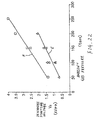
- FIG. 20 is a graph showing the load characteristics of the high-discharge lamp stabilizer and the fluorescent lamp stabilizer.
- the horizontal axis shows a current and the vertical axis shows a voltage.
- the curve A shows the load characteristics of the high-discharge lamp stabilizer
- the curve B shows the one of the fluorescent lamp stabilizer.
- the load characteristics of the high-discharge lamp stabilizer as shown in the characteristic curve A, the second-order open-circuit voltage V20 is relatively low but the second-order short-circuit current IS is relatively high. This is because that a higher pulse voltage is generated by an igniter at the starting operation, then superposed to the output voltage of the stabilizer and lastly the superposed voltage is applied to lamp. So that the stabilizer is not required to generate a too-high voltage at the starting time. Further since the lamp voltage is low at the starting time in the high-intensity discharge lamp the lamp current be enlarged.
- the second-order open-circuit voltage V20 is relatively high but the second-order short circuit current IS is relatively slow. Then, the curve B smoothly extends between these two points. Accordingly, in the lower current region corresponding to the glow-arc transition time, e.g., in the region lower than the 30 mA, the second-order open-circuit voltage is higher than that of the high-intensity discharge lamp stabilizer
- the glow power in the case of using the fluorescent lamp stabilizer was several times higher than that in the case of using the high-intensity discharge lamp stabilizer.
- the ionizing agent contains a neon and an argon as the buffer gas, and the ionizing agent is inserted in the discharge lamp light-transmissive ceramic enclosure so as to present 1 atmospheric pressure or more during the operation of the lamp.
- the argon is mixed with the neon at the ratio of 0.1 - 10 % in the percent pressure.
- the neon and the argon are generally used at an ambient pressure of 50 to 580 torr.
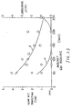
- the ambient pressure is less than 50 torr, the glow-arc transition time becomes longer, and the blackening due to the evaporation of the tungsten constituting electrode becomes significant.
- the ambient pressure exceeds 580 torr, the operating voltage of the high-intensity discharge lamp rises, and the glow power increases, and thus the object of the present invention cannot be achieved.
- the glow-arc transition time and the extent of the blackening vary in accordance with the ambient pressure of the buffer gas. The more the ambient pressure increases, the more the glow power increases, and the more the heating temperature of the electrode rises. As a result, the glow-arc transition time tends to be shortened.
- the glow-arc transition time will be 2 to 3 seconds, and also the blackening is remarkably reduced.
- the glow-arc transition time in such extent resides in a tolerance in practical application.
- the load characteristics of the applicable stabilizer is the same as that represented in the case of the fluorescent lamp stabilizer. Further, the present invention is backed by a new knowledge that even though the high-intensity discharge lamp combined with then above-described constructions by the stabilizer having such load characteristics is operated, the blackening does not occur at that situation.
- the stabilizer for the fluorescent lamp is able to be diverted for the present invention.
- the stabilizer which is manufactured for the high-intensity discharge lamp to satisfy a predetermined load characteristics.
- high frequency means the frequency of 10 kHz or higher.
- the second-order open-circuit voltage V20 of the stabilizer is set up within the range having relatively large flexibility for the discharge starting voltage of the high-intensity discharge lamp. That is, the ratio V20/VS of the second-order opening discharge voltage V20 of the stabilizer to the discharge starting voltage VS of the high-intensity discharge lamp is able to be set up in the following range, 160 ⁇ V 20 / V S ⁇ 300
- the second-order opening voltage of the stabilizer is close to the discharge starting voltage of the high-intensity discharge lamp, and the glow power at the starting operation time is able to be lowered.
- the "second-order open-circuit voltage is close to the discharge starting voltage" means that the second-order voltage V20 is higher by 170 to 200 % than the discharge starting voltage of the high-intensity discharge lamp.
- the stabilizer is preferable to have a load characteristics in that the second-order opening discharge voltage V20 is less than 2.5 kVp-p, more preferably less than 2 kVp-p, and the second-order short-circuit current IS is less than 1.0 A
- the principal circuit arrangement of the stabilizer may be any type if it has the load characteristics as mentioned above.
- the stabilizer may have a circuit arrangement constituted by principally a half bridge inverter, a full-bridge inverter, a parallel inverter, a single-transistor type inverter such as a blocking oscillator inverter.
- the glow-arc discharge is needed to change from a usual glow discharge to an unusual glow discharge.
- a requirement for the glow-arc transition is not only a co-relation between the cathode voltage drop VK and the current density measured on electrode j/p 2 (here, j denotes a glow discharge current (mA), and p denotes an electrode surface area (mm 2 )), but also varies in accordance with the buffer gas.
- the ionizing agent contains a neon and an argon as a buffer gas
- the electrode passes through the small diameter cylinder portion of the discharge lamp light-transmissive ceramic enclosure, and also the stabilizer has a load characteristics the same as that of the fluorescent lamp stabilizer, i.e., a load characteristics smoothly extending from the secondary open-circuit voltage to the second-order short-circuit current the same as the fluorescent lamp stabilizer, it is possible to lower the glow power at the glow-arc transition.
- the buffer gas is comprised of both the neon and the argon
- the glow current at the transition from the usual glow discharge to the unusual glow discharge shrinks. So that the glow power also shrinks.
- the mid-portion of the electrode which is passing through the narrow gap of the small diameter cylinder portion works as an electrode, like the edge portion of the electrode protruding to the envelope of the discharge lamp light-transmissive ceramic enclosure, the effective surface of the electrode increases. Accordingly, even though the cathode voltage drop is fixed, the current density measured on electrode is lowered.
- the buffer gas is comprised of both the neon and the argon
- the discharge starting voltage is lowered as is already known in comparison to the case that only the argon is used as the buffer gas, it is able to lower the voltage which is supplied from the stabilizer at the glow-arc transition, and thus the glow current is lowered.
- the buffer gas is comprised of both the neon and the argon, the positive column loss increases in comparison to the case that only the argon is used as the buffer gas, and thus a voltage to be supplied to electrodes is.
- the glow power is reduced to about 1/5 in comparison to the argon unit. It is found that the glow-arc transition time is extended, the evaporation of the tungsten of the electrode is depressed, and thus the blackening is remarkably reduced. Here the glow-arc transition time is able to be confined in a proper tolerance in practical application by optimizing the ambient pressure of the buffer gas.
- the high-intensity discharge lamp lighting circuit of the invention of claim 8 is characterized in that further to the high-intensity discharge lamp lighting circuit clamed in claim 7 a stabilizer is constituted by principally a high frequency inverter provided with an LC oscillator.
- inverter satisfying the requirements as mentioned above, it is able to be used a half bridge inverter, a single-transistor type inverter, e.g., a blocking oscillator inverter, or a parallel inverter.
- the oscillation control of the inverter may be done by either of a self-excitation or a separate-excitation. Further, the oscillating frequency of the inverter may be made by either fixed or variable.
- the output voltage of the stabilizer is able to be controlled by changing the oscillating frequency of the inverter. That is, if the oscillating frequency is brought closer to the resonance frequency of the LC resonance circuit at the starting operation, the output voltage rises, and thus the second-order open-circuit voltage is able to be brought closer to the discharge starting voltage of the high-intensity discharge lamp.
- the stabilizer with a load characteristics which smoothly extends from the second-order discharge voltage close to the discharge starting voltage of the high-intensity discharge lamp to the second-order short-circuit current.
- the oscillating frequency when it is fixed, it is able to control the output voltage of the stabilizer, by constituting the LC resonance circuit so as that its resonance frequency varies in response to a situation. That is, when it is so arranged that the inductor L of the LC resonance circuit saturates at a nonloaded state, the inductance of the inductor L shrinks under saturation, while the resonance frequency rises, so that the resonance frequency will approach the oscillating frequency. As a result, the output voltage of the stabilizer rises. Further, at a loaded state, the saturation of the inductor L of the LC resonance circuit is released according to the lamp current, and the inductance rises, so that the resonance frequency is estranged and the output voltage is reduced.
- the circuit arrangement is simplified, and thus it is possible to obtain the compact and inexpensive high-intensity discharge lamp lighting.
- the stabilizer is provided with the LC resonance circuit, the waveform of the output voltage is able to be shaped to a sinusoidal waveform.
- the lighting device of the invention of claim 9, comprising:
- the "lighting system” has wide varieties including any devices using a light of the high-intensity discharge lamp in one object or another.
- the lighting system is able to be applied to a light bulb type high-intensity discharge lamp, a lighting equipment, a mobile head light, a light source for optical fibers, an image projection device, an opto-chemical device, or a fingerprint discrimination device.
- the "lighting device principal body” designates a whole portion of the lighting system except the high-intensity discharge lamp.
- the "light bulb type high-intensity discharge lamp” means the lighting system in which the high-intensity discharge lamp and the stabilizer are integrated together, and provided with a bulb-base for receiving a power when connected to a lamp socket, so as to allow to be used in similar manner to the ordinary incandescent lamp.
- the light bulb type high-intensity discharge lamp it is able to provide a reflector for condensing light so as that the high-intensity discharge lamp presents a desired light distribution characteristics.
- the high-intensity discharge lamp is able to provide a light diffusion glove, or a cover in place of or in addition to the reflector.
- a bulb-base having a desirable requirement Accordingly, for replacing directly with conventional light lamps, a bulb-base the same as that of the conventional light lamps is able to be adopted.
- the discharge lamp lighting device for lighting the high-intensity discharge lamp it is preferred to comprise a high frequency lighting circuit having an inverter and a current limiter for reducing in size and weight.
- the current limiter is able to use an inductor, a resistor or a capacitor.
- FIGS. 1 to 29 some embodiments of the present invention will be explained hereinafter.
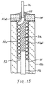
- FIG. 1 is a partial front section of a first embodiment of the high-intensity discharge lamp according to the present invention.
- FIG. 2 is a partial vertical section of the high-intensity discharge lamp in its upper portion being sealed.
- FIG. 3 is a partial enlarged side view showing the upper portion of the high-intensity discharge lamp.
- FIG. 4 is a partial enlarged plan view of the high-intensity discharge lamp in its upper portion being unsealed.
- FIG. 5 is a vertical section of the upper portion of the same high-intensity discharge lamp.
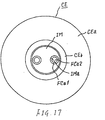
- CE denotes a discharge lamp light-transmissive ceramic enclosure
- FC denotes a feed-conductor
- XL denotes a cross-wire
- OL denotes a external lead-wire
- E denotes an electrode
- S1 denotes a first sealant
- CW denotes a ceramic washer
- S2 denotes a second sealant.
- the discharge lamp light-transmissive ceramic enclosure CE made of YAG, is provided with an envelope CEa and a small diameter cylinder portions CEb, CEb.
- the envelope CEa has a maximum outer diameter of about 5.5 mm.
- the small diameter cylinder portion SEb has an outer diameter of 1.7 mm, a length of 25 mm and an interior volume of about 0.03 cc.
- the envelope CEa is hollow and almost oval whose both ends are shrunk by smooth curved surfaces.
- the small diameter cylinder portion CEb is coupled to the envelope CEa by a smooth curved surface, so as to integrally form the discharge lamp light-transmissive ceramic enclosure CE.
- the feed-conductor FC is comprised of a sealable portion FCa and a refractory portion FCb.
- the sealable portion FCa is comprised of a coil portion FCa1 and an outer protrusion FCa2.
- the coil portion FCa1 is shaped by winding a 0.15 mm thick niobium wire by 10 turns to have a diameter of 0.6 mm, an inner diameter of 0.30 mm and a length 1.7 mm.
- the outer protrusion FCa2 is made of a niobium rod of 0.2 mm diameter and 0.7 mm length. About half length of the outer protrusion FCa2 in its tip end side is inserted in the coil portion FCa1 from its base end and then coupled to the coil portion FCa1 by welding.
- the refractory portion FCb is made of a 0.2 mm thick tungsten rod. Its base end is inserted into the upper portion of the end coil portion FCa1 and then coupled to the sealable portion FCa by welding.
- the feed-conductor FC is inserted into the small diameter cylinder portion CEb in the state that the base end of the outer protrusion FCa2 of protrudes outside the discharge lamp light-transmissive ceramic enclosure CE.
- the feed-conductor FC is then supported to the discharge lamp light-transmissive ceramic enclosure CE by the first sealant S1.
- a narrow gap g is formed between the inner surface of the small diameter cylinder portion CEb of the discharge lamp light-transmissive ceramic enclosure CE and the outer surface of the refractory portion FCb.
- a cross-wire XW is comprised of a niobium thin wire.
- the cross-wire XW is then welded to the outer wall of the outer protrusion portion FCa2 of the sealable portion FCa so as that the cross-wire XW works for positioning the feed-conductor FC to the small diameter cylinder portion CE.
- the cross-wire XW is omitted in FIG. 2.
- the external lead-wire OL is made of a Fe-Ni-Co alloy. Its end is welded to the base end of the outer protrusion FC2 of the sealable portion FCa in an angle of 90 ° .
- the electrode E is shaped in a cylinder by rounding an about 50 ⁇ m thick tungsten plate in leaving a junction line jl with a narrow gap of about 2 ⁇ m so as to have an inner diameter of 0.29 mm and a length of 1.2 mm.
- the electrode E is then coupled the tip end of the refractory portion FCb of the feed-conductor FC by fitting thereto.
- the first sealant S1 is made of a ceramic sealing compound of Al2O3-SiO2-Dy2O3 type, i.e., a frit glass, whose melting point is 1550 °C.
- the first sealant S1 seals the discharge lamp light-transmissive ceramic enclosure CE by entering in the narrow gap formed between the small diameter cylinder portion CEb of the transparent CE and the base ends of the sealable portion FCa and the base end of FCb, and also supports the feed-conductor FC in a predetermined position. Then, the first sealant S1 will make a thick sealing film S1a in the interior of mid-portion of the coil portion FCa1.
- the ceramic washer CW is made of an alumina ceramics, and having an outer diameter the same as that of the small diameter cylinder portion CEb and an axial hole CWa in its center. Furthermore, the ceramic washer CW is formed on its top a groove CWb which communicates the axial hole CWa to outside. The ceramic washer CW is placed on the tip end of the small diameter portion CEb. In the axial hole CWa the base end of the outer protrusion FC2a of the sealable portion FCa and the tip end of the external lead-wire OL coupled to the sealable portion FCa are stored. The external lead-wire OL is also stored in the groove CWb on the ceramic washer CW, and the extends in the right angle in reference to the axis of the transparent ceramic discharge lamp enclosure CE.
- the second sealant S2 is made of an adhesive glass of CaO-BaO-SiO2 type, i.e., a frit glass, whose melting point is 1045 °C.
- the second sealant S2 covers the base end of the sealable portion FCb and the tip end of the external lead-wire OL stored in the axial hole CWa of the ceramic washer CW, so as to seal them not to be exposed outside.
- FIGS. 6a to 6e show the sealing process using the first and the second sealants in the first embodiment of the high-intensity discharge lamp according to the present invention.
- the discharge lamp light-transmissive ceramic enclosure CE takes a standing attitude in the state of the small diameter cylinder portion CEb residing top. Then an assembly of the electrode E and the feed-conductor FC is inserted into the small diameter cylinder portion CEb from above till the cross-wire XW reaches the end of the small diameter cylinder portion CEb, and supported therein.
- a ceramic sealing compound CC1 formed in a ring-shaped pellet is placed around the sealable portion of the discharge lamp light-transmissive ceramic enclosure CE, and the outer protrusion FCa2 of the sealable portion FCb which protrudes outside from the edge surface of the small diameter cylinder portion, so that it is melted by heat.
- the melted solution of the ceramic sealing compound CC1 flows into the gap between the sealable portion FCa and the inner surface of the small diameter cylinder portion CEb, and the solution fills the interior of the coil portion FCa1 in covering the entire of the sealable portion FCa which is inserted in the small diameter cylinder portion CE1b. Then the solution undergoes cooling at the position around the base end of the refractory portion FCb, so as to form the first sealant S1.
- the heating is performed by using a high frequency heating, a lazer heating or an infrared heating.
- the ceramic washer CW is fit around the outer protrusion FCa2 of the sealable portion FCa of the feed-conductor FC, and then the external lead-wire OL is accommodated in the groove CWb in the direction orthogonal to the axis of the discharge lamp light-transmissive ceramic enclosure CE. Then the external lead-wire OL is welded to the outer protrusion FCa2.
- a ceramic sealing compound CC2 formed in a pellet shape is placed on the ceramic washer CW and then heated.
- the ceramic sealing compound CC2 is melted, as shown in FIG. 6a, and then its melted solution flows into the axial hole CWa of the ceramic washer CW, so as to cover around the outer protrusion FCa2 of the sealable portion FCa.
- the solution also flows to fill the gap between the back of the ceramic washer CW and the end surface of the small diameter cylinder portion CEb, where the solution undergoes cooling, so as to make the second sealant S2. Accordingly, even though one part of the cross-wire XW exposes outside the sealant S1, it is covered by the second sealant S2.
- the discharge lamp light-transmissive ceramic enclosure CE is placed in stand position so as that the other small diameter cylinder portion CEb resides in upper position.
- a proper quantity of an NaI, an InI, a TlI, a DyI3 and a mercury as the ionizing agent are filled into the ceramic discharge enclosure.
- the peripheral is made to have an argon gas atmosphere of about 13300 Pa the same as the ambient pressure, so as to make the first sealant S1 by using the ceramic sealing compound CC1, then the argon gas is filled in the discharge lamp light-transmissive ceramic enclosure CE.
- the ceramic washer CE is loaded and the external lead-wire OL is coupled thereto, so as to make the second sealant S2 by using the ceramic sealing compound CC2.
- the resulted high-intensity discharge lamp obtained is a metal halide discharge lamp with 20 W rated power consumption.
- FIG. 7 is a partial enlarged vertical section of the upper portion of a second embodiment of the high-intensity discharge lamp according to the present invention.
- This embodiment differs from other embodiments in that the coil pitch of the mid-portion of the coil portion FCa1 of the feed-conductor FC is enlarged.
- the mid-portion of the coil portion FCa1 is formed to have 1 turn of a large pitch coil. It is possible to change the coil pitch of the mid-portion of the coil portion FCa1 as long as hindering its principal function of not only feeding electricity to the electrode E through the refractory portion FCb but also forming a thick sealing film Sla by filling the first sealant S1 inside the coil portion FCa1.
- FIG. 8 is a partial enlarged vertical section of the upper portion of a third embodiment of the high-intensity discharge lamp according to the present invention.
- the configuration of the coil portion FCa1 differs from those of the other embodiments.
- the coil portion FCa1 is wound tightly. After the base end of the refractory portion FCb is inserted in the tip end of the coil portion FCa1 and the tip end of the outer protrusion FCa2 is inserted into the base end of the coil portion FCa1, the mid-portion of the coil portion FCa1 is extended, so as to obtain the feed-conductor having an enlarged pitch.
- the subsequent manufacturing processes are the same as the other embodiment.
- FIG. 9 is a partial enlarged vertical section of the upper portion in a fourth embodiment of the high-intensity discharge lamp according to the present invention.
- This embodiment differs from other embodiments in that the tip end of the outer protrusion FCa2 further extends and fits in a face-to-face manner to the base end of the refractory portion FCb.
- the refractory portion FCb is defined its location to the tip end surface of the outer protrusion FCa2, so that the entire of the feed-conductor FC shows a good linearity
- the outer protrusion FCa2 and the refractory portion FCb do not need to electrically conduct to each other, while it may have a narrow gap between them.
- FIG. 10 is a partial enlarged vertical section of the upper portion of a fifth embodiment of the high-intensity discharge lamp according to the present invention.
- FIG. 10 the same elements as those shown in FIG. 9 are assigned with same marks.
- This embodiment differs from other embodiments in that the coil portion FCa1 of the sealable portion of the feed-conductor is tight-wound.
- FIG. 11 is a partial vertical section of a sixth embodiment is the principal part enlarged section figure showing the upper portion of the high-intensity discharge lamp is sealed.
- the configuration of the ceramic washer CW differs from those of the other embodiments.
- the ceramic washer CW is provided with a slit CWc which reaches the outer surface from the axial hole CWa. Accordingly, after the external lead-wire OL is coupled to the outer protrusion FCa2 of the feed-conductor FC, the ceramic washer CW is placed on a predetermined position and the outer protrusion FCa2 is covered by the second sealant S2, so as to enhance the coupling operability.
- FIG. 12 is a partial enlarged side view showing the upper portion of a seventh embodiment of the high-intensity discharge lamp according to the present invention.
- the configuration of the ceramic washer is also different from those of the other embodiments.
- a groove CWd is formed on the back of the ceramic washer CW. Accordingly, after the external lead-wire OL is coupled to the outer protrusion FCa2 of the feed-conductor FC, the ceramic washer CW is placed on a predetermined position and the outer protrusion FCa2 is covered by the second sealant S2, so as to enhance the coupling operability.
- FIG. 13 is a partial enlarged vertical section of the upper portion of an eighth embodiment of the high-intensity discharge lamp according to the present invention.
- the configuration of the outer protrusion FCa2 of the sealable portion of the feed-conductor differs from those of the other embodiments.
- the sealable portion FCa of the feed-conductor FC is comprised of the coil portion FCa1 and the outer protrusion portion FCa2 arising from the base end of the coil portion FCa1.
- the sealable portion FCa of the feed-conductor FC is comprised of the coil portion FCa1 and the outer protrusion portion FCa2 arising from the base end of the coil portion FCa1.
- FIG. 14 is a partial vertical section of a ninth embodiment the high-intensity discharge lamp with its upper portion sealed according to the present invention.
- FIG. 14 the same elements as those shown in FIG. 2 are assigned with same marks.
- the configurations of principally the refractory portion FCb of the feed-conductor FC, the electrode E and the external lead-wire OL are different from those of the other embodiments.
- the refractory portion FCb is comprised of a molybdenum connecting rod FCb1 of 0.29 mm diameter and 2mm length, and a tungsten hollow pipe FCb2 of 0.29 mm inner diameter, 50 mm thickness and 7mm length.
- connection rod FCb1 is coupled to the tip end of the coil portion FCa1 by its base end being inserted thereto.
- the hollow pipe FCb2 is coupled to the connection rod FCb1 by its base end being inserted thereto from outside.
- the end of the hollow pipe FCb2 functions as the electrode E by residing in the envelope CEa of the discharge lamp light-transmissive ceramic- enclosure CE.
- This hollow pipe FCb2 is made by rounding a tungsten plate to have a junction line j1 with a narrow gap about 20 ⁇ m.
- the external lead-wire OL is coupled to the base end of the outer protrusion FCa2 of the feed-conductor FC in the axial direction, and it extends through the axial hole CWa of the ceramic washer CW.
- FIG. 15 is a partial enlarged vertical section of the upper portion of a tenth embodiment of the high-intensity discharge lamp according to the present invention.
- sealable portion FCa of the feed-conductor FC differs from those of the other embodiments.
- the sealable portion FCa is formed by the outer protrusion FCa2 by extending the base end of the coil portion FCa1.
- FIG. 16 is a vertical section of a part of an eleventh embodiment of the high-intensity discharge lamp according to the present invention.
- FIG. 17 is a plan view showing the state in that the sealant is removed from the upper portion of the high-intensity discharge lamp.
- FIGS. 16 and 17 the same elements as those shown in FIG. 10 are assigned with same marks.
- This embodiment differs from other embodiments in that the discharge lamp light-transmissive ceramic enclosure CE is single closed-end structure.
- the light-transmissive ceramic discharge enclosure CE have a ball-shape envelope CEa, and a single piece of small diameter cylinder portion CEb is integrally formed on the ball-shape envelope CEa. Then an intermediate member IM is used for desirably departing a pair of the feed-conductors FC, FC in the small diameter cylindrical portion CEb and then sealing them hermetically.
- the intermediate member IM is comprised of an aluminum ceramic having a heat coefficient close to the that of the discharge lamp light-transmissive ceramic enclosure CE, and its size is as big as enough to be inserted a gap formed inside of the small diameter cylinder portion CEb, and it is provided with a pair of through-holes IMa which are separated in parallel in the axial direction.
- the inner diameter of the through-hole IMa has a inner diameter capable of passing the feed-conductor FC there-through.
- the coil portion FCa1 of the sealing portion FCa of the feed-conductor FC is tight-wound.
- the electrode E is formed at the tip end of the refractory portion FCb and rounded its tip end.
- the sealant S seals a gap between the small diameter cylinder portion CEb of the discharge lamp light-transmissive ceramic enclosure CE and the outer surface of the intermediate member IM, and also a gap between the feed-conductor FC and the through-hole IMa of the intermediate member IM.
- FIG. 18 is a front section of the mid-portion of a first embodiment of the high-intensity discharge lamp according to the present invention.
- FIG. 18 the same elements as those shown in FIG. 1 are assigned with same marks.
- HD denotes a high-intensity discharge lamp
- 11 denotes a reflector
- the reflector 11 is provided with a reflector body 11a, a reflection surface 11b, a pair of through-holes 11c, 11c, and a support base 11d.
- the reflector body 11a is formed in integral with the support base 11d by using a glass, and provided with a top portion 11a1 and a light projection opening 11a2.
- the reflection surface 11b has a rotating parabolic surface shape, and is formed by evaporating an aluminum on the inner surface of the reflector body 11a.
- a pair of the through-holes 11c, 11c are formed on the reflection surface 11b at positions confronting the focus point of the reflection surface 11b, and communicating the interior of the reflector 11 to the outside of the reflector body 11a.
- the support base 11d is formed on the back of the based body 11a by confronting to the front-edge 11b1 of the reflector 11b, and formed in a cylindrical shape.
- FIG. 19 is a front section of the mid-portion of a second embodiment of the high-intensity discharge lamp according to the present invention.
- FIG. 19 the same elements as those shown in FIG. 18 are assigned with same marks.
- This embodiment differs from other embodiments by support mechanisms of the high-intensity discharge lamp HD and the supporting system of the reflector 11.
- a support base 13 is provided for supporting the reflector 11, and a protector 14 is provided for protecting the high-intensity discharge lamp HD and the reflector 11.
- the high-intensity discharge lamp HD is provided with the same configuration as that shown in FIG. 14, and the external lead-wire OL extends in the axial direction of the discharge lamp light-transmissive ceramic enclosure CE.
- the support base 13 and the protection means 14 are formed integrally by using a steatite.
- the support base 13 is provided with a recess 13a and a conductive-wire path 13b on its center.
- the support base lid of the reflector 11 is accommodated in the recess 13a and then fixed thereto by an inorganic adhesive B.
- To the conductive-wire path 13b inserted a conductive-wire (not shown) to be coupled to the external lead-wire OL of the high-intensity discharge lamp HD.
- the protector 14 cylindrically arises from the edge of the support base 13 so as to envelope a charger section of the high-intensity discharge lamp HD and the outer surface of the reflector 11.
- the protector 14 is also provided with a pair of recesses 14a, 14a for receiving the external lead-wires OL.
- the external lead-wires OL of the high-intensity discharge lamp HD fits into the recesses 14a, and then fixed to the protector 14 by the inorganic adhesive B.
- the high-intensity discharge lamp is identical with the high-intensity discharge lamp shown in FIG. 1.
- the high-intensity discharge lamp has following requirements.
- Discharge lamp light-transmissive ceramic enclosure Made of YAG; Length 25 mm; Hollow portion la with Outer diameter 5 mm and Inner diameter 4.5 mm (Wall thickness 0.5 mm); Small-diameter cylinder portion 1b with Outer diameter 1.8 mm, and Inner diameter 0.75 mm (Wall thickness 0.53 mm)
- Electrode Diameter 0.25 mm; Distance of Electrodes 3 mm
- Lead-Conductor Made of niobium; Diameter 0.64 mm Narrow gap g: 0.25 mm
- Discharge agent Ne 3% + Ar 500 torr Buffer gas; and Proper quantity of mercury and halogen Lamp power: 20 W Stabilizer: identical to the stabilizer as shown in FIG. 25.
- FIG. 21 is a graph illustrating a relationship between a current density measured on electrode and a discharge starting voltage of a first embodiment of the high-intensity discharge lamp device according to the present invention and a comparative example.
- the horizontal axis shows a current density measured on electrode j/p 2 (mA/mm 2 /torr 2 ), and the vertical axis shows a cathode voltage drop Vk (V).
- the characteristic curve C is the present embodiment
- the characteristic curve D is the comparative example.
- the comparative example is almost the same as the present embodiment, except that the buffer gas is comprised of only the argon.
- the buffer gas is a mixture of a neon and an argon
- the current density measured on electrode shrinks and the glow power decreases.
- FIG. 22 is a graph showing a relationship between an ambient gas pressure and a discharge starting voltage of the first embodiment of the high-intensity discharge lamp device according to the present invention and a comparative example.
- the vertical axis shows the ambient gas pressure (torr), and the horizontal axis shows the discharge starting voltage Vs (V).
- the characteristic curve E is the present embodiment, and the characteristic curve F is the comparative example.
- the comparative example is the identical to the comparative example shown in FIG. 3.
- the discharge starting voltage decreases lower than that in the buffer gas comprised of only the argon.
- FIG. 23 is a graph showing the relation among an ambient gas pressure, a glow-arc transition time and a blackening degree of the high-intensity discharge lamp of the first embodiment in the high-intensity discharge lamp lighting circuit according to the present invention.
- the vertical axis shows the ambient gas pressure (torr). While the left of the vertical axis shows the glow-arc transition time (sec), and the right of the vertical axis shows a blackening level.
- the characteristic curve G shows the glow-arc transition time, and the characteristic curve H shows the degree of blackening.
- the degree of blackening is obtained by a luminosity evaluation, and the higher the value is, the heavier the blackening is.
- the graph is plotted by measuring the glow-arc transition time and the blackening degree of the high-intensity discharge lamp which ambient gas pressure varies when the buffer gas is comprised of a mixture of a neon and an argon.
- the ambient gas pressure is optimal in the range of 100 to 200 torr.
- FIG. 24 is a graph showing characteristics of a luminous flux retention to a lighting time of the first embodiment of the high-intensity discharge lamp device according to the present invention and a comparative example;
- the vertical axis shows a lighting time (hr), and the horizontal axis shows a luminous flux retention ratio (%).
- the characteristic curve I is a luminous flux retention ratio characteristics of an example containing 100 torr of a mixture of a neon and an argon.
- the characteristic curve J is a luminous flux retention ratio characteristics of another example containing 150 torr of the mixture.
- the characteristic curve K is of a luminous flux retention ratio characteristics of the comparative example containing 100 torr of the argon.
- FIG. 25 is a circuit diagram showing a stabilizer in a first embodiment of the high-intensity discharge lamp lighting circuit according to the present invention.
- FIG. 25 Shown in FIG. 25 is a high-intensity discharge lamp lighting circuit using the stabilizer for the fluorescent lamp which is principally constituted of the half bridge high frequency inverter.
- AS denotes an AC power source
- f denotes an overcurrent protection fuse
- NF denotes a noise filter
- RD denotes a rectified DC power source
- Q1 denotes a first switching device
- Q2 denotes a second switching device
- GD denotes a gate drive circuit
- ST denotes a starting circuit
- GP denotes a gate protection circuit
- LC denotes a load circuit.
- the AC power source AS is a commercial 100 V power source.
- the overcurrent protection fuse f is a print fuse formed on a printed circuit board, and it protects the circuit not to be burnt when an excessive current has flown.
- the noise filter NF is comprised of an inductor L1 and a capacitor C1, and eliminates high frequency components occurring with the operation of the high frequency inverter from their leak to the power supply side.
- the rectified DC power source RD is comprised of a bridge rectifier BR and a smoothing capacitor C2.
- AC input terminals of the bridge rectifier BR are coupled to an AC power source A via the noise filter NF and the overcurrent protection fuse f.
- DC output terminals are coupled across a smoothing capacitor C2, output a smoothed DC current.
- the first switching device Q1 is comprised of an N-channel MOSFET. Then, its drain is coupled to the positive pole terminal of the smoothing capacitor C2.
- the second switching device Q2 is comprised of a P-channel MOSFET. Then, its source is coupled to the source of the first switching device Q1, while its drain is coupled to the negative pole terminal of the smoothing capacitor C2.
- the first and the second switching devices Q1 and Q2 are coupled in series in order, and their respective terminals are coupled across the output terminals the rectified DC power source RD.
- the gate drive circuit GD is comprised of a feedback circuit FBC, a series resonance circuit SOC, and a gate voltage output circuit GO.
- the feedback circuit FBC is comprised of an auxiliary winding which is magnetically coupled to a current limiting inductor L2.
- the series resonance circuit SOC is comprised of a series circuit of an inductor L3 and a capacitor C3. And its two ends are coupled to the feedback circuit FBC.
- the gate voltage output circuit GO is constituted for outputting a resonance voltage appearing across the capacitor C3 of the series resonant circuit SO via a capacitor C4. Then, one end of the capacitor C4 is coupled to the coupling node of the capacitor C3 and the inductor L3, and the other end is coupled to the gates of the first and the second switching devices Q1 and Q2. Further, the other end of the capacitor C3 is coupled to the sources of the first and the second switching devices Q1 and Q2. Accordingly, the resonance voltage applied to both ends of the capacitor C3 is applied across the gates and the sources of the first and the second switching devices Q1 and Q2 via the gate voltage output circuit GO.
- the starting circuit ST is comprised of resistors R1, R2 and R3.
- One end of the resistor R2 is connected to the positive terminal of the smoothing capacitor C2, and the other end is connected to the gate of the first switching device Q1 and to one end of the resistor R2 and to the output end at the side of the gate of the gate voltage output circuit GO of the gate driving circuit GD, i.e., the other end of the capacitor C4.
- the other end of the resistor R2 is connected to the connection node of the inductor L3 of the series resonance circuit SOC and the feedback circuit FBC.
- One end of the resistor R3 is connected to both of the first and the second switching devices Q1 and Q2, i.e., the sources of the switching devices Q1 and Q2 and the source of the gate voltage output circuit GO. While the other end of the resistor R3 is connected to the negative terminal of the smoothing capacitor C2.
- the gate protection circuit GP is comprised of a pair of zener diodes connected in series and their opposite pole terminals connected each other, and is connected in parallel to a gate voltage output circuit GO.
- the load circuit LC is comprised of a series circuit of the high-intensity discharge lamp HD, the current limiting inductor L2 and a DC-blocking capacitor C5, and a resonance capacitor C6 which is connected in parallel to the high-intensity discharge lamp HD.
- One end of the load circuit LC is connected to the connection node of the first and the second switching devices Q1 and Q2, and the other end is connected to the drain of the second switching device Q2.
- the high-intensity discharge lamp HD is constituted as shown in FIG. 1, and having the above-described specification.
- the current limiting inductor L2 and the resonance capacitor C6 form together a series resonance circuit.
- the DC-blocking capacitor C5 has a large capacitance, and thus does not significantly affect to the series resonance.
- a capacitor C7 connected across the drain and the sources of the second switching device Q2 reduces a load during the switching operation of the second switching device Q2.
- the voltage according to the proportional distribution of the resistance of the resistors R1, R2 and R3 principally is applied to both ends of the resistor R2. Then, the terminal voltage of the resistor R2 is applied to between gate and the source of the first and the second switching device Q1 as the positive voltage.
- the first switching device Q1 since the first switching device Q1 is set to excess the threshold voltage it turns-on. However, since the voltage applied across the gate and the source of the second switching device Q2 has a polarity reversed to the gate voltage, the second switching device Q2 stays in a turned-off state.
- the second switching device Q2 Since the clipped fixed voltage exceeds the threshold voltage of the second switching device Q2, the second switching device Q2 turns-on.
- the first switching device Q1 turns-off since the gate voltage is reversed its polarity.
- the second-order open-circuit voltage is about 550 V (effective voltage). That is, the second-order open-circuit voltage is about 1.5 kV p-p, and set to the voltage almost same as the discharge starting voltage of the high-intensity discharge lamp HD. Further, since the second-order short-circuit current is about 550 mA, the load characteristics smoothly extends from the second-order open-circuit voltage to the second-order short-circuit current, in similar to the characteristic curve B in FIG. 1.
- the high-intensity discharge lamp HD will starts lighting in a short time. After a certain time, the glow-arc transition occurs, and then the rated lamp current value on the load characteristics graph moves to an operating point so as that the high-intensity discharge lamp HD starts a stable lighting.
- the high-intensity discharge lamp HD has the configuration, as shown in FIG. 1, the blackening hardly occurs at the starting operation.
- FIG. 26 is a block diagram showing a stabilizer for use with a second embodiment of the high-intensity discharge lamp lighting circuit according to the present invention.
- FIG. 26 the same elements as those shown in FIG. 26 are assigned with same marks and omitted the explanation.
- This embodiment differs from others in that it is principally constituted by a full-bridge high frequency inverter FBI.
- BUT denotes a step-up chopper
- BDT denotes a step-down chopper
- FBI denotes the full-bridge high frequency inverter
- the step-up chopper BUT is comprised of an inductor L4, a switching device Q3, a diode D 1 and a smoothing capacitor C8.
- a smoothed DC voltage of about 580 V which is boosted over the rectified non-smoothed DC supply voltage appears across the smoothing capacitor C8.
- the step-down chopper BDT is comprised of a switching device Q4 and a capacitor C9.
- the step-down chopper BDT is controlled for performing a constant-voltage-control while changing the output voltage by the integrating operation of the capacitor C9 by making variable the on-duty of the switching device Q4.
- the full-bridge high frequency inverter FBI is comprised of four switching devices Q5, Q6, Q7, and Q8 in bridge, and it connects its input terminal to both ends of the capacitor C9 of the step-down chopper BDT and connects the load circuit LC between its output terminal.
- the inductor L5 of the load circuit LC reduces the peak of the current at the time when the switching device Q3 or Q6 turns-on. In case of the full-bridge inverter, it does not need the current limiting inductor.
- the full-bridge high frequency inverter FBI is able to adjust the output voltage by varying the input DC voltage. Then, the full-bridge high frequency inverter FBI outputs about a 580 V at the starting time of the high-intensity discharge lamp HD, and about a 75 V during the lighting operation of the high-intensity discharge lamp HD.
- FIG. 27 is a front view of a light bulb type high-intensity discharge lamp as a first embodiment of the lighting equipment according to the present invention.
- FIG. 28 is a vertical section of the light bulb type high-intensity discharge lamp.
- HD denotes the high-intensity discharge lamp
- LP denotes a light emitting portion
- OC denotes a lighting circuit
- CP denotes a case portion.
- the high-intensity discharge lamp HD have the same configuration as that shown in FIG. 1.
- the light emitting portion LP is provided with a reflector 11, a front protector 12, a support base 13, and a protector 14.
- the reflector 11 is comprised of a reflector body 11a, a reflection surface 11b, a through-hole 11c, and a supporting portion 11d.
- the reflector body 11c is produced by shaping a refractory body into a concave shape, and its inner surface has a rotating parabolic surface.
- the reflection surface 11b is formed by evaporating an aluminum on the inner surface of the reflector body 11a.
- the through-holes 11c are formed on both sides of the reflector 11 at positions symmetrical in regard to a line vertically crossing the optical axis of the reflector 11 at a focus point of the reflector 11.
- the through-holes 11c are provided for receiving portions close to the ends of the small diameter cylinder portions SEb of the discharge lamp light-transmissive ceramic enclosure SE in the high-intensity discharge lamp HD.
- the high-intensity discharge lamp HD is defined on the reflector 11 so that its focus point takes it place between the electrodes.
- the small diameter cylinder portions SEb, SEb on both edges of the high-intensity discharge lamp HD, while the external lead-wires OL be exposed outside the reflector 11 through the through-holes 11c.
- the supporting portion 11d is formed on the back of the reflector body 11a, and used for supporting the reflector 11.
- the front protector 12 is comprised of the transparent heat-resistant substance.
- the front protector 12 is adhered on the light-projecting opening with a refractory adhesive for closing the light-projecting opening.
- the support base 13 is formed like a disc by of a heat-resistant substance such as a heat-resistant resin.
- the support base 13 is provided with a support groove 13a for receiving a support portion 11d of the reflector 11 and a pair of lead-wire paths 13b and 13b on its front center. Then the supporting portion 11d of the reflector 11 fit in the support groove 13a is adhered to the support groove 13a by an inorganic adhesive B.
- the protector 14, comprised of a heat-resistant substance, is formed in integral with the support base 13 so as to arise from the edge of the support base 13. Then, the protector 14 protects the reflector 11 and the bare part of the high-intensity discharge lamp HD which exposes outside by enveloping them.
- An external lead-wire OR of the high-intensity discharge lamp HD is led to the back of the support base 13 through the lead-wire path 13b of the support base 13.
- the lighting circuit OC is placed on the back of the light emitting portion LP. Its input terminal is connected to a power receiving means, and its output terminals are connected to the external lead-wires OL of the high-intensity discharge lamp HD.
- the lighting circuit OC is principally constituted of a high frequency inverter mounted on a print circuit board 15.
- the case portion CP is comprised of a case 31 and a power receiving means 32.
- the case 31 is formed into a cylindrical shape by a heat-resistant substance such as the refractory synthetic resin. Its bottom end is provided with an opening 31a which is to be closed by the support base 13 and its top end is provided with a power receiving means mounting portion 31b. Further the case accommodates the lighting circuit OC therein and fixes it thereto.
- the power receiving means 32 is comprised of the E26 type bulb-base, and placed on the power receiving means mounting portion 31 of the case 31.
- FIG. 29 is a front view of a spotlight type high-intensity discharge lamp as a second embodiment of the lighting equipment according to the present invention.
- 31 denotes a lighting system
- 22 denotes a high-intensity discharge lamp device.
- the lighting system main body 21 is provided with a base stand 21a, a pole 21b, and a lighting body 21c.
- the base stand 21a is configured to be hanged directly from a ceiling or hanged via the lighting induct, and it is accommodating the discharge lamp lighting circuit (not shown) inside.
- the pole 21b supports the lighting body 21c by suspending it from the base stand 21a.
- pole 21b accommodates therein an insulator-coated lead-wire (not shown) for connecting the discharge lamp lighting circuit to the light body 21c.
- the lighting body 21c accommodates therein a lamp socket (not shown).
- the high-intensity discharge lamp device 22 is provided with the high-intensity discharge lamp HD, a reflector 22a and a bulb-base 22b.
- the high-intensity discharge lamp HD lights with a high brightness.
- the light beams are condensed by the reflector 22a, it is able to light up a subject with a desirable sharp light intensity distribution.
- Hear it is also possible to be lighted desirably with the halogen lamp as good as the spot light using the halogen lamp.
- the present invention can provide an extremely preferable high-intensity discharge lamp, high-intensity discharge lamp device, high-intensity discharge lamp lighting circuit and lighting system.
- the invention of claim 1 it is able to provide the high-intensity discharge lamp in which the coil portion is easily coupled to the refractory portion so that they fail to be off-centered from each other.
- At least the mid-portion of the sealable portion of the feed-conductor is formed as the coil portion. Then it is able to so provide the high-intensity discharge lamp as that the coil portion hardly bends and also hardly off-centered from the sealable portion, by forming a sealing film in the interior of the coil portion to enhance the sealing reliability, or by lodging a sealable metal rod in the interior of the coil portion.
- the high-intensity discharge lamp is mounted on the concave reflector in the way that the principal part of the sealant by the ceramic sealing compound substantially fails to be exposed to the side of the interior of the reflector and the axis of the high-intensity discharge lamp being orthogonal to the optical axis in addition, as the temperature rise of the sealant of the ceramic sealing compound is minimal, so that it is able to provide the high-intensity discharge lamp with a long life high-intensity discharge lamp even though using the shallow reflector.
- liquid-phase ionization agent which resides in the narrow gap between the small diameter cylindrical portion of the light-discharge lamp light-transmissive ceramic enclosure, and the feed-conductor has a surface locating at the side of the interior of the reflector, the temperature of the coldest portion rises so that a high-intensity discharge lamp with an enhanced lighting efficiency is able to be obtained.
- the reflector is provided with a pair of through-holes at positions symmetrical in regard to a line orthogonal to the optical axis of the reflector at a focus point of the reflector, and a pair of small diameter cylinder portions of the discharge lamp light-transmissive ceramic enclosure is inserted into the through-holes, it is able to provide the high-intensity discharge lamp device with high reflection efficiency of less non-reflection portion.
- the high-intensity discharge lamp in which the neon and the argon are filled as the buffer gas in the light-discharge lamp light-transmissive ceramic enclosure is lighted using the stabilizer which works at a high frequency, so that it is able to use the compact stabilizer such as the fluorescent lamp stabilizer whose load characteristics smoothly extends from the second-order opening voltage to the second-order short-circuit current, and also able to lessen the current density measured on electrode at the glow discharge operation and the glow power at the glow-arc transition. Accordingly it is able to provide the high-intensity discharge lamp lighting circuit which is hard to cause the blackening caused by the evaporation of the electrode substance at the starting operation.
- the stabilizer principally constituted of the high frequency inverter providing the LC resonance circuit it is able to provide the very much compact and inexpensive high-intensity discharge lamp lighting circuit of smooth adjustment of the output voltage and simple circuit arrangement.
Claims (9)
- Hochdruckentladungslampe (HD), dadurch gekennzeichnet, dass sie bereitgestellt ist mit:einem Entladungslampen-Lichtübertragungs-Keramikgehäuse (CE), welches eine Hülle (CEa), welche einen Entladungsraum bestimmt, und einen Zylinderabschnitt mit kleinem Durchmesser (CEb) hat, welcher mit der Hülle (CEa) in Verbindung steht und einen kleineren Durchmesser als die Hülle (CEa) hat;einem Zuführleiter (102), welcher einen abdichtbaren Abschnitt (FCa, 102a), welcher einen Spulen-Abschnitt (FCa1) enthält, und einen hitzebeständigen Abschnitt (FCb, 102b) enthält, welcher ein Basis-Ende hat, welches in den Spulenabschnitt (FCa1) eingesetzt ist, wodurch der hitzebeständige Abschnitt mit dem Spulen-Abschnitt gekoppelt ist, wobei sich der Zuführleiter (102) in den Zylinderabschnitt mit kleinem Durchmesser (CEb) des Entladungslampen-Lichtübertragungs-Keramikgehäuses (CE) erstreckt, wodurch ein schmaler Spalt (g) zwischen dem hitzebeständigen Abschnitt (FCb, 102b) und der Innenoberfläche des Zylinderabschnitts mit kleinem Durchmesser (CEb) bestimmt ist;einer Elektrode (E), welche am Ende des hitzebeständigen Abschnitts (FCb, 102b) des Zuführleiters (102) befestigt ist;einem Dichtungsmittel (S1, 103) zum Abdichten von Spalten (g) zwischen dem Zylinderabschnitt mit kleinem Durchmesser (CEb) des Entladungslampen-Lichtübertragungs-Keramikgehäuses (CE) und dem abdichtbaren Abschnitt (FCa, 102a) des Zuführleiters (102), so dass zumindest der abdichtbare Abschnitt (FCa, 102a) nicht dem Entladungsraum ausgesetzt ist; undeinem Ionisierungsmittel, welches in das Entladungslampen-Lichtübertragungs-Keramikgehäuse (CE) gefüllt ist.
- Hochdruckentladungslampe (HD) nach Anspruch 1, bei welcher zumindest ein Mittenabschnitt des Zuführleiters als der Spulen-Abschnitt (FCa1) ausgebildet ist.
- Hochdruckentladungslampen-Anordnung, dadurch gekennzeichnet, dass sie bereitgestellt ist mit:einer Hochdruckentladungslampe (HD) nach Anspruch 1 oder 2; undeinem Reflektor (11) zum Bündeln des durch die Hochdruckentladungslampe (HD) ausgestrahlten Lichts.
- Hochdruckentladungslampen-Vorrichtung (22), dadurch gekennzeichnet, dass sie bereitgestellt ist mit:einer Hochdruckentladungslampe (HD) nach Anspruch 1 oder 2; undeinem konkaven Reflektor (11), zu dem die Hochdruckentladungslampe (HD) derart angeordnet ist, dass die Achse von der Lampe (HD) ungefähr die optische Achse des Reflektors (11) schneidet, und der Hauptteil des Dichtungsmittels (S1, 103) der Hochdruckentladungslampe (HD) nicht der Innenseite des Reflektors (11) ausgesetzt ist.
- Hochdruckentladungslampen-Vorrichtung (22) nach Anspruch 4, bei welcher die Oberfläche des Flüssigphasen-Ionisierungsmittels, welches während des Betriebes des Hochdruckentladungslampen-Betriebes erzeugt wird, und sich im schmalen Spalt (g) zwischen dem Zylinderabschnitt mit kleinem Durchmesser (CEb) des Entladungslampen-Lichtübertragungs-Keramikgehäuses (CE) und dem Zuführleiter (102) befindet, im Inneren des Reflektors (11) platziert ist.
- Hochdruckentladungslampen-Vorrichtung (22) nach Anspruch 4 oder 5, bei welcher:der Reflektor (11) mit einem Paar von Durchgangslöchern (11c) an Positionen bereitgestellt ist, welche symmetrisch in Bezug auf eine Linie sind, welche senkrecht zur optischen Achse des Reflektors (11) bei einem Brennpunkt des Reflektors (11) ist; undein Paar von Zylinderabschnitten mit kleinem Durchmesser (CEb) des Entladungslampen-Lichtübertragungs-Keramikgehäuses (CE) in die Durchgangslöcher (11c) eingesetzt ist.
- Hochdruckentladungslampen-Beleuchtungsschaltung (OC), dadurch gekennzeichnet, dass sie bereitgestellt ist mit:einer Hochdruckentladungslampe (HD) nach Anspruch 1 oder 2, bei welcher das Ionisierungsmittel Neon und Argon als Puffergase enthält; undeinem Stabilisator zum Erleuchten der Hochdruckentladungslampe (HD) bei einem Hochfrequenzbereich.
- Hochdruckentladungslampen-Beleuchtungsschaltung (OC) nach Anspruch 7, bei welcher der Stabilisator grundlegend einen Hochfrequenz-Inverter (FBI) enthält, welcher mit einem LC-Resonator (SOC) bereitgestellt ist.
- Beleuchtungssystem, dadurch gekennzeichnet, dass es bereitgestellt ist mit:einem Beleuchtungssystem-Grundkörper; undeiner Hochdruckentladungslampe (HD) nach Anspruch 1 oder 2, welche am Beleuchtungssystem-Grundkörper befestigt ist.
Applications Claiming Priority (4)
| Application Number | Priority Date | Filing Date | Title |
|---|---|---|---|
| JP34506598 | 1998-12-04 | ||
| JP34506598 | 1998-12-04 | ||
| JP24339599 | 1999-08-30 | ||
| JP11243395A JP2000228170A (ja) | 1998-12-04 | 1999-08-30 | 高圧放電ランプ、高圧放電ランプ装置、高圧放電ランプ点灯装置および照明装置 |
Publications (3)
| Publication Number | Publication Date |
|---|---|
| EP1006560A2 EP1006560A2 (de) | 2000-06-07 |
| EP1006560A3 EP1006560A3 (de) | 2001-12-12 |
| EP1006560B1 true EP1006560B1 (de) | 2006-06-14 |
Family
ID=26536233
Family Applications (1)
| Application Number | Title | Priority Date | Filing Date |
|---|---|---|---|
| EP99309768A Expired - Lifetime EP1006560B1 (de) | 1998-12-04 | 1999-12-06 | Durchführung für eine Hochdruckentladungslampe, Beleuchtungssystem mit Spannungsversorgung für eine solche Lampe |
Country Status (4)
| Country | Link |
|---|---|
| US (1) | US6300716B1 (de) |
| EP (1) | EP1006560B1 (de) |
| JP (1) | JP2000228170A (de) |
| DE (1) | DE69931877T2 (de) |
Cited By (2)
| Publication number | Priority date | Publication date | Assignee | Title |
|---|---|---|---|---|
| KR101673632B1 (ko) | 2008-08-08 | 2016-11-07 | 제너럴 일렉트릭 캄파니 | 전극 조립체, cmh 방전 램프 및 방전 램프용 전극 조립체 제조 방법 |
| EP3613712A1 (de) | 2018-08-24 | 2020-02-26 | Schott AG | Körper, insbesondere lampenkörper, sowie verfahren zur herstellung einer hermetischen dichtung |
Families Citing this family (24)
| Publication number | Priority date | Publication date | Assignee | Title |
|---|---|---|---|---|
| AU764833B2 (en) * | 2000-06-30 | 2003-09-04 | Toshiba Lighting & Technology Corporation | A glow starter for a high-pressure discharge lamp |
| EP1205963B1 (de) * | 2000-11-07 | 2012-01-18 | Panasonic Corporation | Hochdruckentladungslampe und Bogenröhre |
| JP3701222B2 (ja) * | 2001-09-14 | 2005-09-28 | 松下電器産業株式会社 | 高圧放電ランプ及びこれを用いた高圧放電ランプシステム |
| US6696788B2 (en) * | 2001-12-21 | 2004-02-24 | Osram Sylvania Inc. | Double jacketed high intensity discharge lamp |
| US7839089B2 (en) * | 2002-12-18 | 2010-11-23 | General Electric Company | Hermetical lamp sealing techniques and lamp having uniquely sealed components |
| US7215081B2 (en) * | 2002-12-18 | 2007-05-08 | General Electric Company | HID lamp having material free dosing tube seal |
| US7132797B2 (en) * | 2002-12-18 | 2006-11-07 | General Electric Company | Hermetical end-to-end sealing techniques and lamp having uniquely sealed components |
| US6856079B1 (en) * | 2003-09-30 | 2005-02-15 | Matsushita Electric Industrial Co., Ltd. | Ceramic discharge lamp arc tube seal |
| ATE543203T1 (de) * | 2004-06-14 | 2012-02-15 | Koninkl Philips Electronics Nv | Keramische metallhalogenid-entladungslampe |
| US7170228B2 (en) * | 2004-06-30 | 2007-01-30 | Osram Sylvania Inc. | Ceramic arc tube having an integral susceptor |
| US7164232B2 (en) * | 2004-07-02 | 2007-01-16 | Matsushita Electric Industrial Co., Ltd. | Seal for ceramic discharge lamp arc tube |
| US7358666B2 (en) | 2004-09-29 | 2008-04-15 | General Electric Company | System and method for sealing high intensity discharge lamps |
| KR20060130506A (ko) * | 2005-06-14 | 2006-12-19 | 도시바 라이텍쿠 가부시키가이샤 | 고압 방전램프, 고압 방전램프 점등장치 및 조명장치 |
| US7852006B2 (en) | 2005-06-30 | 2010-12-14 | General Electric Company | Ceramic lamp having molybdenum-rhenium end cap and systems and methods therewith |
| US7432657B2 (en) * | 2005-06-30 | 2008-10-07 | General Electric Company | Ceramic lamp having shielded niobium end cap and systems and methods therewith |
| US7615929B2 (en) | 2005-06-30 | 2009-11-10 | General Electric Company | Ceramic lamps and methods of making same |
| US7378799B2 (en) * | 2005-11-29 | 2008-05-27 | General Electric Company | High intensity discharge lamp having compliant seal |
| US8299709B2 (en) * | 2007-02-05 | 2012-10-30 | General Electric Company | Lamp having axially and radially graded structure |
| EP2081214A1 (de) * | 2008-01-18 | 2009-07-22 | Flowil International Lighting (HOLDING) B.V. | Elektrodeneinheit für eine Hochdruck-Entladungslampe |
| US20100079070A1 (en) * | 2008-09-30 | 2010-04-01 | Osram Sylvania Inc. | Mercury-free discharge lamp |
| TWI384169B (zh) * | 2009-06-18 | 2013-02-01 | Utechzone Co Ltd | A full range of street light intensity control and energy saving system based on vehicle traffic and vehicle speed detection |
| KR102061795B1 (ko) * | 2013-01-31 | 2020-01-03 | 삼성디스플레이 주식회사 | 평판 표시 장치의 실링 방법 |
| WO2015184618A1 (zh) * | 2014-06-05 | 2015-12-10 | 上海富迪照明电器有限公司 | 基于固态荧光材料的嵌入式白光led封装结构及其制作方法 |
| DE102021120789A1 (de) * | 2021-08-10 | 2023-02-16 | Schott Ag | Elektrische Durchführung |
Family Cites Families (6)
| Publication number | Priority date | Publication date | Assignee | Title |
|---|---|---|---|---|
| JPS63160147A (ja) * | 1986-12-15 | 1988-07-02 | ジー・ティー・イー・プロダクツ・コーポレイション | ナトリウム及びメタル−ハライドランプ用の改良されたインリード |
| US5256940A (en) * | 1989-11-08 | 1993-10-26 | Matsushita Electric Works, Ltd. | High intensity discharge lamp device |
| JPH04301301A (ja) * | 1991-03-29 | 1992-10-23 | Toshiba Lighting & Technol Corp | 照明器具 |
| EP0587238B1 (de) * | 1992-09-08 | 2000-07-19 | Koninklijke Philips Electronics N.V. | Hochdruckentladungslampe |
| JP3257422B2 (ja) * | 1996-12-09 | 2002-02-18 | 松下電器産業株式会社 | 高圧放電ランプ |
| JPH10284003A (ja) * | 1997-03-31 | 1998-10-23 | Toshiba Lighting & Technol Corp | 高圧放電ランプおよび照明装置 |
-
1999
- 1999-08-30 JP JP11243395A patent/JP2000228170A/ja active Pending
- 1999-12-03 US US09/453,706 patent/US6300716B1/en not_active Expired - Fee Related
- 1999-12-06 DE DE69931877T patent/DE69931877T2/de not_active Expired - Fee Related
- 1999-12-06 EP EP99309768A patent/EP1006560B1/de not_active Expired - Lifetime
Cited By (2)
| Publication number | Priority date | Publication date | Assignee | Title |
|---|---|---|---|---|
| KR101673632B1 (ko) | 2008-08-08 | 2016-11-07 | 제너럴 일렉트릭 캄파니 | 전극 조립체, cmh 방전 램프 및 방전 램프용 전극 조립체 제조 방법 |
| EP3613712A1 (de) | 2018-08-24 | 2020-02-26 | Schott AG | Körper, insbesondere lampenkörper, sowie verfahren zur herstellung einer hermetischen dichtung |
Also Published As
| Publication number | Publication date |
|---|---|
| EP1006560A2 (de) | 2000-06-07 |
| JP2000228170A (ja) | 2000-08-15 |
| EP1006560A3 (de) | 2001-12-12 |
| DE69931877T2 (de) | 2006-12-14 |
| DE69931877D1 (de) | 2006-07-27 |
| US6300716B1 (en) | 2001-10-09 |
Similar Documents
| Publication | Publication Date | Title |
|---|---|---|
| EP1006560B1 (de) | Durchführung für eine Hochdruckentladungslampe, Beleuchtungssystem mit Spannungsversorgung für eine solche Lampe | |
| EP1107285B1 (de) | Hochleistungs-Entladungslampe, System zu ihrem Betrieb und diese Lampe verwendende Beleuchtungsvorrichtung | |
| US6661176B2 (en) | High pressure discharge lamp, high pressure discharge lamp lighting apparatus and luminaire therefor | |
| US6774566B2 (en) | High pressure discharge lamp and luminaire | |
| US6215254B1 (en) | High-voltage discharge lamp, high-voltage discharge lamp device, and lighting device | |
| EP1274118B1 (de) | Quecksilberfreie Metallhalogenid-Entladungslampe, Spannungsversorgung für eine solche Lampe, sowie Beleuchtungseinrichtung mit einer solchen Lampe | |
| JP2001167737A5 (de) | ||
| US6388394B1 (en) | High-intensity discharge lamp lighting device and lighting system | |
| US20020057058A1 (en) | High pressure discharge lamp and lighting apparatus using the lamp | |
| JP4407088B2 (ja) | 高圧放電ランプおよび照明装置 | |
| JP2001345076A (ja) | 高圧放電ランプ、高圧放電ランプ点灯装置および照明装置 | |
| JP4134493B2 (ja) | 高圧放電ランプ装置 | |
| US6366020B1 (en) | Universal operating DC ceramic metal halide lamp | |
| JP2003092080A (ja) | 高圧放電ランプおよび照明装置 | |
| JP2000090877A (ja) | 高圧放電ランプおよび照明装置 | |
| JP2004171833A (ja) | 高圧放電ランプ、高圧放電ランプ点灯装置および照明装置 | |
| JP2001093473A (ja) | 高圧放電ランプ点灯装置、高圧放電ランプ装置および照明装置 | |
| JP4433426B2 (ja) | 高圧放電ランプおよび照明装置 | |
| JP2002008521A (ja) | 高圧放電ランプ、高圧放電ランプ点灯装置および照明装置 | |
| JP2008103320A (ja) | 高圧放電ランプ、高圧放電ランプ点灯装置および照明装置 | |
| JP2004253362A (ja) | 高圧放電ランプおよび照明装置 | |
| JP2001093471A (ja) | 高圧放電ランプ、高圧放電ランプ点灯装置および照明装置 | |
| JP2000156201A (ja) | 高圧放電ランプ装置および照明装置 | |
| JP2001093472A (ja) | 高圧放電ランプ、高圧放電ランプ点灯装置および照明装置 | |
| JP4182443B2 (ja) | 高圧放電ランプ、高圧放電ランプ点灯装置および照明装置 |
Legal Events
| Date | Code | Title | Description |
|---|---|---|---|
| PUAI | Public reference made under article 153(3) epc to a published international application that has entered the european phase |
Free format text: ORIGINAL CODE: 0009012 |
|
| 17P | Request for examination filed |
Effective date: 19991222 |
|
| AK | Designated contracting states |
Kind code of ref document: A2 Designated state(s): AT BE CH CY DE DK ES FI FR GB GR IE IT LI LU MC NL PT SE Kind code of ref document: A2 Designated state(s): DE GB |
|
| AX | Request for extension of the european patent |
Free format text: AL;LT;LV;MK;RO;SI |
|
| RTI1 | Title (correction) |
Free format text: FEEDTHROUGH FOR A HIGH-INTENSITY DISCHARGE LAMP, LIGHTING CIRCUIT AND LIGHTING SYSTEM WITH SUCH A DISCHARGE LAMP |
|
| PUAL | Search report despatched |
Free format text: ORIGINAL CODE: 0009013 |
|
| AK | Designated contracting states |
Kind code of ref document: A3 Designated state(s): AT BE CH CY DE DK ES FI FR GB GR IE IT LI LU MC NL PT SE |
|
| AX | Request for extension of the european patent |
Free format text: AL;LT;LV;MK;RO;SI |
|
| AKX | Designation fees paid |
Free format text: DE GB |
|
| 17Q | First examination report despatched |
Effective date: 20050502 |
|
| GRAP | Despatch of communication of intention to grant a patent |
Free format text: ORIGINAL CODE: EPIDOSNIGR1 |
|
| RIN1 | Information on inventor provided before grant (corrected) |
Inventor name: HONDA, HISASHI, TOSHIBA LIGHTING & TECH. CORP. |
|
| GRAS | Grant fee paid |
Free format text: ORIGINAL CODE: EPIDOSNIGR3 |
|
| GRAA | (expected) grant |
Free format text: ORIGINAL CODE: 0009210 |
|
| AK | Designated contracting states |
Kind code of ref document: B1 Designated state(s): DE GB |
|
| REG | Reference to a national code |
Ref country code: GB Ref legal event code: FG4D |
|
| REF | Corresponds to: |
Ref document number: 69931877 Country of ref document: DE Date of ref document: 20060727 Kind code of ref document: P |
|
| PLBE | No opposition filed within time limit |
Free format text: ORIGINAL CODE: 0009261 |
|
| STAA | Information on the status of an ep patent application or granted ep patent |
Free format text: STATUS: NO OPPOSITION FILED WITHIN TIME LIMIT |
|
| 26N | No opposition filed |
Effective date: 20070315 |
|
| PGFP | Annual fee paid to national office [announced via postgrant information from national office to epo] |
Ref country code: GB Payment date: 20071205 Year of fee payment: 9 |
|
| PGFP | Annual fee paid to national office [announced via postgrant information from national office to epo] |
Ref country code: DE Payment date: 20071129 Year of fee payment: 9 |
|
| GBPC | Gb: european patent ceased through non-payment of renewal fee |
Effective date: 20081206 |
|
| PG25 | Lapsed in a contracting state [announced via postgrant information from national office to epo] |
Ref country code: DE Free format text: LAPSE BECAUSE OF NON-PAYMENT OF DUE FEES Effective date: 20090701 |
|
| PG25 | Lapsed in a contracting state [announced via postgrant information from national office to epo] |
Ref country code: GB Free format text: LAPSE BECAUSE OF NON-PAYMENT OF DUE FEES Effective date: 20081206 |