EP1006289B1 - Bremsbelag für Scheibenbremsen - Google Patents
Bremsbelag für Scheibenbremsen Download PDFInfo
- Publication number
- EP1006289B1 EP1006289B1 EP99123242A EP99123242A EP1006289B1 EP 1006289 B1 EP1006289 B1 EP 1006289B1 EP 99123242 A EP99123242 A EP 99123242A EP 99123242 A EP99123242 A EP 99123242A EP 1006289 B1 EP1006289 B1 EP 1006289B1
- Authority
- EP
- European Patent Office
- Prior art keywords
- carrier plate
- friction material
- brake lining
- block
- material block
- Prior art date
- Legal status (The legal status is an assumption and is not a legal conclusion. Google has not performed a legal analysis and makes no representation as to the accuracy of the status listed.)
- Expired - Lifetime
Links
Images
Classifications
-
- F—MECHANICAL ENGINEERING; LIGHTING; HEATING; WEAPONS; BLASTING
- F16—ENGINEERING ELEMENTS AND UNITS; GENERAL MEASURES FOR PRODUCING AND MAINTAINING EFFECTIVE FUNCTIONING OF MACHINES OR INSTALLATIONS; THERMAL INSULATION IN GENERAL
- F16D—COUPLINGS FOR TRANSMITTING ROTATION; CLUTCHES; BRAKES
- F16D69/00—Friction linings; Attachment thereof; Selection of coacting friction substances or surfaces
- F16D69/04—Attachment of linings
- F16D69/0408—Attachment of linings specially adapted for plane linings
-
- F—MECHANICAL ENGINEERING; LIGHTING; HEATING; WEAPONS; BLASTING
- F16—ENGINEERING ELEMENTS AND UNITS; GENERAL MEASURES FOR PRODUCING AND MAINTAINING EFFECTIVE FUNCTIONING OF MACHINES OR INSTALLATIONS; THERMAL INSULATION IN GENERAL
- F16D—COUPLINGS FOR TRANSMITTING ROTATION; CLUTCHES; BRAKES
- F16D69/00—Friction linings; Attachment thereof; Selection of coacting friction substances or surfaces
-
- F—MECHANICAL ENGINEERING; LIGHTING; HEATING; WEAPONS; BLASTING
- F16—ENGINEERING ELEMENTS AND UNITS; GENERAL MEASURES FOR PRODUCING AND MAINTAINING EFFECTIVE FUNCTIONING OF MACHINES OR INSTALLATIONS; THERMAL INSULATION IN GENERAL
- F16D—COUPLINGS FOR TRANSMITTING ROTATION; CLUTCHES; BRAKES
- F16D65/00—Parts or details
- F16D65/0006—Noise or vibration control
-
- F—MECHANICAL ENGINEERING; LIGHTING; HEATING; WEAPONS; BLASTING
- F16—ENGINEERING ELEMENTS AND UNITS; GENERAL MEASURES FOR PRODUCING AND MAINTAINING EFFECTIVE FUNCTIONING OF MACHINES OR INSTALLATIONS; THERMAL INSULATION IN GENERAL
- F16D—COUPLINGS FOR TRANSMITTING ROTATION; CLUTCHES; BRAKES
- F16D65/00—Parts or details
- F16D65/02—Braking members; Mounting thereof
- F16D65/04—Bands, shoes or pads; Pivots or supporting members therefor
- F16D65/092—Bands, shoes or pads; Pivots or supporting members therefor for axially-engaging brakes, e.g. disc brakes
-
- F—MECHANICAL ENGINEERING; LIGHTING; HEATING; WEAPONS; BLASTING
- F16—ENGINEERING ELEMENTS AND UNITS; GENERAL MEASURES FOR PRODUCING AND MAINTAINING EFFECTIVE FUNCTIONING OF MACHINES OR INSTALLATIONS; THERMAL INSULATION IN GENERAL
- F16D—COUPLINGS FOR TRANSMITTING ROTATION; CLUTCHES; BRAKES
- F16D69/00—Friction linings; Attachment thereof; Selection of coacting friction substances or surfaces
- F16D2069/002—Combination of different friction materials
-
- F—MECHANICAL ENGINEERING; LIGHTING; HEATING; WEAPONS; BLASTING
- F16—ENGINEERING ELEMENTS AND UNITS; GENERAL MEASURES FOR PRODUCING AND MAINTAINING EFFECTIVE FUNCTIONING OF MACHINES OR INSTALLATIONS; THERMAL INSULATION IN GENERAL
- F16D—COUPLINGS FOR TRANSMITTING ROTATION; CLUTCHES; BRAKES
- F16D69/00—Friction linings; Attachment thereof; Selection of coacting friction substances or surfaces
- F16D69/04—Attachment of linings
- F16D2069/0425—Attachment methods or devices
- F16D2069/0441—Mechanical interlocking, e.g. roughened lining carrier, mating profiles on friction material and lining carrier
-
- F—MECHANICAL ENGINEERING; LIGHTING; HEATING; WEAPONS; BLASTING
- F16—ENGINEERING ELEMENTS AND UNITS; GENERAL MEASURES FOR PRODUCING AND MAINTAINING EFFECTIVE FUNCTIONING OF MACHINES OR INSTALLATIONS; THERMAL INSULATION IN GENERAL
- F16D—COUPLINGS FOR TRANSMITTING ROTATION; CLUTCHES; BRAKES
- F16D69/00—Friction linings; Attachment thereof; Selection of coacting friction substances or surfaces
- F16D69/04—Attachment of linings
- F16D2069/0425—Attachment methods or devices
- F16D2069/045—Bonding
-
- F—MECHANICAL ENGINEERING; LIGHTING; HEATING; WEAPONS; BLASTING
- F16—ENGINEERING ELEMENTS AND UNITS; GENERAL MEASURES FOR PRODUCING AND MAINTAINING EFFECTIVE FUNCTIONING OF MACHINES OR INSTALLATIONS; THERMAL INSULATION IN GENERAL
- F16D—COUPLINGS FOR TRANSMITTING ROTATION; CLUTCHES; BRAKES
- F16D69/00—Friction linings; Attachment thereof; Selection of coacting friction substances or surfaces
- F16D69/04—Attachment of linings
- F16D2069/0425—Attachment methods or devices
- F16D2069/0483—Lining or lining carrier material shaped in situ
-
- F—MECHANICAL ENGINEERING; LIGHTING; HEATING; WEAPONS; BLASTING
- F16—ENGINEERING ELEMENTS AND UNITS; GENERAL MEASURES FOR PRODUCING AND MAINTAINING EFFECTIVE FUNCTIONING OF MACHINES OR INSTALLATIONS; THERMAL INSULATION IN GENERAL
- F16D—COUPLINGS FOR TRANSMITTING ROTATION; CLUTCHES; BRAKES
- F16D2200/00—Materials; Production methods therefor
- F16D2200/0034—Materials; Production methods therefor non-metallic
-
- F—MECHANICAL ENGINEERING; LIGHTING; HEATING; WEAPONS; BLASTING
- F16—ENGINEERING ELEMENTS AND UNITS; GENERAL MEASURES FOR PRODUCING AND MAINTAINING EFFECTIVE FUNCTIONING OF MACHINES OR INSTALLATIONS; THERMAL INSULATION IN GENERAL
- F16D—COUPLINGS FOR TRANSMITTING ROTATION; CLUTCHES; BRAKES
- F16D2200/00—Materials; Production methods therefor
- F16D2200/0078—Materials; Production methods therefor laminated
Definitions
- the invention relates to a brake pad for disc brakes according to the Preamble of claim 1.
- Brake pads for disc brakes come in a wide variety of designs known. It is typical that on a metallic Carrier plate is a block made of a friction material. Since the Carrier sheets are made of metallic materials, they show high weight and also a high heat transfer.
- a brake pad for disc brakes with the features of the generic term of claim 1 is known from GB-A-2259553.
- this Brake pad is the conventional friction material in a recess a carrier plate made of a thermosetting phenol molding mixture, that is, made of a material with low thermal conductivity, this carrier plate forms the base plate for the friction material block.
- the friction material is on the bottom and the side wall of the recess after curing of the phenolic resin component of the carrier plate glued.
- a particularly strong connection of the friction material with the walls of the recess arises when the friction material itself based on a thermosetting phenolic resin.
- the friction material is glued to the walls of the recess in the carrier plate is made exclusively on the adhesive property of the phenolic resin, if this occurs when heat is removed and not during a heat supply cures.
- the friction material is only due to the adhesive Connection through the hardened phenolic resin on the walls the recess held.
- the upper peripheral edge of the recess bounding side wall of the support plate does not encompass in any way claw-like the friction material, for an additional hold of the friction material to reach in the recess. It's supposed to be with this brake pad achieved that the friction material of the brake pad from the associated Brake piston is thermally insulated, so that problems caused by Heat conduction arise, can be avoided to a large extent.
- the object of the present invention is a brake pad of the beginning to create the type described, the support plate a small Weight and low heat transfer with high mechanical Has strength, while the material of the support plate the manufacture of the brake pad in the material of the friction material block is integrated and the friction material block claw-like in the side area overlaps.
- the invention is that Material of the support plate the Side walls of the friction material block arranged on the carrier plate overlaps so far that it is in the side of the friction material block facing away from the carrier plate engages so that the friction material block in the carrier plate material is integrated.
- thermosets are advantageous because of their high strength. in addition comes the low weight and low heat permeability.
- the material of the carrier plate at the Manufacturing, e.g. in the injection molding process, into the material of the friction material block penetrates particularly in its side wall areas and here almost welded, so that the friction material block at the same time force and positively held on the carrier plate and connected to it is, especially since the material of the carrier plate also in the support area of the Friction material block engages in its material.
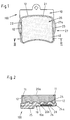
- the brake pad 100 for disc brakes, especially for road and Rail vehicles, according to FIGS. 1 and 2, consists of one in one Carrier plate 10 from a thermoset integrated block 20 from a Friction.
- the carrier plate 10 on one of the two sides of the Friction material block 20 formed and placed.
- the friction material block 20 is not produced on the in a separate operation Carrier plate 10 attached.
- the friction material block is used during manufacture of the carrier plate 10, so to speak, so that the side walls, in particular three contiguous side walls 21, 22, 23 of the Friction material block 20 are encompassed by the material of the carrier plate 10 (Fig. 1).
- the side walls 21, 22, 23 of the friction material block 20 are then surrounded by side walls 12 which are used in the manufacture of the Carrier plate 10 are formed.
- the material of the carrier plate 10 the side walls 21, 22, 23 of the friction material block 20th reaches over into the edge region of the surface 20a free of the carrier plate of the friction material block 20 and here with the material of the friction material block welded.
- These overarching material sections are indicated at 11 (Fig. 2).
- the material of the carrier plate 10, the side walls 21, 22, 23 of the friction material block 20th overlaps, sinters into the material of the friction material block 20, so that an intimate bond between the material of the carrier plate 10th and the material of the friction material block 20 arises.
- thermoset for the production of the carrier plate 10
- Phenoplasts or aminoplasts are used, also by polyaddition and polymerization crosslinking substances or mixtures of substances such as EP and UP resins and PUR product systems can be used.
- the friction material block 20 can have depressions on the underside 20b 24 which are then provided with the material 24a of the carrier plate 10 are filled out.
- the material of the carrier plate 10 thus engages in the material of the friction material block 20 and sinters exactly into the material of the Friction material block 20, so that an intimate bond is created.
- the back 10a of the carrier plate 10 in one geometrically non-uniform shape, namely with bevels or depressions / Increases / impressions 25, etc., which are formed consist of the same material from which the carrier plate is made. It is also possible in the material of the carrier plate 10 materials with a to incorporate another density or to provide inserts 26 so that the noise behavior is influenced.
- the carrier plate 10 and the shape 25 are made of the same materials.
- Inserts 27a e.g. made of metal in the carrier plate 10, the mechanical Properties of the thermoset material support in the Areas in which mechanical properties are particularly necessary are, e.g. in guide surfaces 27 or contact surfaces of the brake piston.
- the insert parts 27a can have a wide variety of geometries.
- the brake (brake piston) can be applied directly to the Carrier plate a separating layer 28 e.g. applied from an elastomer become.
- the elastomer e.g. applied positively to the carrier plate 10 in the injection molding process.
- the separating layer 28 can also be on the elevation 25 and in the Wells on the back 10a of the carrier plate 10 are applied (not shown).
Landscapes
- Engineering & Computer Science (AREA)
- General Engineering & Computer Science (AREA)
- Mechanical Engineering (AREA)
- Braking Arrangements (AREA)
- Laminated Bodies (AREA)
Description
- Fig. 1
- eine Ansicht von oben auf den aus einer Trägerplatte und einem Reibwerkstoffblock bestehenden Bremsbelag und
- Fig. 2
- einen vergrößerten senkrechten Schnitt gemäß Linie II - II in Fig. 1 einer weiteren Ausführungsform.
Claims (10)
- Bremsbelag (100) für Scheibenbremsen, insbesondere für Straßen- und Schienenfahrzeuge, der aus einer Trägerplatte (10) und einem auf dieser befestigten Block (20) aus einem gepreßten Reibwerkstoff besteht, wobei der Reibwerkstoffblock (20) auf der Trägerplatte (10) kraft- und formschlüssig befestigt ist, die aus einem harten, amorphen und bis zur Zersetzungstemperatur starren Kunststoff, der aus räumlich engmaschig vernetzten Makromolekülen mit hoher mechanischer Festigkeit aufgebaut ist, wie z.B. einem Duroplast, besteht, wobei das Material der Trägerplatte (10) mit dem Material des Reibwerkstoffblockes sich verbindet und die Seitenwände des auf der Trägerplatte angeordneten Reibwerkstoffblockes umschließt,
dadurch gekennzeichnet, daß das Material der Trägerplatte (10) in die trägerplattenfreie Oberfläche (20a) des Reibwerkstoffblockes (20) eingreift und die Seitenwände (21, 22,23) des auf der Trägerplatte (10) angeordneten Reibwerkstoffblockes (20) so weit übergreift, dass es in die der Trägerplatte (10) abgewandten Seite des Reibwerkstoffblockes (20) eingreift und mit dem Material des Reibwerkstoffblockes (20) verschweißt ist. - Bremsbelag nach Anspruch 1,
dadurch gekennzeichnet, daß die Trägerplatte (10) im Spritzgußverfahren auf den Reibwerkstoffblock (20) bei gleichzeitiger Ummantelung der Seitenwände (21, 22, 23) des Reibwerkstoffblockes (20) aufgespritzt wird. - Bremsbelag nach einem der Ansprüche 1 und 2,
dadurch gekennzeichnet, daß das Material der Trägerplatte (10), insbesondere das die Seitenwände (21, 22, 23) des Reibwerkstoffblockes (20) umgreifende Material und auch im Oberflächenbereich des Reibwerkstoffblockes (20) in das Material des Reibwerkstoffblockes eingeschmolzen ist. - Bremsbelag nach einem der Ansprüche 1 bis 3,
dadurch gekennzeichnet, daß der Reibwerkstoff (20) an seiner der Trägerplatte (10) zugewandten Unterseite (20b) Einziehungen und/oder Vertiefungen zur Aufnahme von Material (24a) der Trägerplatte (10) aufweist. - Bremsbelag nach einem der Ansprüche 1 bis 3,
dadurch gekennzeichnet, daß der Reibwerkstoff (20) an seiner der Trägerplatte (10) zugewandten Unterseite (20b) eine Profilierung aus Nuten, Rillen oder Rinnen zur Aufnahme von Material der Trägerplatte (10) aufweist. - Bremsbelag nach einem der Ansprüche 1 bis 5,
dadurch gekennzeichnet, daß die Trägerplatte (10) auf ihrer von dem Reibwerkstoff (20) abgewandten Rückseite (10a) Vertiefungen und /oder Erhöhungen (25) aufweist. - Bremsbelag nach einem der Ansprüche 1 bis 5,
dadurch gekennzeichnet, daß die Trägerplatte (10) auf ihrer von dem Reibwerkstoff (20) abgewandten Rückseite (10a) eine Profilierung aus Vertiefungen und/oder Erhöhungen aufweist. - Bremsbelag nach einem der Ansprüche 1 bis 7,
dadurch gekennzeichnet, daß die Trägerplatte (10) mindestens eine Einlage (26) und/oder einen Bereich mit einer vom restlichen Material der Trägerplatte (10) abweichenden Materialdichte aufweist. - Bremsbelag nach einem der Ansprüche 1 bis 8,
dadurch gekennzeichnet, daß die Trägerplatte (10) an einem mechanisch höher beanspruchten Bereich mit mindestens einem Einlegeteil (27a) versehen ist. - Bremsbelag nach einem der Ansprüche 1 bis 9,
dadurch gekennzeichnet, daß die Trägerplatte (10) auf ihrer von dem Reibwerkstoff (20) abgewandten Rückseite (10a) mit einer Trennschicht (28) versehen ist.
Applications Claiming Priority (2)
| Application Number | Priority Date | Filing Date | Title |
|---|---|---|---|
| DE29821482U | 1998-12-02 | ||
| DE29821482U DE29821482U1 (de) | 1998-12-02 | 1998-12-02 | Bremsbelag für Scheibenbremsen |
Publications (3)
| Publication Number | Publication Date |
|---|---|
| EP1006289A2 EP1006289A2 (de) | 2000-06-07 |
| EP1006289A3 EP1006289A3 (de) | 2000-06-28 |
| EP1006289B1 true EP1006289B1 (de) | 2002-06-05 |
Family
ID=8066085
Family Applications (1)
| Application Number | Title | Priority Date | Filing Date |
|---|---|---|---|
| EP99123242A Expired - Lifetime EP1006289B1 (de) | 1998-12-02 | 1999-11-26 | Bremsbelag für Scheibenbremsen |
Country Status (22)
| Country | Link |
|---|---|
| US (1) | US6267206B1 (de) |
| EP (1) | EP1006289B1 (de) |
| JP (1) | JP2000205310A (de) |
| KR (1) | KR20000047852A (de) |
| CN (1) | CN1261036A (de) |
| AT (1) | ATE218680T1 (de) |
| AU (1) | AU6305499A (de) |
| BR (1) | BR9905793A (de) |
| CA (1) | CA2291376A1 (de) |
| DE (2) | DE29821482U1 (de) |
| DK (1) | DK1006289T3 (de) |
| ES (1) | ES2174565T3 (de) |
| FI (1) | FI19992578A7 (de) |
| HR (1) | HRP990374B1 (de) |
| HU (1) | HUP9904442A3 (de) |
| MX (1) | MXPA99011091A (de) |
| NO (1) | NO995857L (de) |
| PL (1) | PL336922A1 (de) |
| RU (1) | RU2229044C2 (de) |
| TR (1) | TR199903023A3 (de) |
| UA (1) | UA68351C2 (de) |
| YU (1) | YU62299A (de) |
Families Citing this family (39)
| Publication number | Priority date | Publication date | Assignee | Title |
|---|---|---|---|---|
| DE29821482U1 (de) * | 1998-12-02 | 2000-04-13 | AlliedSignal Bremsbelag GmbH, 21509 Glinde | Bremsbelag für Scheibenbremsen |
| DE10123004C1 (de) * | 2001-05-11 | 2002-10-17 | Ruetgers Automotive Ag | Brems- oder Kupplungsbelag sowie Verfahren zu seiner Herstellung |
| RU2219393C2 (ru) * | 2001-07-17 | 2003-12-20 | Оао "Тиир" | Колодка дискового тормоза |
| RU2221173C2 (ru) * | 2001-07-30 | 2004-01-10 | Оао "Тиир" | Колодка дискового тормоза |
| MD2262C2 (ro) * | 2002-01-21 | 2004-03-31 | Анатолие СТРАТУЛАТ | Procedeu de recondiţionare a sabotului de frâna cu discuri cu suport complet metalic |
| US20030155193A1 (en) * | 2002-02-20 | 2003-08-21 | Hays William D. | Non-metallic brake plate |
| US6902044B2 (en) * | 2002-10-15 | 2005-06-07 | Arvinmeritor Technology, Llc | Disc pad assembly without backing plate |
| RU2250397C1 (ru) * | 2003-09-22 | 2005-04-20 | Открытое акционерное общество "ТИИР" | Фрикционное изделие |
| US20050161297A1 (en) * | 2004-01-23 | 2005-07-28 | Innovative Technologies, Llc | Brake pad backing plate and method of making the same |
| CA2558163A1 (en) * | 2004-03-03 | 2005-09-15 | Knorr-Bremse Systeme Fur Nutzfahrzeuge Gmbh | Pair of brake linings for a disk brake |
| DE102004018010B3 (de) * | 2004-04-14 | 2005-10-20 | Knorr Bremse Systeme | Magnetschienenbremsvorrichtung |
| DE102004018009B3 (de) * | 2004-04-14 | 2005-10-13 | Knorr-Bremse Systeme für Schienenfahrzeuge GmbH | Magnetschienenbremsvorrichtung |
| ES2320154T3 (es) * | 2004-07-01 | 2009-05-19 | Knorr-Bremse Systeme Fur Schienenfahrzeuge Gmbh | Pastilla de freno para un freno de disco de un vehiculo sobre railes. |
| DE102006004550B4 (de) * | 2006-02-01 | 2016-12-22 | Knorr-Bremse Systeme für Nutzfahrzeuge GmbH | Bremsbelag für eine Scheibenbremse |
| USD573069S1 (en) * | 2006-12-27 | 2008-07-15 | Hayes Bicycle Group, Inc | Bicycle brake pad |
| USD576089S1 (en) * | 2006-12-27 | 2008-09-02 | Hayes Bicycle Group, Inc. | Bicycle brake pad |
| RU2357134C1 (ru) * | 2007-11-28 | 2009-05-27 | Федор Серафимович Темников | Дисковая тормозная колодка |
| IT1396758B1 (it) * | 2009-06-15 | 2012-12-14 | Itt Mfg Enterprises Inc | Pastiglia freno perfezionata |
| DE102009040620B9 (de) | 2009-09-08 | 2024-09-12 | Inno Friction Gmbh | Bremsbelag für Windkraftanlage |
| IT1397971B1 (it) * | 2009-09-17 | 2013-02-04 | Consulplast S R L | Pastiglia freno per freno a disco di veicolo |
| DE102011001562B4 (de) | 2011-03-25 | 2012-12-13 | Dömer GmbH & Co. KG | Reibbelagträgerplatte |
| DE102011115213A1 (de) * | 2011-09-28 | 2013-03-28 | Knorr-Bremse Systeme für Nutzfahrzeuge GmbH | Scheibenbremse, insbesondere für ein Nutzfahrzeug, sowie Bremsbelag für eine Scheibenbremse |
| US20130175127A1 (en) * | 2011-12-19 | 2013-07-11 | Winston MacKelvie | Friction plate |
| KR20150107868A (ko) * | 2013-02-01 | 2015-09-23 | 스미또모 베이크라이트 가부시키가이샤 | 브레이크 패드 및 캘리퍼 장치 |
| CN104968960A (zh) * | 2013-02-01 | 2015-10-07 | 住友电木株式会社 | 制动片和卡钳装置 |
| CN103144647B (zh) * | 2013-02-22 | 2016-08-24 | 山西潞安环保能源开发股份有限公司 | 液压夹钳式制动器 |
| EP2975287A4 (de) * | 2013-03-12 | 2016-12-28 | Sumitomo Bakelite Co | Bremsbelag- und sattelvorrichtung |
| KR102276892B1 (ko) | 2014-05-16 | 2021-07-14 | 프레니 브렘보우 에스.피.에이. | 마찰 조립체, 브레이크 캘리퍼 및 이의 제조 방법 |
| DE102014119489B4 (de) * | 2014-12-23 | 2016-11-03 | Knorr-Bremse Systeme für Schienenfahrzeuge GmbH | Bremsbelag für eine Teilbelag-Scheibenbremse und Anordnung eines Bremsbelags an einem Belaghalter |
| KR20170032684A (ko) | 2015-09-15 | 2017-03-23 | 김준모 | 컨트롤 밸브를 구비한 커먼레일 시스템용 인젝터 재가공 방법 |
| ITUB20160550A1 (it) | 2016-02-08 | 2017-08-08 | Freni Brembo Spa | Assieme di frizione, pinza-freno e metodo di fabbricazione |
| ITUB20160969A1 (it) * | 2016-02-23 | 2017-08-23 | Itt Italia Srl | Supporto metallico per un elemento frenante e pastiglia freno associata |
| CN108626277A (zh) * | 2018-07-01 | 2018-10-09 | 德清县海昌汽车零配件有限公司 | 一种汽车用制动器衬片 |
| EP3594525A1 (de) | 2018-07-12 | 2020-01-15 | MAT Commercial Vehicle Products GmbH | Bremsbelag, scheibenbremsenbaugruppe und fahrzeug |
| DE102018118441A1 (de) * | 2018-07-31 | 2020-02-06 | Tmd Friction Services Gmbh | Verfahren zur Herstellung von Bremsbelägen |
| DE102020106296A1 (de) | 2020-03-09 | 2021-09-23 | Tmd Friction Services Gmbh | Belagträgerplatte für eine Scheibenbremse eines Kraftfahrzeugs sowie Verfahren zur deren Herstellung |
| CN113819173B (zh) * | 2021-09-15 | 2023-05-05 | 杭州科技职业技术学院 | 一种高散热汽车用盘式制动器衬片 |
| IT202100026324A1 (it) | 2021-10-14 | 2023-04-14 | Raicam Driveline S R L | Pastiglia freno con base in materiale plastico |
| DE202022101047U1 (de) | 2022-02-23 | 2023-06-05 | Karsten Fischer | Bremsbelag, bestehend aus einer duroplastischen Trägerplatte und einem Reibbelagblock |
Family Cites Families (15)
| Publication number | Priority date | Publication date | Assignee | Title |
|---|---|---|---|---|
| DE1575930A1 (de) * | 1966-06-30 | 1970-05-14 | Jurid Werke Gmbh | Bremsklotz mit gesintertem Reibkoerper |
| DE2048584A1 (de) * | 1970-10-02 | 1972-04-06 | Bergische Stahlindustrie | Bremsbelag fur Scheibenbremsen |
| FR2406128A1 (fr) * | 1977-07-25 | 1979-05-11 | Abex Pagid Equip | Procede de fabrication de garnitures pour freins a disques |
| US4220223A (en) * | 1978-08-01 | 1980-09-02 | Kelsey Hayes Co. | Sliding caliper disc brake friction pad assemblies |
| FR2441100A2 (fr) * | 1978-11-10 | 1980-06-06 | Abex Pagid Equip | Procede de fabrication de garnitures pour freins a disques |
| AT385824B (de) * | 1979-09-06 | 1988-05-25 | Stahl Kurt | Traegerplatte fuer den belag eines reibblockes fuer scheibenbremsen |
| EP0027714B1 (de) * | 1979-10-19 | 1983-05-25 | LUCAS INDUSTRIES public limited company | Bremsklötze für Fahrzeugscheibenbremsen und Fahrzeugscheibenbremsen |
| FR2498713B1 (fr) * | 1981-01-28 | 1986-04-11 | Abex Pagid Equip | Plaquette de frein a disque |
| DE3124527A1 (de) * | 1981-06-23 | 1983-01-05 | Textar Gmbh, 5090 Leverkusen | Bremsbacke fuer bremsen, insbesondere teilbelagscheibenbremsen |
| US4781275A (en) * | 1984-04-30 | 1988-11-01 | Amsted Industries Incorporated | Composition railway brake shoe |
| US5099962A (en) * | 1990-09-17 | 1992-03-31 | Kabushiki Kaisha Toyota Chuo Kenkyusho | Backing plate for disc brake with different damping layers for brake squeal |
| GB2259553A (en) * | 1991-09-07 | 1993-03-17 | Ferodo Ltd | A disc brake pad |
| RU2011054C1 (ru) * | 1992-03-02 | 1994-04-15 | Сергеев Геннадий Мефодьевич | Фрикционная накладка для дисковых муфт и тормозов |
| US5984055A (en) * | 1997-11-21 | 1999-11-16 | Northrop Grumman Corporation | Integrated fiber reinforced ceramic matrix composite brake pad and back plate |
| DE29821482U1 (de) * | 1998-12-02 | 2000-04-13 | AlliedSignal Bremsbelag GmbH, 21509 Glinde | Bremsbelag für Scheibenbremsen |
-
1998
- 1998-12-02 DE DE29821482U patent/DE29821482U1/de not_active Expired - Lifetime
-
1999
- 1999-11-26 EP EP99123242A patent/EP1006289B1/de not_active Expired - Lifetime
- 1999-11-26 ES ES99123242T patent/ES2174565T3/es not_active Expired - Lifetime
- 1999-11-26 DK DK99123242T patent/DK1006289T3/da active
- 1999-11-26 DE DE59901607T patent/DE59901607D1/de not_active Expired - Lifetime
- 1999-11-26 AT AT99123242T patent/ATE218680T1/de not_active IP Right Cessation
- 1999-11-30 HU HU9904442A patent/HUP9904442A3/hu unknown
- 1999-11-30 NO NO995857A patent/NO995857L/no not_active Application Discontinuation
- 1999-11-30 US US09/451,138 patent/US6267206B1/en not_active Expired - Fee Related
- 1999-12-01 CA CA002291376A patent/CA2291376A1/en not_active Abandoned
- 1999-12-01 HR HR990374A patent/HRP990374B1/xx not_active IP Right Cessation
- 1999-12-01 YU YU62299A patent/YU62299A/sh unknown
- 1999-12-01 CN CN99115973A patent/CN1261036A/zh active Pending
- 1999-12-01 UA UA99126539A patent/UA68351C2/uk unknown
- 1999-12-01 MX MXPA99011091A patent/MXPA99011091A/es unknown
- 1999-12-01 FI FI19992578A patent/FI19992578A7/fi unknown
- 1999-12-01 RU RU99125546/11A patent/RU2229044C2/ru not_active IP Right Cessation
- 1999-12-01 JP JP11342449A patent/JP2000205310A/ja not_active Withdrawn
- 1999-12-02 TR TR1999/03023A patent/TR199903023A3/tr unknown
- 1999-12-02 PL PL99336922A patent/PL336922A1/xx unknown
- 1999-12-02 AU AU63054/99A patent/AU6305499A/en not_active Abandoned
- 1999-12-02 BR BR9905793-0A patent/BR9905793A/pt active Search and Examination
- 1999-12-02 KR KR1019990054377A patent/KR20000047852A/ko not_active Withdrawn
Also Published As
| Publication number | Publication date |
|---|---|
| HU9904442D0 (en) | 2000-02-28 |
| ES2174565T3 (es) | 2002-11-01 |
| BR9905793A (pt) | 2000-09-05 |
| ATE218680T1 (de) | 2002-06-15 |
| CN1261036A (zh) | 2000-07-26 |
| EP1006289A2 (de) | 2000-06-07 |
| FI19992578A7 (fi) | 2000-06-03 |
| NO995857D0 (no) | 1999-11-30 |
| KR20000047852A (ko) | 2000-07-25 |
| UA68351C2 (en) | 2004-08-16 |
| HRP990374A2 (en) | 2000-10-31 |
| JP2000205310A (ja) | 2000-07-25 |
| HUP9904442A3 (en) | 2001-05-28 |
| DK1006289T3 (da) | 2002-07-08 |
| DE59901607D1 (de) | 2002-07-11 |
| NO995857L (no) | 2000-06-05 |
| HRP990374B1 (en) | 2003-10-31 |
| YU62299A (sh) | 2001-03-07 |
| TR199903023A2 (xx) | 2000-07-21 |
| AU6305499A (en) | 2000-06-08 |
| FI19992578L (fi) | 2000-06-02 |
| DE29821482U1 (de) | 2000-04-13 |
| HUP9904442A2 (hu) | 2000-09-28 |
| US6267206B1 (en) | 2001-07-31 |
| RU2229044C2 (ru) | 2004-05-20 |
| MXPA99011091A (es) | 2004-12-01 |
| EP1006289A3 (de) | 2000-06-28 |
| TR199903023A3 (tr) | 2000-07-21 |
| PL336922A1 (en) | 2000-06-05 |
| CA2291376A1 (en) | 2000-06-02 |
Similar Documents
| Publication | Publication Date | Title |
|---|---|---|
| EP1006289A2 (de) | Bremsbelag für Scheibenbremsen | |
| DE69602602T2 (de) | Herstellung von bremsklötzen | |
| EP1982091B1 (de) | Bremselag für eine scheibenbremse | |
| EP2488337B1 (de) | Verfahren zum herstellen eines partikelbasierten elements | |
| EP1593795B1 (de) | Verfahren und Vorrichtung zur Herstellung von flächigen Elementen, insbesondere Bodenelementen | |
| DE112019002953B4 (de) | Bremsbelag, Scheibenbremsenanordnung und Fahrzeug | |
| EP2024157A1 (de) | Verfahren zur herstellung eines bremsbelages und bremsbelag, insbesondere für eine kraftfahrzeugscheibenbremse | |
| EP1256741B1 (de) | Brems- oder Kupplungsbelag sowie Verfahren zu seiner Herstellung | |
| DE1900459A1 (de) | Reibbelag fuer Bremsen,Kupplungen und aehnliche Einrichtungen | |
| EP2459898A1 (de) | Bremsbelag für eine scheibenbremse | |
| AT500252B1 (de) | Gleitbrett, insbesondere ski | |
| DE20014999U1 (de) | Betonschwelle für den Gleisbau | |
| DE2031517B2 (de) | Bremsklotz fur eine Teilbelagscheibenbremse | |
| AT413797B (de) | Gleitbrett, insbesondere ski, und verfahren zur herstellung | |
| DE2236844A1 (de) | Verfahren zur herstellung metallverstaerkter polyesterharzgegenstaende | |
| DE102010009262A1 (de) | Scheibenbremse für ein Nutzfahrzeug | |
| DE10201059B4 (de) | Reibbelag und Verfahren zur Herstellung | |
| DE3444108A1 (de) | Werkzeug zur herstellung von formteilen und dessen verwendung | |
| DE102019208695A1 (de) | Verbund aus einem ersten Fügepartner und einem zweiten Fügepartner | |
| DE19907309A1 (de) | Plattenförmiges Halbzeug mit Unterkonstruktion | |
| DE3034217A1 (de) | Befestigungsteil an ausstattungsteilen fuer fahrzeuge und verfahren zu dessen herstellung | |
| DE29913689U1 (de) | Reibblock für eine Scheibenbremse, insbesondere Scheibenbremse für Schienenfahrzeuge | |
| DE3511878C2 (de) | Verfahren und Vorrichtung zum Herstellen von einbaufertigen Verbindungslaschen für elektrisch leitende Klebestöße an Schienen | |
| EP0665100A1 (de) | Arbeitsplatte | |
| DE102015107562B4 (de) | Verfahren zur Herstellung einer Bremsbacke, Presse zur Herstellung von Bremsbacken sowie Bremsbacke |
Legal Events
| Date | Code | Title | Description |
|---|---|---|---|
| PUAI | Public reference made under article 153(3) epc to a published international application that has entered the european phase |
Free format text: ORIGINAL CODE: 0009012 |
|
| PUAL | Search report despatched |
Free format text: ORIGINAL CODE: 0009013 |
|
| AK | Designated contracting states |
Kind code of ref document: A2 Designated state(s): AT BE CH CY DE DK ES FI FR GB GR IE IT LI LU MC NL PT SE |
|
| AX | Request for extension of the european patent |
Free format text: AL;LT;LV;MK;RO;SI |
|
| AK | Designated contracting states |
Kind code of ref document: A3 Designated state(s): AT BE CH CY DE DK ES FI FR GB GR IE IT LI LU MC NL PT SE |
|
| AX | Request for extension of the european patent |
Free format text: AL;LT;LV;MK;RO;SI |
|
| 17P | Request for examination filed |
Effective date: 20000817 |
|
| 17Q | First examination report despatched |
Effective date: 20010129 |
|
| AKX | Designation fees paid |
Free format text: AT BE CH CY DE DK ES FI FR GB GR IE IT LI LU MC NL PT SE |
|
| GRAG | Despatch of communication of intention to grant |
Free format text: ORIGINAL CODE: EPIDOS AGRA |
|
| GRAG | Despatch of communication of intention to grant |
Free format text: ORIGINAL CODE: EPIDOS AGRA |
|
| GRAH | Despatch of communication of intention to grant a patent |
Free format text: ORIGINAL CODE: EPIDOS IGRA |
|
| GRAH | Despatch of communication of intention to grant a patent |
Free format text: ORIGINAL CODE: EPIDOS IGRA |
|
| GRAA | (expected) grant |
Free format text: ORIGINAL CODE: 0009210 |
|
| AK | Designated contracting states |
Kind code of ref document: B1 Designated state(s): AT BE CH CY DE DK ES FI FR GB GR IE IT LI LU MC NL PT SE |
|
| PG25 | Lapsed in a contracting state [announced via postgrant information from national office to epo] |
Ref country code: IE Free format text: LAPSE BECAUSE OF FAILURE TO SUBMIT A TRANSLATION OF THE DESCRIPTION OR TO PAY THE FEE WITHIN THE PRESCRIBED TIME-LIMIT Effective date: 20020605 Ref country code: GR Free format text: LAPSE BECAUSE OF FAILURE TO SUBMIT A TRANSLATION OF THE DESCRIPTION OR TO PAY THE FEE WITHIN THE PRESCRIBED TIME-LIMIT Effective date: 20020605 Ref country code: FI Free format text: LAPSE BECAUSE OF FAILURE TO SUBMIT A TRANSLATION OF THE DESCRIPTION OR TO PAY THE FEE WITHIN THE PRESCRIBED TIME-LIMIT Effective date: 20020605 |
|
| REF | Corresponds to: |
Ref document number: 218680 Country of ref document: AT Date of ref document: 20020615 Kind code of ref document: T |
|
| REG | Reference to a national code |
Ref country code: GB Ref legal event code: FG4D Free format text: NOT ENGLISH |
|
| REG | Reference to a national code |
Ref country code: CH Ref legal event code: EP |
|
| REG | Reference to a national code |
Ref country code: DK Ref legal event code: T3 |
|
| REG | Reference to a national code |
Ref country code: IE Ref legal event code: FG4D Free format text: GERMAN |
|
| REF | Corresponds to: |
Ref document number: 59901607 Country of ref document: DE Date of ref document: 20020711 |
|
| PG25 | Lapsed in a contracting state [announced via postgrant information from national office to epo] |
Ref country code: PT Free format text: LAPSE BECAUSE OF FAILURE TO SUBMIT A TRANSLATION OF THE DESCRIPTION OR TO PAY THE FEE WITHIN THE PRESCRIBED TIME-LIMIT Effective date: 20020905 |
|
| ET | Fr: translation filed | ||
| REG | Reference to a national code |
Ref country code: ES Ref legal event code: FG2A Ref document number: 2174565 Country of ref document: ES Kind code of ref document: T3 |
|
| PGFP | Annual fee paid to national office [announced via postgrant information from national office to epo] |
Ref country code: DK Payment date: 20021113 Year of fee payment: 4 |
|
| PGFP | Annual fee paid to national office [announced via postgrant information from national office to epo] |
Ref country code: AT Payment date: 20021119 Year of fee payment: 4 |
|
| PGFP | Annual fee paid to national office [announced via postgrant information from national office to epo] |
Ref country code: BE Payment date: 20021120 Year of fee payment: 4 |
|
| PGFP | Annual fee paid to national office [announced via postgrant information from national office to epo] |
Ref country code: SE Payment date: 20021122 Year of fee payment: 4 |
|
| PG25 | Lapsed in a contracting state [announced via postgrant information from national office to epo] |
Ref country code: LU Free format text: LAPSE BECAUSE OF NON-PAYMENT OF DUE FEES Effective date: 20021126 |
|
| PG25 | Lapsed in a contracting state [announced via postgrant information from national office to epo] |
Ref country code: CY Free format text: LAPSE BECAUSE OF FAILURE TO SUBMIT A TRANSLATION OF THE DESCRIPTION OR TO PAY THE FEE WITHIN THE PRESCRIBED TIME-LIMIT Effective date: 20021130 |
|
| REG | Reference to a national code |
Ref country code: IE Ref legal event code: FD4D Ref document number: 1006289E Country of ref document: IE |
|
| PLBE | No opposition filed within time limit |
Free format text: ORIGINAL CODE: 0009261 |
|
| STAA | Information on the status of an ep patent application or granted ep patent |
Free format text: STATUS: NO OPPOSITION FILED WITHIN TIME LIMIT |
|
| 26N | No opposition filed |
Effective date: 20030306 |
|
| PG25 | Lapsed in a contracting state [announced via postgrant information from national office to epo] |
Ref country code: MC Free format text: LAPSE BECAUSE OF NON-PAYMENT OF DUE FEES Effective date: 20030601 |
|
| PG25 | Lapsed in a contracting state [announced via postgrant information from national office to epo] |
Ref country code: AT Free format text: LAPSE BECAUSE OF NON-PAYMENT OF DUE FEES Effective date: 20031126 |
|
| PG25 | Lapsed in a contracting state [announced via postgrant information from national office to epo] |
Ref country code: SE Free format text: LAPSE BECAUSE OF NON-PAYMENT OF DUE FEES Effective date: 20031127 |
|
| PG25 | Lapsed in a contracting state [announced via postgrant information from national office to epo] |
Ref country code: LI Free format text: LAPSE BECAUSE OF NON-PAYMENT OF DUE FEES Effective date: 20031130 Ref country code: CH Free format text: LAPSE BECAUSE OF NON-PAYMENT OF DUE FEES Effective date: 20031130 Ref country code: BE Free format text: LAPSE BECAUSE OF NON-PAYMENT OF DUE FEES Effective date: 20031130 |
|
| PG25 | Lapsed in a contracting state [announced via postgrant information from national office to epo] |
Ref country code: DK Free format text: LAPSE BECAUSE OF NON-PAYMENT OF DUE FEES Effective date: 20031201 |
|
| BERE | Be: lapsed |
Owner name: *ALLIEDSIGNAL BREMSBELAG G.M.B.H. Effective date: 20031130 |
|
| PG25 | Lapsed in a contracting state [announced via postgrant information from national office to epo] |
Ref country code: NL Free format text: LAPSE BECAUSE OF NON-PAYMENT OF DUE FEES Effective date: 20040601 |
|
| EUG | Se: european patent has lapsed | ||
| REG | Reference to a national code |
Ref country code: DK Ref legal event code: EBP |
|
| REG | Reference to a national code |
Ref country code: CH Ref legal event code: PL |
|
| NLV4 | Nl: lapsed or anulled due to non-payment of the annual fee |
Effective date: 20040601 |
|
| PGFP | Annual fee paid to national office [announced via postgrant information from national office to epo] |
Ref country code: FR Payment date: 20061117 Year of fee payment: 8 |
|
| PGFP | Annual fee paid to national office [announced via postgrant information from national office to epo] |
Ref country code: GB Payment date: 20061123 Year of fee payment: 8 Ref country code: ES Payment date: 20061123 Year of fee payment: 8 |
|
| PGFP | Annual fee paid to national office [announced via postgrant information from national office to epo] |
Ref country code: IT Payment date: 20061130 Year of fee payment: 8 |
|
| GBPC | Gb: european patent ceased through non-payment of renewal fee |
Effective date: 20071126 |
|
| REG | Reference to a national code |
Ref country code: FR Ref legal event code: ST Effective date: 20080930 |
|
| PG25 | Lapsed in a contracting state [announced via postgrant information from national office to epo] |
Ref country code: GB Free format text: LAPSE BECAUSE OF NON-PAYMENT OF DUE FEES Effective date: 20071126 |
|
| REG | Reference to a national code |
Ref country code: ES Ref legal event code: FD2A Effective date: 20071127 |
|
| PG25 | Lapsed in a contracting state [announced via postgrant information from national office to epo] |
Ref country code: FR Free format text: LAPSE BECAUSE OF NON-PAYMENT OF DUE FEES Effective date: 20071130 Ref country code: ES Free format text: LAPSE BECAUSE OF NON-PAYMENT OF DUE FEES Effective date: 20071127 |
|
| PG25 | Lapsed in a contracting state [announced via postgrant information from national office to epo] |
Ref country code: IT Free format text: LAPSE BECAUSE OF NON-PAYMENT OF DUE FEES Effective date: 20071126 |
|
| PGFP | Annual fee paid to national office [announced via postgrant information from national office to epo] |
Ref country code: DE Payment date: 20151130 Year of fee payment: 17 |
|
| REG | Reference to a national code |
Ref country code: DE Ref legal event code: R119 Ref document number: 59901607 Country of ref document: DE |
|
| PG25 | Lapsed in a contracting state [announced via postgrant information from national office to epo] |
Ref country code: DE Free format text: LAPSE BECAUSE OF NON-PAYMENT OF DUE FEES Effective date: 20170601 |