EP1004489A2 - Dispositif manuel pour le réaffûtage des balais d'essuie-glace - Google Patents
Dispositif manuel pour le réaffûtage des balais d'essuie-glace Download PDFInfo
- Publication number
- EP1004489A2 EP1004489A2 EP99123360A EP99123360A EP1004489A2 EP 1004489 A2 EP1004489 A2 EP 1004489A2 EP 99123360 A EP99123360 A EP 99123360A EP 99123360 A EP99123360 A EP 99123360A EP 1004489 A2 EP1004489 A2 EP 1004489A2
- Authority
- EP
- European Patent Office
- Prior art keywords
- grinding
- regrinding
- wiper
- wiper lip
- strips
- Prior art date
- Legal status (The legal status is an assumption and is not a legal conclusion. Google has not performed a legal analysis and makes no representation as to the accuracy of the status listed.)
- Withdrawn
Links
- 239000000428 dust Substances 0.000 claims description 4
- 230000002940 repellent Effects 0.000 claims description 2
- 239000005871 repellent Substances 0.000 claims description 2
- 239000000463 material Substances 0.000 abstract description 4
- 230000008901 benefit Effects 0.000 description 6
- 125000006850 spacer group Chemical group 0.000 description 6
- 238000000034 method Methods 0.000 description 3
- 239000004033 plastic Substances 0.000 description 3
- 230000008569 process Effects 0.000 description 3
- 241000238631 Hexapoda Species 0.000 description 2
- XAGFODPZIPBFFR-UHFFFAOYSA-N aluminium Chemical compound [Al] XAGFODPZIPBFFR-UHFFFAOYSA-N 0.000 description 2
- 229910052782 aluminium Inorganic materials 0.000 description 2
- 230000002950 deficient Effects 0.000 description 2
- 210000004905 finger nail Anatomy 0.000 description 2
- 238000002347 injection Methods 0.000 description 2
- 239000007924 injection Substances 0.000 description 2
- 230000007246 mechanism Effects 0.000 description 2
- 239000004576 sand Substances 0.000 description 2
- 206010040925 Skin striae Diseases 0.000 description 1
- 239000004809 Teflon Substances 0.000 description 1
- 229920006362 Teflon® Polymers 0.000 description 1
- 230000009471 action Effects 0.000 description 1
- 238000005452 bending Methods 0.000 description 1
- 238000010276 construction Methods 0.000 description 1
- 230000003111 delayed effect Effects 0.000 description 1
- 230000000694 effects Effects 0.000 description 1
- 238000005516 engineering process Methods 0.000 description 1
- 238000001746 injection moulding Methods 0.000 description 1
- 238000005259 measurement Methods 0.000 description 1
- NJPPVKZQTLUDBO-UHFFFAOYSA-N novaluron Chemical compound C1=C(Cl)C(OC(F)(F)C(OC(F)(F)F)F)=CC=C1NC(=O)NC(=O)C1=C(F)C=CC=C1F NJPPVKZQTLUDBO-UHFFFAOYSA-N 0.000 description 1
- 239000003973 paint Substances 0.000 description 1
- 229920001296 polysiloxane Polymers 0.000 description 1
- 239000002994 raw material Substances 0.000 description 1
- 230000035945 sensitivity Effects 0.000 description 1
- 238000000926 separation method Methods 0.000 description 1
- IHQKEDIOMGYHEB-UHFFFAOYSA-M sodium dimethylarsinate Chemical class [Na+].C[As](C)([O-])=O IHQKEDIOMGYHEB-UHFFFAOYSA-M 0.000 description 1
- 239000000454 talc Substances 0.000 description 1
- 229910052623 talc Inorganic materials 0.000 description 1
- 230000007704 transition Effects 0.000 description 1
- XLYOFNOQVPJJNP-UHFFFAOYSA-N water Substances O XLYOFNOQVPJJNP-UHFFFAOYSA-N 0.000 description 1
Images


Classifications
-
- B—PERFORMING OPERATIONS; TRANSPORTING
- B24—GRINDING; POLISHING
- B24D—TOOLS FOR GRINDING, BUFFING OR SHARPENING
- B24D15/00—Hand tools or other devices for non-rotary grinding, polishing, or stropping
-
- B—PERFORMING OPERATIONS; TRANSPORTING
- B60—VEHICLES IN GENERAL
- B60S—SERVICING, CLEANING, REPAIRING, SUPPORTING, LIFTING, OR MANOEUVRING OF VEHICLES, NOT OTHERWISE PROVIDED FOR
- B60S1/00—Cleaning of vehicles
- B60S1/02—Cleaning windscreens, windows or optical devices
- B60S1/04—Wipers or the like, e.g. scrapers
- B60S1/32—Wipers or the like, e.g. scrapers characterised by constructional features of wiper blade arms or blades
- B60S1/38—Wiper blades
- B60S2001/3846—Devices for renewing or renovating blade wiping edges, e.g. cutters
Definitions
- the invention relates to a device for manual Regrinding wiper blades.
- regrinding devices are from the prior art known.
- German utility model G 94 10 489.1 a regrinding device arranged on a pedestal.
- clamping strips fix the shape of the lip.
- One along the Wiper lip by means of a cylinder moving separation device - for example in Shape of a moving grinding wheel - separates one desired amount of the height of the rubber lip the entire length of the wiper.
- This device there is the disadvantage that first of all the wiper or just the rubber material the bracket of the wiper arm removed must become.
- Another disadvantage is that when regrinding Rubber material along the entire length of the Windshield wiper is separated. It is also disadvantageous that this device is structurally very complex and is therefore very expensive.
- the German Utility model G 82 36 906.2 known.
- the one shown there Device consists of a palm-sized Housing in which an abrasive is used is.
- This abrasive has a continuous Groove on that is essentially the cross-sectional shape a wiper lip.
- the sidewalls of the abrasive support during the grinding process the lip so that it doesn't tip over can. So that the wiper lip is sharp again can be molded is between the side walls of the grinding wheel, another one, here very narrow, grinding surface arranged.
- This device is either over the wiper lip pulled or the wiper is through this Abrasive pulled through. An expansion of the Is from the wiper arm not absolutely necessary here.
- the length of the Grinding surface is shorter than the distance between two support points of a small wiper rocker.
- the small seesaw is used to refer to that seesaw be that directly the rubber body of the wiper lip is facing. Because of the low Expansion of this abrasive in the longitudinal direction the wiper lip, it comes from pressing of the abrasive during the grinding process a deflection of the wiper rubber. In order to the quality is no longer sufficient parallel to the abrasive and so it comes incorrect regrinding of the wiper lip.
- the invention is characterized by the features of the claim 1 solved.
- the inventor has in analyzing the state of the Technology recognized the disadvantages. He came to the realization that a division of the device into a leading / supporting part and a grinding Part that is required. He also realized that good leadership / support is also achieved can, if no extensive standing device is used becomes.
- the device according to the invention there is a bar on either side of the wiper lip. These strips have in terms of their direction of contact to the wiper lip high bending moment of resistance. By entering the wedge-shaped wiper lip in the This gap remains between the two strips therefore in parallel. These strips have one Contact surface or line on the sides of the wiper lip. This contact surface / line is preferably trained such that they essentially parallel to the wedge-shaped side surfaces the wiper lip.
- the strips are connected to each other via bridges, that the ledges together with the bridges form a frame that is one between the strips essentially parallel gap for inclusion the wiper lip. If the wiper arm from the windshield - for example a motor vehicle - is pivoted, so you can use the wipers about 90 degrees around the pivot point of its connection to the Swivel the wiper arm. In this position is every wiper lip for a human easily accessible, which is a great advantage for the handling of the device according to the invention is because this does not remove the wiper required for regrinding is.
- the holding device lies on during grinding Broad sides of the strips. Glide when grinding the undersides of the holding device sledge-shaped on the ledges. At least one resilient element the holding device presses the grinding medium for example on the narrow surface of the wiper lip.
- the spring constant of the spring element is matched so that even with different Height of the wiper lip - measured above the lasts - almost the same Contact pressure comes about.
- the spring element is carried out in a large radius, so that the Point of the wiper lip to be ground through the grinding movement a gently building up Grinding pressure is exposed. Due to the radius shape the resilient element is this advantage also given with reverse grinding movement.
- the harmful grooves are oriented transversely in the wiper lip.
- the Groove depth is usually less than 0.1 mm. Because the scoring often doesn't cover the whole Length of the wiper lip are distributed only regrinding in the lip area required, where the striae are present.
- Through the Radius shape of the resilient element arises gradual transition between the reground and the non-ground area of the wiper lip. Because the removal of the rubber material only in very small amounts is with one only selective regrinding, the surface of the Narrow surface of the wiper lip only marginally wavy. This waveform is created by the Pressing mechanism of the windshield wiper completely balanced so that the contact pressure of the wiper lip on the windshield so fails as if the wiper was brand new.
- the holding device can be like a fingernail brush are held on its side walls. To influence the contact pressure during regrinding, but can also put a finger on that of the narrow surface the wiper lip facing resilient Element of the holding device can be set.
- the holding device will also have two sanding surfaces on the side surfaces the wiper lip. This Grinding surfaces are either reinforced by finger force or only by using your finger to the side of the wiper lips pressed.
- a possibly emerging burr can either be easy to be removed with fingernails or after the Regrind during the first wiping movements of the Wipers wiped.
- the wiper after regrinding cleaned the windshield so that the causers of the grooves, like dried insects, grains of sand or ice or ice remnants are removed.
- the strips form together with the bridges a frame.
- Between Bridges is the free length of the regrinding device with the gap between the bars to accommodate the wedge-shaped wiper lip.
- Regrinding device corresponds to the free one Length is equal to the length of the wiper lip.
- There Wiper lips up to 50 cm long some would feel People a somewhat bulky device. The inventor realized that his device even then still works reliably if the free length the regrinding device approximately three times the distance the smallest rockers or 300 mm corresponds.
- the frame will then only open put on the area of the wiper lip, of the grooves and / or rounded wiping edges having. Is in another area of the wiper lip Regrinding required, see above the frame is simply moved there or offset and regrinding carried out.
- the sanding medium consists of commercially available sandpaper which can be bought anytime and anywhere can be.
- the size of the sandpaper strip required can everyone cut to size.
- the grain of the sandpaper should be 120 or finer. Finer Grinding medium naturally leads to less Burr on the wiper lips, but it increases also the grinding time.
- Another advantage of the device according to the invention is that - with the exception of the grinding medium - all parts in the simplest way Plastic can be made. You can those required for a regrinding device two strips and the two bridges, each with only an injection mold. Also the Holding device for the grinding medium can be in one Injection mold including the integrated one Leaf spring are manufactured. The lasts and bridges are pluggable and clickable so that the user assemble his regrinding device himself can.
- the strips made of drawn aluminum rails manufactured can vary depending on the current prices for the raw materials, compared to the last made of plastic, be cheaper.
- the grinding dust which is partly between the grains of the grinding medium.
- the grinding Surface of the grinding medium with a dust repellent can for example talc, silicone or Teflon his.
- the surface can also be varnished be that also wets the grinding medium, but most of all the narrowest space between fills the grains.
- FIG 1 the handling of the Regrinding device 1 shown.
- the wiper arm 27 was from the windshield 13 so swung far away that the (hidden here) windshield wiper 6 around its pivot point with the wiper arm 27 can be rotated by about 90 degrees.
- the one from the strips 9, 10 and the bridge elements 11, 12 (12 is hidden here) existing frame placed on the wiper lip 5.
- the left Hand holds (for right-handers) both the wiper 6, as well as the frame. With the right one Hand is holding device 7 oscillating over the wiper lip 5 out.
- the regrinding device 1 shown together with the wiper 6 in detail.
- the regrinding device 1 covers it Embodiment the wiper lip 5 and the main part of the wiper blade underneath 2 over the entire length.
- the Wiper lip 5 is located within the free length 24 of the regrinding device 1.
- Am Wiper blade 2 are the small rockers 23 in of the kind movably bracketed that the brackets to some extent represent a joint 28.
- the Small rockers 23 are on joints 28 with the center rockers 25 and these center rockers 25 are again connected to the main rocker 26 via joints 28. This main rocker 26 is finally also over a joint 28 connected to the wiper arm 27.
- FIG. 3 illustrates further details.
- the strips 9 and 10 support the wiper lip 5 on its side surfaces 20, 21 with substantially parallel Support surfaces 3 and 4.
- Below a leaf spring 15 is the grinding medium 8. This is in the Contact with the narrow surface 14 of the wiper lip 5.
- Spring inserts 29 stiffen the Windscreen wiper blade 2. Clamps of the small rocker 23 engage in a groove of the wiper blade on.
- the small rocker 23 is connected via the joint 28 the center rocker 25 connected.
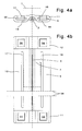
- FIG. 4a is the front view of the frame of the Regrinding device 1.
- the holding device 7 for the grinding medium 8 is only indicated schematically and moves between the guide bars 16 and 17. Since the strips 9 and 10 may also are to be produced by injection molding Guide bars 16, 17 each have a compensation bar 18, 19 assigned to it when the slats cool 9, 10 is not delayed.
- the bridge elements 11, 12 are with an arcuate passage provided for the wiper blade 2. This arcuate Passage is required if the free length 24 of the regrinding device 1 shorter is than the wiper blade 2, otherwise otherwise the bridge elements on the Put on the wiper blade 2.
- the strips 9, 10 engage in recesses in the bridge elements, which can be seen more clearly in FIG. 4b.
- FIG. 4b is the top view of the frame the regrinding device 1 reproduced. The true length has been shortened, which one to be indicated by the break lines 38.
- FIGs 5a to 5c show the side, front and top view of the holding device 7 of the regrinding device 1. With Figures 5d and 5e sections through the holding device 7 are illustrated.
- the slide sidewalls 31, 32 are spaced apart from one another via sidewall spacers 34.
- In the through openings 33 there are holding prongs 36 attached for the grinding medium 8. If - As only drawn in Figure 5e - an abrasive medium 8 around the leaf spring 15 in the manner shown is looped (this makes the grinding surface 39 covered), the holding prongs 36 hinder one by the grinding movement may cause shifting the abrasive medium (preferably sandpaper).
- the through openings 33 are also dimensioned such that a due to the sandpaper elasticity the free ends of the Strip of sandpaper. Thus remains always a wrap of the sandpaper strip to ensure the holding prongs and the grinding medium 8 Sandpaper cannot shift significantly.
- the holding device can be used during regrinding 7 both in the area of grip aids 37 and also for example with ladies and index fingers in the Area between the slide side walls 31, 32 be touched. In the latter case, you have the advantage that about the pressure of the fingers too the grinding pressure can be influenced.
- FIGS. 6a to 6e An alternative to is shown in FIGS. 6a to 6e the holding device 7 from FIGS. 5a to 5e shown.
- the basic shape of the holding device is also here 7 box-shaped again, but are here there are a total of three grinding surfaces 39, 40, 41.
- the grinding surfaces 40 and 41 form a pair, which for the side grinding of the wiper lip 5 is responsible.
- the leaf spring 15 with its grinding surface 39 is designed as a cantilever and ends in the immediate vicinity of the free ends of the grinding surfaces 40, 41. This is crucial Importance and represents a great advantage Dar:
- the grinding surface 39 grinds the narrow surface the wiper lip 5. This creates Grinding burr, which is aligned in the plane in FIG. 6c is.
- this holding device has defined Finger positions 43, 44, 45 on the side and stiffening walls of the device are formed. These finger positions make handling easier the holding device and the sensitivity while grinding.
- FIGS. 7a and 7b An embodiment is shown in FIGS. 7a and 7b the strips 9, 10 shown from drawn aluminum profile.
- the strips are only in the Plastic existing bridge elements 11, 12 pressed.
- the strips in their end area with a grained surface, or glued in, or provided with oversize.
Landscapes
- Engineering & Computer Science (AREA)
- Mechanical Engineering (AREA)
- Finish Polishing, Edge Sharpening, And Grinding By Specific Grinding Devices (AREA)
- Cleaning In General (AREA)
Applications Claiming Priority (2)
| Application Number | Priority Date | Filing Date | Title |
|---|---|---|---|
| DE19853877 | 1998-11-23 | ||
| DE1998153877 DE19853877C2 (de) | 1998-11-23 | 1998-11-23 | Manuelle Nachschleifvorrichtung für Scheibenwischerblätter |
Publications (2)
| Publication Number | Publication Date |
|---|---|
| EP1004489A2 true EP1004489A2 (fr) | 2000-05-31 |
| EP1004489A3 EP1004489A3 (fr) | 2000-06-07 |
Family
ID=7888647
Family Applications (1)
| Application Number | Title | Priority Date | Filing Date |
|---|---|---|---|
| EP99123360A Withdrawn EP1004489A3 (fr) | 1998-11-23 | 1999-11-23 | Dispositif manuel pour le réaffûtage des balais d'essuie-glace |
Country Status (2)
| Country | Link |
|---|---|
| EP (1) | EP1004489A3 (fr) |
| DE (1) | DE19853877C2 (fr) |
Families Citing this family (1)
| Publication number | Priority date | Publication date | Assignee | Title |
|---|---|---|---|---|
| DE19931259C2 (de) * | 1999-07-07 | 2003-03-06 | Klaus-Dieter Wegner | Vorrichtung zum Schleifen von Wischerblättern von Scheibenwischern und Fensterputzvorrichtungen |
Citations (2)
| Publication number | Priority date | Publication date | Assignee | Title |
|---|---|---|---|---|
| DE8236906U1 (de) | 1982-12-31 | 1983-04-14 | Löhr, Günter, 5780 Bestwig | Schleifstein fuer scheibenwischer |
| DE9410489U1 (de) | 1994-06-29 | 1994-09-29 | Hommer, Arnim, 56305 Puderbach | Einrichtung zum Nacharbeiten der Wischerblätter von Kraftfahrzeug-Scheibenwischern |
Family Cites Families (4)
| Publication number | Priority date | Publication date | Assignee | Title |
|---|---|---|---|---|
| US2973577A (en) * | 1959-09-11 | 1961-03-07 | Herbert O Schekowski | Windshield wiper blade trimming device |
| US3886657A (en) * | 1974-02-28 | 1975-06-03 | Ralf Fabian | Windshield wiper sharpener |
| US4604802A (en) * | 1984-10-22 | 1986-08-12 | Soren Samuelsson | Squeegee blade trimmer |
| DE29622514U1 (de) * | 1996-12-28 | 1997-03-13 | Baraniak, Rainer, 06766 Thalheim | Scheibenwischblattschärfer für Autoscheibenwischer |
-
1998
- 1998-11-23 DE DE1998153877 patent/DE19853877C2/de not_active Expired - Fee Related
-
1999
- 1999-11-23 EP EP99123360A patent/EP1004489A3/fr not_active Withdrawn
Patent Citations (2)
| Publication number | Priority date | Publication date | Assignee | Title |
|---|---|---|---|---|
| DE8236906U1 (de) | 1982-12-31 | 1983-04-14 | Löhr, Günter, 5780 Bestwig | Schleifstein fuer scheibenwischer |
| DE9410489U1 (de) | 1994-06-29 | 1994-09-29 | Hommer, Arnim, 56305 Puderbach | Einrichtung zum Nacharbeiten der Wischerblätter von Kraftfahrzeug-Scheibenwischern |
Also Published As
| Publication number | Publication date |
|---|---|
| DE19853877A1 (de) | 1999-05-20 |
| DE19853877C2 (de) | 2000-06-08 |
| EP1004489A3 (fr) | 2000-06-07 |
Similar Documents
| Publication | Publication Date | Title |
|---|---|---|
| EP1289805B1 (fr) | Raclette d'essuie-glace pour le nettoyage de vitres de vehicules | |
| DE10291817B4 (de) | Wischblatt zum Reinigen von Scheiben, insbesondere von Kraftfahrzeugen | |
| DE10025708A1 (de) | Wischblatt zum Reinigen von Fahrzeugscheiben | |
| DE10000381A1 (de) | Wischblatt zum Reinigen von Scheiben an Fahrzeugen, insbesondere Kraftfahrzeugen | |
| DE10000373B4 (de) | Wischblatt zum Reinigen von Scheiben an Fahrzeugen | |
| WO1997035751A1 (fr) | Balai d'essuie-glace pour systeme d'essuie-glace de vehicule | |
| WO2001049537A2 (fr) | Dispositif d'essuyage permettant de nettoyer des vitres de vehicules, notamment d'automobiles | |
| DE3817391C2 (de) | Gleitschuh für Fahrzeug-Schiebedächer | |
| DE3733486A1 (de) | Rasierschneidkopf | |
| DE10014803B4 (de) | Wischerblatt | |
| DE29903123U1 (de) | Scheibenwischer für Fahrzeuge aller Art | |
| EP1004489A2 (fr) | Dispositif manuel pour le réaffûtage des balais d'essuie-glace | |
| DE3642065C2 (de) | Vorrichtung zum Reinigen des Scheibenwischerblatts eines Fahrzeuges | |
| DE10007800A1 (de) | Wischblatt | |
| DE60018975T2 (de) | Linearwischeranlage mit verbessertem führungsmittel des wagens in der führungsscchiene | |
| EP0825077A1 (fr) | Dispositif de nettoyage de pare-brise d'un véhicule avec moyens améliorés de pression du balai | |
| DE9207230U1 (de) | Scheibenwischerhobel | |
| DE2815244A1 (de) | Abdichtungsvorrichtung fuer tueren o.dgl. | |
| DE29820887U1 (de) | Manuelle Nachschleifvorrichtung für Scheibenwischerblätter | |
| DE10257553A1 (de) | Wischblatt | |
| DE19961373A1 (de) | Wischerblatt zur Anordnung an einem Wischerarm | |
| DE8800255U1 (de) | Absperrarmatur | |
| DE10007811A1 (de) | Wischblatt | |
| DE10000388A1 (de) | Wischblatt zum Reinigen von Scheiben an Fahrzeugen, insbesondere Kraftfahrzeugen sowie Federschienensatz zur Verwendung bei einem solchen Wischblatt | |
| DE2610941A1 (de) | Scheibenwischer |
Legal Events
| Date | Code | Title | Description |
|---|---|---|---|
| PUAI | Public reference made under article 153(3) epc to a published international application that has entered the european phase |
Free format text: ORIGINAL CODE: 0009012 |
|
| PUAL | Search report despatched |
Free format text: ORIGINAL CODE: 0009013 |
|
| AK | Designated contracting states |
Kind code of ref document: A2 Designated state(s): AT BE CH CY DE DK ES FI FR GB GR IE IT LI LU MC NL PT SE |
|
| AX | Request for extension of the european patent |
Free format text: AL;LT;LV;MK;RO;SI |
|
| AK | Designated contracting states |
Kind code of ref document: A3 Designated state(s): AT BE CH CY DE DK ES FI FR GB GR IE IT LI LU MC NL PT SE |
|
| AX | Request for extension of the european patent |
Free format text: AL;LT;LV;MK;RO;SI |
|
| AKX | Designation fees paid | ||
| REG | Reference to a national code |
Ref country code: DE Ref legal event code: 8566 |
|
| STAA | Information on the status of an ep patent application or granted ep patent |
Free format text: STATUS: THE APPLICATION IS DEEMED TO BE WITHDRAWN |
|
| 18D | Application deemed to be withdrawn |
Effective date: 20001208 |