EP1003977B1 - Verschlusshülse für eine klemmvorrichtung zum lösbaren verbinden zweier profilstücke - Google Patents
Verschlusshülse für eine klemmvorrichtung zum lösbaren verbinden zweier profilstücke Download PDFInfo
- Publication number
- EP1003977B1 EP1003977B1 EP98936064A EP98936064A EP1003977B1 EP 1003977 B1 EP1003977 B1 EP 1003977B1 EP 98936064 A EP98936064 A EP 98936064A EP 98936064 A EP98936064 A EP 98936064A EP 1003977 B1 EP1003977 B1 EP 1003977B1
- Authority
- EP
- European Patent Office
- Prior art keywords
- clamping device
- sleeve
- closure
- closure sleeve
- wall plate
- Prior art date
- Legal status (The legal status is an assumption and is not a legal conclusion. Google has not performed a legal analysis and makes no representation as to the accuracy of the status listed.)
- Expired - Lifetime
Links
- 230000000295 complement effect Effects 0.000 claims description 6
- 239000000463 material Substances 0.000 abstract description 6
- 241000209035 Ilex Species 0.000 description 19
- 238000010276 construction Methods 0.000 description 4
- 238000003801 milling Methods 0.000 description 4
- 239000002023 wood Substances 0.000 description 4
- 229910052751 metal Inorganic materials 0.000 description 3
- 239000002184 metal Substances 0.000 description 3
- 238000010521 absorption reaction Methods 0.000 description 2
- 230000000694 effects Effects 0.000 description 2
- 238000007789 sealing Methods 0.000 description 2
- 229910052782 aluminium Inorganic materials 0.000 description 1
- XAGFODPZIPBFFR-UHFFFAOYSA-N aluminium Chemical compound [Al] XAGFODPZIPBFFR-UHFFFAOYSA-N 0.000 description 1
- 239000011324 bead Substances 0.000 description 1
- 230000001419 dependent effect Effects 0.000 description 1
- 238000003780 insertion Methods 0.000 description 1
- 230000037431 insertion Effects 0.000 description 1
- 238000009434 installation Methods 0.000 description 1
- 239000007769 metal material Substances 0.000 description 1
- 230000000149 penetrating effect Effects 0.000 description 1
Images


Classifications
-
- F—MECHANICAL ENGINEERING; LIGHTING; HEATING; WEAPONS; BLASTING
- F16—ENGINEERING ELEMENTS AND UNITS; GENERAL MEASURES FOR PRODUCING AND MAINTAINING EFFECTIVE FUNCTIONING OF MACHINES OR INSTALLATIONS; THERMAL INSULATION IN GENERAL
- F16B—DEVICES FOR FASTENING OR SECURING CONSTRUCTIONAL ELEMENTS OR MACHINE PARTS TOGETHER, e.g. NAILS, BOLTS, CIRCLIPS, CLAMPS, CLIPS OR WEDGES; JOINTS OR JOINTING
- F16B7/00—Connections of rods or tubes, e.g. of non-circular section, mutually, including resilient connections
- F16B7/04—Clamping or clipping connections
- F16B7/044—Clamping or clipping connections for rods or tubes being in angled relationship
- F16B7/0446—Clamping or clipping connections for rods or tubes being in angled relationship for tubes using the innerside thereof
- F16B7/0453—Clamping or clipping connections for rods or tubes being in angled relationship for tubes using the innerside thereof the tubes being drawn towards each other
- F16B7/046—Clamping or clipping connections for rods or tubes being in angled relationship for tubes using the innerside thereof the tubes being drawn towards each other by rotating an eccenter-mechanism
-
- F—MECHANICAL ENGINEERING; LIGHTING; HEATING; WEAPONS; BLASTING
- F16—ENGINEERING ELEMENTS AND UNITS; GENERAL MEASURES FOR PRODUCING AND MAINTAINING EFFECTIVE FUNCTIONING OF MACHINES OR INSTALLATIONS; THERMAL INSULATION IN GENERAL
- F16B—DEVICES FOR FASTENING OR SECURING CONSTRUCTIONAL ELEMENTS OR MACHINE PARTS TOGETHER, e.g. NAILS, BOLTS, CIRCLIPS, CLAMPS, CLIPS OR WEDGES; JOINTS OR JOINTING
- F16B5/00—Joining sheets or plates, e.g. panels, to one another or to strips or bars parallel to them
- F16B5/06—Joining sheets or plates, e.g. panels, to one another or to strips or bars parallel to them by means of clamps or clips
- F16B5/0685—Joining sheets or plates to strips or bars
-
- Y—GENERAL TAGGING OF NEW TECHNOLOGICAL DEVELOPMENTS; GENERAL TAGGING OF CROSS-SECTIONAL TECHNOLOGIES SPANNING OVER SEVERAL SECTIONS OF THE IPC; TECHNICAL SUBJECTS COVERED BY FORMER USPC CROSS-REFERENCE ART COLLECTIONS [XRACs] AND DIGESTS
- Y10—TECHNICAL SUBJECTS COVERED BY FORMER USPC
- Y10T—TECHNICAL SUBJECTS COVERED BY FORMER US CLASSIFICATION
- Y10T403/00—Joints and connections
- Y10T403/59—Manually releaseable latch type
- Y10T403/591—Manually releaseable latch type having operating mechanism
-
- Y—GENERAL TAGGING OF NEW TECHNOLOGICAL DEVELOPMENTS; GENERAL TAGGING OF CROSS-SECTIONAL TECHNOLOGIES SPANNING OVER SEVERAL SECTIONS OF THE IPC; TECHNICAL SUBJECTS COVERED BY FORMER USPC CROSS-REFERENCE ART COLLECTIONS [XRACs] AND DIGESTS
- Y10—TECHNICAL SUBJECTS COVERED BY FORMER USPC
- Y10T—TECHNICAL SUBJECTS COVERED BY FORMER US CLASSIFICATION
- Y10T403/00—Joints and connections
- Y10T403/59—Manually releaseable latch type
- Y10T403/598—Transversely sliding pin
Definitions
- the present invention relates to a device for detachable Connecting two profile pieces with a clamping device that in an opening provided in a profile piece can be inserted with a closure sleeve, which is used for the positive reception of the body the clamping device has a recess, and with an operating button with which the clamping device in the closure sleeve can be locked.
- Such a device is known from DE 28 04 222, in which a connection fitting for furniture parts is described with which a clamping pin embedded in a profile piece through a locking sleeve is locked, with a rotation of the closure sleeve an engagement spiral of the same in annular grooves of the Clamping pin engages.
- the devices mentioned are for a multiple opening and closing Dismantling, as is necessary in exhibition stand construction, is not suitable.
- a clamping device of the type mentioned above is for stand construction known for example from WO 97/25536 by the applicant.
- Such Clamping devices are provided for two profile pieces with each other connect to. On the one hand, this is usually the case around a profiled rod to which a wall profile is attached becomes.
- an internal milling is provided in which the clamping device can be inserted up to the protruding hook elements can.
- On one side of the wall surface is for one out of the Known clamping device WO 97/25536 provided a round bore, through which the locking head extends, after opposing the action of a spring force in the clamp countersunk through the cut to the hole into which it snaps into place.
- Said control button also absorbs tensile forces acting on the Act on the wall plate and separate it from the profile strip to attempt.
- the invention is based on the above-mentioned prior art therefore the task is based on devices of the aforementioned Art so that they can be used for frequent Construction and dismantling are suitable and at the same time with non-metallic Materials such as Wood, can be used.
- control button in the Clamping device is provided that the closure sleeve a Has control button receptacle hole, and that the control button in the transverse direction to the longitudinal axis of the clamping device against a spring force can be inserted into the body of the clamping device.
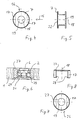
- FIG. 1 shows a top view of a wall panel 1 introduced clamping device 2, of which only the clamping hook 3 protrude beyond the front wall panel edge 24.
- the reference symbol 14 is a profiled rod in which the clamp hooks 3 are releasably hooked.
- the clamping device 2 is in a milling marked with the reference number 5 embedded in the wall plate 1.
- the structure of the clamping device 2 can be found in WO 97/25536.
- An essential one Characteristic of the clamping device 2 is the head 6, which against the Effect of a spring force in the body of the clamping device 2 sunk and then inserted through the milling 5 into the wall plate 1 becomes. This head 6 then protrudes into a transverse bore in the Wall plate 1 into it, advantageously with the wall plate 1 is flush.
- Reference number 7 denotes the sleeve, its function is explained in connection with the other drawings.
- Fig. 2 shows a cross section along the line II-II of Fig. 1, wherein the same features with the same reference numerals Marked are. It can be clearly seen that the Clamping device 2 is pushed into the cutout 5 and that the head 6 of the clamping device 2 is flush with the surface 8 closes the wall plate 1, with a cylindrical around the axis 9 Bore 10 is provided in the before insertion of the Clamping device 2, the sleeve 7 is to be used.
- FIG. 3 is a cross section along the line III-III 1 shown.
- 4 shows the sleeve 7 in one Top view. 5, which is the same sleeve 7 in the side view from the direction 15 shows.
- the cylindrical sleeve 7 via a penetrating here has rectangular bore 16 on both sides in each case in plan view a circular section 17 of material left to stand for.
- Through the bore 16 is the body of the clamping device 2 can be pushed forward.
- Concentric to the axis of symmetry 18 of the cylinder of the sleeve 7, a receiving bore 19 is provided, whose diameter is adjusted so that the head 6 of the Clamping device 2 essentially fits into it.
- FIGS. 1 to 3 From the representation of the sleeve 7, its mode of operation is related with FIGS. 1 to 3 immediately clear.
- the force absorption in one of the directions of the double arrow 20 in FIG. 1 or 3 is through the large side surfaces of the clamping device 2 guaranteed.
- This force usually corresponds the weight of the wall panels 1, which via the clamping device 2 to be attached to profiled rods 14.
- the inventive sleeve to a clamping device also for trays / shelves and base plates or others are used for supporting areal elements, and here especially in exhibition stand construction.
- the area is greatly increased, about which forces can be absorbed, which in one of the Directions of the double arrow 12 act, i.e. essentially Tensile forces that remove the wall plate 1 from the profiled rod could into which the clamping hook 3 of the clamping device 2nd intervention.
- the stressed area of the sleeve 7 corresponds to train in the projection in Fig. 4 of the area in the Level of arrow 15 is arranged. This has thus the design chosen in the exemplary embodiment more than doubled.
- this area which is indicated in FIG. 14 by the reference symbol 11 is marked, also occur and in particular the surface areas identified by reference numeral 31 of the circular segment sections 17 in the jacket.
- the base 22 of the sleeve 7 is an abutment, which a Tilting of the head 6 in the sleeve 7 or of the sleeve 7 with respect the wall plate 1 safely prevented.
- the wall plate 1 a Retains bottom portion 21 so that the sleeve 27 only from the Top, i.e. only recognizable from one side in the wall plate is.
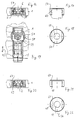
- FIGS. 7 and 8 in the representation of the sleeve 27 can be seen, it now has its recess 26 no longer via a base plate 22, but via two elongated ones Undercuts 28 in the corresponding in the clamping device Engage 2 grooves 29 provided.
- FIG. 9 shows a third embodiment of the invention, in which the height of the sleeve 37 provided here is reduced once again so that the undercuts 38 approximate half the height of the clamping device 2 in a corresponding provided groove 39 of this engage.
- the hole is too here formed into a U-shaped recess 26.
- 10 and 11 to see that the enlargement of the The effective area can also be guaranteed with a very low overall height of the sleeve is.
- the sleeve 7 not cylindrical, but angular, especially rectangular. Besides one Rectangle can also use other polygons for the outer shape of the sleeve to get voted. 12 gives a corresponding sketch reflected in the top view.
- This sleeve 47 can correspond to the first mentioned exemplary embodiments have different heights, through the plate 1 completely or undercuts exhibit. It is important in any case that a front Edge surface 48, which is perpendicular to the direction of arrow 12 lying surface larger than the diameter of the bore 49 through which the head 6 of the clamping device 2 protrudes. With the reference numeral 50 is in the sleeve 47 for the clamping device 2 designated bore designated.
- the Sleeve 47 of course requires the provision of one accordingly opening drilled at right angles in the wall plate 1.
- the lateral areas 48 which consist of a profile piece 1 Record the tractive force and use the control button 6 in the Introduce the clamping device 2 and then into the profiled rod 14.
- the head 6 is also like a honeycomb structure or an octagon possible.
- the hole 49 for the head 6 to the requirements of this one other head 6 having an outer shape can be adapted, whereby to fix the clamping device 2 and the clamping hook 3rd in a profiled rod 1, of course, the circular shape of the head 6 is preferred because it is thus easy to turn.
- FIG. 13 shows a perspective view of one with a Sleeve 7 according to the invention equipped clamping device 2, which is inserted in a wall plate 1, in front of a profiled Rod 14. The front rests after assembly 24 of the plate 1 on the profiled rod 14.
- FIGS. 1 and 13 shows a perspective view of the clamping device 2 with closure sleeve 7 according to FIGS. 1 and 13 in assembled Status.
- areas 11 and 31 can be recognized that protrude laterally beyond the clamping device 2 and thus after installation in the material of the wall plate 1 rest and are suitable for force absorption.
- clamping device 15 shows an exploded view of clamping device 2, Closure sleeve 7 and wall plate 1 according to FIG. 1 before assembly.
- the through bore 10 and the milling 5 can be seen in which the closure sleeve 7 in this order and the clamping device 2 are used.
- any clamping device can be a cuboid shape like the clamping device 2 Has.
- the clamping device can also be, for example have cylindrical body.
- FIG. 16 shows a cross section corresponding to FIG. 3 Wall plate 1, clamping device 2 and a sleeve 57 according to one fifth embodiment of the invention.
- the Clamping device 2 laterally each over the outer edge of the Housing of the clamping device 2 overlooking sections 58, the better in the partially cut top view of the clamping device 2 can be seen in FIG. 19.
- These sections 58 are part of the longitudinally movable slide 59.
- FIG. 17 shows a side view of the sleeve 57
- FIG. 18 shows a plan view of this sleeve 57. that laterally at the appropriate height and complementary to the sections 58 longitudinal grooves 60 are provided, which function as Undercuts 28 and 38 meet.
- the height is preferred the sleeve 57 thus as high as the height of the clamping device 2 with head 6.
- FIG Surface directed in the pull-in or pull-out direction 12 with the reference symbol 51 provided.
- FIG. 20 shows a cross section corresponding to FIG. 3 through wall plate 1, clamping device 2 and sleeve 67 according to one sixth embodiment of the invention
- FIG. 21 being a Side view
- Fig. 22 is a plan view of the sleeve 67 to Figure 20 illustrates.
- the clamping device 2 has rounded Side edges and in particular rounded lower side edges 69 on. These act together with undercuts 68 of the sleeve 67, which have the same complementary radius of curvature.
- FIG. 23 shows an exploded view of a clamping device 2 with a lock housing 92, a thin wall plate 91 and a closure sleeve 77 according to a seventh embodiment.
- the sleeve 77 is like the sleeve 57 with a groove 60 provided with protruding elements 58 of the clamping device 2 interact.
- a lock housing 92 is provided, which has a continuous cavity 93 with grooves 94 for which has elements 58.
- opening 95 is provided for receiving the sleeve 77.
- the complementary Form in the wall plate 91 is excluded. You can the mass of the closure housing 92 in another embodiment also be chosen so that the circular segment Recess 99 in the wall plate 91 is dispensed with.
- FIG. 24 finally shows an exploded view of one Clamping device 2 with a further closure housing 92, one thin wall plate 91 and a closure sleeve 87 according to one eighth embodiment.
- This embodiment is very similar to that from Fig. 23. The differences lie in that the sleeve 87 has two sections 84 and 85 with different Circle diameters. The back or the bottom Section 84 is smaller and forms part of the surface the groove 98. The upper larger section 85 takes a place in Lock housing 92, which in the lock housing 92 after 23 has been filled in by the latter itself. So that's one space-saving design of the clamping device 2 with the sleeve 87 possible for the thin wall plate 91.
- the sleeves intended for use with the closure housing 92 77 and 87 can of course also correspond to other embodiments and in particular according to the sleeves 7, 27, 37, 47, 57 and 67. Then in particular on the Groove 94 can be dispensed with if the clamping device 2 has none has protruding sections 58.
- the sleeves 7, 27, 37, 47, 57, 67, 77 and 87 and the sealing sleeve 92 preferably consist of a light metal, e.g. Aluminum. But you can also use any other material be made, especially from plastic. In summary these sleeves have the advantage that with such a closure sleeve 7, 27, 37, 47, 57, 67, 77 and 87 Clamping devices 2 considerably better in the longitudinal direction 12 of the Resist clamping device 2 acting tensile forces. With that Clamping devices 2 of the type mentioned now also with other materials the profile pieces 1, e.g. Wood, can be used. Through commitment a closure sleeve 92 can now also very thin profile elements 1, such as thin wooden panels 91, are used come.
- a closure sleeve 92 can now also very thin profile elements 1, such as thin wooden panels 91, are used come.
Description
- Fig. 1
- eine in eine Wandplatte eingeführte Klemmvorrichtung mit einer erfindungsgemässen Hülse in einer Draufsicht gemäss einem ersten Ausführungsbeispiel,
- Fig. 2
- die Wandplatte, Klemmvorrichtung und Hülse nach Fig. 1 in einem Querschnitt entlang der Linie II-II,
- Fig. 3
- dieselben Elemente nach Fig. 1 in einem Querschnitt entlang der Linie III-III,
- Fig. 4
- eine Draufsicht auf eine Hülse, wie sie im ersten Ausführungsbeispiel nach Fig. 1 bis 3 verwendet wird,
- Fig. 5
- eine Seitenansicht der Hülse nach Fig. 4,
- Fig. 6
- ein Fig. 3 entsprechender Querschnitt durch Wandplatte, Klemmvorrichtung und Hülse gemäss einem zweiten Ausführungsbeispiel der Erfindung,
- Fig. 7
- eine Draufsicht auf eine Hülse gemäss dem zweiten Ausführungsbeispiel,
- Fig. 8
- eine Seitenansicht der Hülse nach Fig. 7,
- Fig. 9
- ein Fig. 3 entsprechender Querschnitt durch Wandplatte, Klemmvorrichtung und Hülse gemäss einem dritten Ausführungsbeispiel der Erfindung,
- Fig. 10
- eine Draufsicht auf eine Hülse gemass dem dritten Ausführungsbeispiel,
- Fig. 11
- eine Seitenansicht der Hülse nach Fig. 10,
- Fig. 12
- eine Draufsicht auf eine Hülse gemäss einem vierten Ausführungsbeispiel der Erfindung,
- Fig. 13
- eine perspektivische Ansicht einer mit einer Hülse gemäss der Erfindung ausgestatteten Wandplatte mit einer profilierten Stange,
- Fig. 14
- eine perspektivische Ansicht der Klemmvorrichtung mit Verschlusshülse nach Fig. 1,
- Fig. 15
- eine Explosionsansicht von Klemmvorrichtung, Verschlusshülse und Wandplatte nach Fig. 1,
- Fig. 16
- ein Fig. 3 entsprechender Querschnitt durch Wandplatte, Klemmvorrichtung und Hülse gemäss einem fünften Ausführungsbeispiel der Erfindung,
- Fig. 17
- eine Seitenansicht einer Hülse gemass dem fünften Ausführungsbeispiei,
- Fig. 18
- eine Draufsicht auf die Hülse nach Fig. 16,
- Fig. 19
- die Klemmvorrichtung mit der erfindungsgemässen Hülse nach Fig. 16 in einer teilweise geschnittenen Draufsicht,
- Fig. 20
- ein Fig. 3 entsprechender Querschnitt durch Wandplatte, Klemmvorrichtung und Hülse gemäss einem sechsten Ausführungsbeispiel der Erfindung,
- Fig. 21
- eine Seitenansicht einer Hülse gemäss dem sechsten Ausführungsbeispiel,
- Fig. 22
- eine Draufsicht auf die Hülse nach Fig. 20,
- Fig. 23
- eine Explosionsansicht von Klemmvorrichtung mit einem Verschlussgehäuse, einer dünnen Wandplatte und einer Verschlusshülse gemäss einem siebten Ausführungsbeispiel, und
- Fig. 24
- eine Explosionsansicht von Klemmvorrichtung mit einem Verschlussgehäuse, einer dünnen Wandplatte und einer Verschlusshülse gemäss einem achten Ausführungsbeispiel.
Claims (9)
- Vorrichtung zum lösbaren Verbinden zweier Profilstücke (1, 91 und 14) mit einer Klemmvorrichtung (2), die in eine in einem Profilstück (1, 91) vorgesehene Öffnung (5) einführbar ist, mit einer Verschlusshülse (7, 27, 37, 47, 57, 67, 77, 87), die zur formschlüssigen Aufnahme des Körpers der Klemmvorrichtung (2) über eine Ausnehmung (16, 50) verfügt, und mit einem Bedienknopf, mit dem die Klemmvorrichtung (2) in der Verschlusshülse (7, 27, 37, 47, 57, 67, 77, 87) arretierbar ist, dadurch gekennzeichnet, dass der Bedienknopf (6) in der Klemmvorrichtung (2) vorgesehen ist, dass die Verschlusshülse (7, 27, 37, 47, 57, 67, 77, 87) eine den Bedienknopf (6) aufnehmbare Bohrung (19) aufweist, und dass der Bedienknopf (6) in Querrichtung zur Längsachse der Klemmvorrichtung (2) gegen eine Federkraft in den Körper der Klemmvorrichtung (2) einschiebbar ist.
- Vorrichtung nach Anspruch 1, dadurch gekennzeichnet, dass die Aussenform der Verschlusshülse (7, 27, 37, 57, 67) ein Zylinder ist.
- Vorrichtung nach Anspruch 1, dadurch gekennzeichnet, dass die Aussenform der Verschlusshülse (47) ein Vieleck ist.
- Vorrichtung nach einem der Ansprüche 1 bis 3, dadurch gekenn-zeichnet, dass die Ausnehmung (16, 50) eine Bohrung ist, so dass die Verschlusshülse (7) über einen der Bohrung (19) gegenüberliegenden Boden (22) verfügt.
- Vorrichtung nach einem der Ansprüche 1 bis 3, dadurch gekennzeichnet, dass die Ausnehmung (26) so ausgestaltet ist, dass von der Verschlusshülse (27, 37, 67) ein im Querschnitt U-förmiger Teil verbleibt; und dass die Verschlusshülse (27, 37, 67) Hinterschneidungen (28, 38, 68) aufweist, die mit komplementären Nuten (29, 39, 69) der Klemmvorrichtung (2) zusammenwirken.
- Vorrichtung nach einem der Ansprüche 1 bis 3, dadurch gekennzeichnet, dass die Verschlusshülse (57, 77, 87) über seitlich in Einführungsrichtung (12) verlaufende Nuten (60) verfügt, die mit komplementären Abschnitten (58) der Klemmvorrichtung (2) zusammenwirken.
- Verschlussgehäuse für eine Vorrichtung nach einem der vorstehenden Ansprüche, dadurch gekennzeichnet, dass das Verschlussgehäuse (92) einen Hohlraum (93) zur Aufnahme der Klemmvorrichtung (2), eine quer zu deren Längsrichtung ausgerichtete Öffnung (95) zur Aufnahme der Verschlusshülse (77, 87) und an seinen Schmalseiten in Längsrichtung verlaufende Nuten (98) zur Aufnahme des Profilstückes (91) aufweist.
- Verschlussgehäuse nach Anspruch 7, dadurch gekennzeichnet, dass es an seinen Schmalseiten über überstehende Zylinderabschnitte (96) verfügt, die mit komplementären Ausnehmungen (99) des Profilstückes (91) zusammenwirken.
- Verschlussgehäuse nach Anspruch 7, dadurch gekennzeichnet, dass der Hohlraum (93) an den Schmalseiten über einander gegenüberliegende Nuten (94) zur Aufnahme für seitlich über die Klemmvorrichtung (2) überstehende Abschnitte (58) verfügt.
Applications Claiming Priority (3)
| Application Number | Priority Date | Filing Date | Title |
|---|---|---|---|
| CH190097 | 1997-08-12 | ||
| CH190097 | 1997-08-12 | ||
| PCT/CH1998/000337 WO1999009326A1 (de) | 1997-08-12 | 1998-08-11 | Verschlusshülse für eine klemmvorrichtung zum lösbaren verbinden zweier profilstücke |
Publications (2)
| Publication Number | Publication Date |
|---|---|
| EP1003977A1 EP1003977A1 (de) | 2000-05-31 |
| EP1003977B1 true EP1003977B1 (de) | 2003-06-25 |
Family
ID=4221225
Family Applications (1)
| Application Number | Title | Priority Date | Filing Date |
|---|---|---|---|
| EP98936064A Expired - Lifetime EP1003977B1 (de) | 1997-08-12 | 1998-08-11 | Verschlusshülse für eine klemmvorrichtung zum lösbaren verbinden zweier profilstücke |
Country Status (10)
| Country | Link |
|---|---|
| US (1) | US6334732B1 (de) |
| EP (1) | EP1003977B1 (de) |
| CN (1) | CN1117219C (de) |
| AT (1) | ATE243814T1 (de) |
| AU (1) | AU736455B2 (de) |
| DE (1) | DE59808834D1 (de) |
| HK (1) | HK1025143A1 (de) |
| HU (1) | HU222223B1 (de) |
| RU (1) | RU2232307C2 (de) |
| WO (1) | WO1999009326A1 (de) |
Families Citing this family (11)
| Publication number | Priority date | Publication date | Assignee | Title |
|---|---|---|---|---|
| DE20103064U1 (de) * | 2001-02-21 | 2001-06-28 | Hestex Systems Bv | Klemmverbindersystem |
| JP5132875B2 (ja) * | 2005-10-07 | 2013-01-30 | ヘステックス システムズ ベー.フェー. | クランプジョイントシステム |
| EP2006550A1 (de) * | 2007-06-23 | 2008-12-24 | Hestex Systems B.V. | Verbindungsvorrichtung |
| EP2088332A1 (de) * | 2008-02-08 | 2009-08-12 | Hestex Systems B.V. | Verbindungsvorrichtung |
| US8956071B2 (en) * | 2009-02-12 | 2015-02-17 | Moss Holding Company | Quick release joint system for assembling frames |
| DE202009010237U1 (de) * | 2009-07-28 | 2009-12-10 | Häfele GmbH & Co KG | Tablarträger und Tablaranordnung |
| DK2619463T3 (en) * | 2010-09-23 | 2014-12-15 | Syma Intercontinental Sa | Slide plate to an eccentric |
| US8408835B1 (en) * | 2012-01-05 | 2013-04-02 | Zhijun Zhang | Clamp for section tubes with rigid hooked lever |
| ES2731439T3 (es) | 2012-07-09 | 2019-11-15 | Syma Intercontinental Sa | Dispositivo de sujeción para la unión desprendible de dos piezas perfiladas |
| US9151060B2 (en) * | 2013-10-22 | 2015-10-06 | Stramos Oy | Construction block |
| US11619250B2 (en) * | 2021-04-23 | 2023-04-04 | Ming Yang Aluminum Co., Ltd. | Connecting apparatus |
Family Cites Families (16)
| Publication number | Priority date | Publication date | Assignee | Title |
|---|---|---|---|---|
| DE1429491B2 (de) * | 1964-09-29 | 1970-06-25 | Baresel-Bofinger, Rudolf, 7129 Hsfeld | Vorrichtung zum leicht lösbaren Verbinden plattenförmiger Möbelteile mittels Exzenterschlösschen |
| LU57387A1 (de) * | 1968-11-25 | 1969-03-03 | ||
| DE2625182C3 (de) * | 1976-03-11 | 1980-06-19 | Richard Heinze Gmbh & Co Kg, 4900 Herford | Beschlag zum losbaren Verbinden von zwei Bauteilen, insbesondere plattenförmigen Bauteilen fur Möbel |
| DE2610200C3 (de) * | 1976-03-11 | 1980-01-31 | Richard Heinze Gmbh & Co Kg, 4900 Herford | Beschlag zum lösbaren Verbinden zweier Bauteile, insbesondere von plattenförmigen Bauteilen für Möbel |
| DE2723850C2 (de) * | 1977-05-26 | 1986-08-28 | Richard Heinze GmbH & Co KG, 4905 Spenge | Möbelscharnier |
| DE2804222A1 (de) * | 1978-02-01 | 1979-08-02 | Lautenschlaeger Kg Karl | Verbindungsbeschlag fuer moebelteile |
| US4787769A (en) * | 1984-03-19 | 1988-11-29 | Exibelco Gmbh | Connecting element |
| CN88200402U (zh) * | 1988-01-22 | 1988-12-07 | 牛玉荣 | 金属构架联接件 |
| ATE76167T1 (de) * | 1988-11-28 | 1992-05-15 | Exibelco Gmbh | Verbindungselement. |
| ES2036078T3 (es) * | 1989-08-11 | 1993-05-01 | Gerd Und Bernd Vieler Kg. | Bastidor con un acoplador que conecta barras perfiladas. |
| RU2089759C1 (ru) * | 1991-03-25 | 1997-09-10 | Сима Интерконтиненталь, АГ | Зажимное устройство для разъемного соединения двух профильных деталей |
| DE4218842A1 (de) * | 1992-06-09 | 1993-12-16 | Offenbroich A | Klemmvorrichtung |
| EP0599178B1 (de) * | 1992-11-21 | 1997-03-26 | Hestex Systems B.V. | Verbindungselement |
| GB2301412B (en) * | 1995-05-31 | 1999-03-10 | Titus Int Plc | A housing for joint forming devices |
| US6106183A (en) * | 1996-01-09 | 2000-08-22 | Syma Inter Continental Ag | Clamping device for releasably securing two sections |
| IT1298152B1 (it) * | 1998-01-19 | 1999-12-20 | Giovannetti F | Dispositivo di fissaggio per unire tra di loro pannelli per arredamento |
-
1998
- 1998-08-11 HU HU0002799A patent/HU222223B1/hu not_active IP Right Cessation
- 1998-08-11 AU AU85275/98A patent/AU736455B2/en not_active Ceased
- 1998-08-11 US US09/462,874 patent/US6334732B1/en not_active Expired - Lifetime
- 1998-08-11 AT AT98936064T patent/ATE243814T1/de active
- 1998-08-11 DE DE59808834T patent/DE59808834D1/de not_active Expired - Lifetime
- 1998-08-11 RU RU2000106037/11A patent/RU2232307C2/ru not_active IP Right Cessation
- 1998-08-11 EP EP98936064A patent/EP1003977B1/de not_active Expired - Lifetime
- 1998-08-11 WO PCT/CH1998/000337 patent/WO1999009326A1/de active IP Right Grant
- 1998-08-11 CN CN98807905A patent/CN1117219C/zh not_active Expired - Fee Related
-
2000
- 2000-07-11 HK HK00104246A patent/HK1025143A1/xx not_active IP Right Cessation
Also Published As
| Publication number | Publication date |
|---|---|
| HK1025143A1 (en) | 2000-11-03 |
| US6334732B1 (en) | 2002-01-01 |
| DE59808834D1 (de) | 2003-07-31 |
| AU8527598A (en) | 1999-03-08 |
| RU2232307C2 (ru) | 2004-07-10 |
| CN1117219C (zh) | 2003-08-06 |
| HUP0002799A3 (en) | 2001-12-28 |
| WO1999009326A1 (de) | 1999-02-25 |
| ATE243814T1 (de) | 2003-07-15 |
| CN1265725A (zh) | 2000-09-06 |
| EP1003977A1 (de) | 2000-05-31 |
| AU736455B2 (en) | 2001-07-26 |
| HU222223B1 (hu) | 2003-05-28 |
| HUP0002799A2 (hu) | 2000-12-28 |
Similar Documents
| Publication | Publication Date | Title |
|---|---|---|
| DE4125976C2 (de) | ||
| DE3200310A1 (de) | Gestell aus mehreren profilstaeben | |
| DE202006021264U1 (de) | Tür- und Fensterrahmen mit einem hinterschnittenen Eingriffsbereich für eine Getriebeeinheit | |
| WO1995022702A1 (de) | Verbindungselement mit beidseitigem gewinde | |
| EP1003977B1 (de) | Verschlusshülse für eine klemmvorrichtung zum lösbaren verbinden zweier profilstücke | |
| DE4306877C2 (de) | Profilstabsystem für Rahmenkonstruktionen, Fahrzeugaufbauten, Regalsysteme, Werkstatt- und Laboreinrichtungen od. dgl. | |
| EP0099972B1 (de) | Verbindungselement für Platten | |
| EP0471889B1 (de) | Vorrichtung zum lösbaren Verbinden zweier Profile | |
| DE4230230A1 (de) | Armlehne für Sitzmöbel | |
| DE3603453C2 (de) | ||
| DE102005028573A1 (de) | Befestigungsanordnung für Möbelteile, insbesondere Tischmöbelteile | |
| DE10348264B3 (de) | Feststeller für eingenutete Rückwände an Kastenmöbeln | |
| DE202008000430U1 (de) | Netzpfosten mit Netzhaken | |
| DE2724201A1 (de) | Moebelbausystem oder -bausatz | |
| DE2059870A1 (de) | Zerlegbares Moebelstueck,z.B. Regal,Kasten,Schrank od.dgl. | |
| EP0898034B1 (de) | Scharnier | |
| DE202005009719U1 (de) | Befestigungsanordnung für Möbelteile, insbesondere Tischmöbelteile | |
| DE102009057594B4 (de) | Befestigungssystem zum Verbinden eines Fachbodens mit einer Trägerstruktur, Fachboden, Regalsystem sowie Befestigungseinrichtung | |
| EP1070859B1 (de) | Verbindungseinrichtung mit zumindest zwei Profilstäben mit Nuten | |
| DE4316808C2 (de) | Spannstück für Rohrelemente | |
| WO2001060203A1 (de) | Verbindungselement für ein möbelstück, insbesondere für einen tisch | |
| DE2354066C3 (de) | Klemmvorrichtung zum Befestigen von Beschlagteilen an hinterschnittene Längsnuten aufweisenden Metall- oder Kunststoff- Hohlprofilen für Fenster- und Türrahmen o.dgl. | |
| DE3232766C1 (de) | Aus Profilteilen bestehendes Gestell | |
| DE19701442C1 (de) | Schraubverbindung | |
| DE202021101966U1 (de) | Fachboden für Möbel |
Legal Events
| Date | Code | Title | Description |
|---|---|---|---|
| PUAI | Public reference made under article 153(3) epc to a published international application that has entered the european phase |
Free format text: ORIGINAL CODE: 0009012 |
|
| 17P | Request for examination filed |
Effective date: 19991227 |
|
| AK | Designated contracting states |
Kind code of ref document: A1 Designated state(s): AT CH DE GB IT LI SE |
|
| GRAH | Despatch of communication of intention to grant a patent |
Free format text: ORIGINAL CODE: EPIDOS IGRA |
|
| GRAH | Despatch of communication of intention to grant a patent |
Free format text: ORIGINAL CODE: EPIDOS IGRA |
|
| GRAA | (expected) grant |
Free format text: ORIGINAL CODE: 0009210 |
|
| AK | Designated contracting states |
Designated state(s): AT CH DE GB IT LI SE |
|
| REG | Reference to a national code |
Ref country code: GB Ref legal event code: FG4D Free format text: NOT ENGLISH |
|
| REG | Reference to a national code |
Ref country code: CH Ref legal event code: NV Representative=s name: ISLER & PEDRAZZINI AG Ref country code: CH Ref legal event code: EP |
|
| REF | Corresponds to: |
Ref document number: 59808834 Country of ref document: DE Date of ref document: 20030731 Kind code of ref document: P |
|
| GBT | Gb: translation of ep patent filed (gb section 77(6)(a)/1977) |
Effective date: 20030801 |
|
| REG | Reference to a national code |
Ref country code: SE Ref legal event code: TRGR |
|
| PLBE | No opposition filed within time limit |
Free format text: ORIGINAL CODE: 0009261 |
|
| STAA | Information on the status of an ep patent application or granted ep patent |
Free format text: STATUS: NO OPPOSITION FILED WITHIN TIME LIMIT |
|
| 26N | No opposition filed |
Effective date: 20040326 |
|
| REG | Reference to a national code |
Ref country code: CH Ref legal event code: PCAR Free format text: ISLER & PEDRAZZINI AG;POSTFACH 1772;8027 ZUERICH (CH) |
|
| PGFP | Annual fee paid to national office [announced via postgrant information from national office to epo] |
Ref country code: CH Payment date: 20110818 Year of fee payment: 14 |
|
| PGFP | Annual fee paid to national office [announced via postgrant information from national office to epo] |
Ref country code: SE Payment date: 20120821 Year of fee payment: 15 Ref country code: GB Payment date: 20120821 Year of fee payment: 15 |
|
| PGFP | Annual fee paid to national office [announced via postgrant information from national office to epo] |
Ref country code: IT Payment date: 20120823 Year of fee payment: 15 Ref country code: DE Payment date: 20120822 Year of fee payment: 15 |
|
| PGFP | Annual fee paid to national office [announced via postgrant information from national office to epo] |
Ref country code: AT Payment date: 20120813 Year of fee payment: 15 |
|
| REG | Reference to a national code |
Ref country code: CH Ref legal event code: PL |
|
| REG | Reference to a national code |
Ref country code: SE Ref legal event code: EUG |
|
| REG | Reference to a national code |
Ref country code: AT Ref legal event code: MM01 Ref document number: 243814 Country of ref document: AT Kind code of ref document: T Effective date: 20130811 |
|
| GBPC | Gb: european patent ceased through non-payment of renewal fee |
Effective date: 20130811 |
|
| PG25 | Lapsed in a contracting state [announced via postgrant information from national office to epo] |
Ref country code: CH Free format text: LAPSE BECAUSE OF NON-PAYMENT OF DUE FEES Effective date: 20130831 Ref country code: LI Free format text: LAPSE BECAUSE OF NON-PAYMENT OF DUE FEES Effective date: 20130831 Ref country code: SE Free format text: LAPSE BECAUSE OF NON-PAYMENT OF DUE FEES Effective date: 20130812 Ref country code: DE Free format text: LAPSE BECAUSE OF NON-PAYMENT OF DUE FEES Effective date: 20140301 |
|
| REG | Reference to a national code |
Ref country code: DE Ref legal event code: R119 Ref document number: 59808834 Country of ref document: DE Effective date: 20140301 |
|
| PG25 | Lapsed in a contracting state [announced via postgrant information from national office to epo] |
Ref country code: IT Free format text: LAPSE BECAUSE OF NON-PAYMENT OF DUE FEES Effective date: 20130811 Ref country code: AT Free format text: LAPSE BECAUSE OF NON-PAYMENT OF DUE FEES Effective date: 20130811 |
|
| PG25 | Lapsed in a contracting state [announced via postgrant information from national office to epo] |
Ref country code: GB Free format text: LAPSE BECAUSE OF NON-PAYMENT OF DUE FEES Effective date: 20130811 |