EP1003977B1 - Closing bushing for a clamping device used for removably connecting two profiled parts - Google Patents
Closing bushing for a clamping device used for removably connecting two profiled parts Download PDFInfo
- Publication number
- EP1003977B1 EP1003977B1 EP98936064A EP98936064A EP1003977B1 EP 1003977 B1 EP1003977 B1 EP 1003977B1 EP 98936064 A EP98936064 A EP 98936064A EP 98936064 A EP98936064 A EP 98936064A EP 1003977 B1 EP1003977 B1 EP 1003977B1
- Authority
- EP
- European Patent Office
- Prior art keywords
- clamping device
- sleeve
- closure
- closure sleeve
- wall plate
- Prior art date
- Legal status (The legal status is an assumption and is not a legal conclusion. Google has not performed a legal analysis and makes no representation as to the accuracy of the status listed.)
- Expired - Lifetime
Links
- 230000000295 complement effect Effects 0.000 claims description 6
- 239000000463 material Substances 0.000 abstract description 6
- 241000209035 Ilex Species 0.000 description 19
- 238000010276 construction Methods 0.000 description 4
- 238000003801 milling Methods 0.000 description 4
- 239000002023 wood Substances 0.000 description 4
- 229910052751 metal Inorganic materials 0.000 description 3
- 239000002184 metal Substances 0.000 description 3
- 238000010521 absorption reaction Methods 0.000 description 2
- 230000000694 effects Effects 0.000 description 2
- 238000007789 sealing Methods 0.000 description 2
- 229910052782 aluminium Inorganic materials 0.000 description 1
- XAGFODPZIPBFFR-UHFFFAOYSA-N aluminium Chemical compound [Al] XAGFODPZIPBFFR-UHFFFAOYSA-N 0.000 description 1
- 239000011324 bead Substances 0.000 description 1
- 230000001419 dependent effect Effects 0.000 description 1
- 238000003780 insertion Methods 0.000 description 1
- 230000037431 insertion Effects 0.000 description 1
- 238000009434 installation Methods 0.000 description 1
- 239000007769 metal material Substances 0.000 description 1
- 230000000149 penetrating effect Effects 0.000 description 1
Images


Classifications
-
- F—MECHANICAL ENGINEERING; LIGHTING; HEATING; WEAPONS; BLASTING
- F16—ENGINEERING ELEMENTS AND UNITS; GENERAL MEASURES FOR PRODUCING AND MAINTAINING EFFECTIVE FUNCTIONING OF MACHINES OR INSTALLATIONS; THERMAL INSULATION IN GENERAL
- F16B—DEVICES FOR FASTENING OR SECURING CONSTRUCTIONAL ELEMENTS OR MACHINE PARTS TOGETHER, e.g. NAILS, BOLTS, CIRCLIPS, CLAMPS, CLIPS OR WEDGES; JOINTS OR JOINTING
- F16B7/00—Connections of rods or tubes, e.g. of non-circular section, mutually, including resilient connections
- F16B7/04—Clamping or clipping connections
- F16B7/044—Clamping or clipping connections for rods or tubes being in angled relationship
- F16B7/0446—Clamping or clipping connections for rods or tubes being in angled relationship for tubes using the innerside thereof
- F16B7/0453—Clamping or clipping connections for rods or tubes being in angled relationship for tubes using the innerside thereof the tubes being drawn towards each other
- F16B7/046—Clamping or clipping connections for rods or tubes being in angled relationship for tubes using the innerside thereof the tubes being drawn towards each other by rotating an eccenter-mechanism
-
- F—MECHANICAL ENGINEERING; LIGHTING; HEATING; WEAPONS; BLASTING
- F16—ENGINEERING ELEMENTS AND UNITS; GENERAL MEASURES FOR PRODUCING AND MAINTAINING EFFECTIVE FUNCTIONING OF MACHINES OR INSTALLATIONS; THERMAL INSULATION IN GENERAL
- F16B—DEVICES FOR FASTENING OR SECURING CONSTRUCTIONAL ELEMENTS OR MACHINE PARTS TOGETHER, e.g. NAILS, BOLTS, CIRCLIPS, CLAMPS, CLIPS OR WEDGES; JOINTS OR JOINTING
- F16B5/00—Joining sheets or plates, e.g. panels, to one another or to strips or bars parallel to them
- F16B5/06—Joining sheets or plates, e.g. panels, to one another or to strips or bars parallel to them by means of clamps or clips
- F16B5/0685—Joining sheets or plates to strips or bars
-
- Y—GENERAL TAGGING OF NEW TECHNOLOGICAL DEVELOPMENTS; GENERAL TAGGING OF CROSS-SECTIONAL TECHNOLOGIES SPANNING OVER SEVERAL SECTIONS OF THE IPC; TECHNICAL SUBJECTS COVERED BY FORMER USPC CROSS-REFERENCE ART COLLECTIONS [XRACs] AND DIGESTS
- Y10—TECHNICAL SUBJECTS COVERED BY FORMER USPC
- Y10T—TECHNICAL SUBJECTS COVERED BY FORMER US CLASSIFICATION
- Y10T403/00—Joints and connections
- Y10T403/59—Manually releaseable latch type
- Y10T403/591—Manually releaseable latch type having operating mechanism
-
- Y—GENERAL TAGGING OF NEW TECHNOLOGICAL DEVELOPMENTS; GENERAL TAGGING OF CROSS-SECTIONAL TECHNOLOGIES SPANNING OVER SEVERAL SECTIONS OF THE IPC; TECHNICAL SUBJECTS COVERED BY FORMER USPC CROSS-REFERENCE ART COLLECTIONS [XRACs] AND DIGESTS
- Y10—TECHNICAL SUBJECTS COVERED BY FORMER USPC
- Y10T—TECHNICAL SUBJECTS COVERED BY FORMER US CLASSIFICATION
- Y10T403/00—Joints and connections
- Y10T403/59—Manually releaseable latch type
- Y10T403/598—Transversely sliding pin
Definitions
- the present invention relates to a device for detachable Connecting two profile pieces with a clamping device that in an opening provided in a profile piece can be inserted with a closure sleeve, which is used for the positive reception of the body the clamping device has a recess, and with an operating button with which the clamping device in the closure sleeve can be locked.
- Such a device is known from DE 28 04 222, in which a connection fitting for furniture parts is described with which a clamping pin embedded in a profile piece through a locking sleeve is locked, with a rotation of the closure sleeve an engagement spiral of the same in annular grooves of the Clamping pin engages.
- the devices mentioned are for a multiple opening and closing Dismantling, as is necessary in exhibition stand construction, is not suitable.
- a clamping device of the type mentioned above is for stand construction known for example from WO 97/25536 by the applicant.
- Such Clamping devices are provided for two profile pieces with each other connect to. On the one hand, this is usually the case around a profiled rod to which a wall profile is attached becomes.
- an internal milling is provided in which the clamping device can be inserted up to the protruding hook elements can.
- On one side of the wall surface is for one out of the Known clamping device WO 97/25536 provided a round bore, through which the locking head extends, after opposing the action of a spring force in the clamp countersunk through the cut to the hole into which it snaps into place.
- Said control button also absorbs tensile forces acting on the Act on the wall plate and separate it from the profile strip to attempt.
- the invention is based on the above-mentioned prior art therefore the task is based on devices of the aforementioned Art so that they can be used for frequent Construction and dismantling are suitable and at the same time with non-metallic Materials such as Wood, can be used.
- control button in the Clamping device is provided that the closure sleeve a Has control button receptacle hole, and that the control button in the transverse direction to the longitudinal axis of the clamping device against a spring force can be inserted into the body of the clamping device.
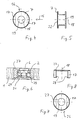
- FIG. 1 shows a top view of a wall panel 1 introduced clamping device 2, of which only the clamping hook 3 protrude beyond the front wall panel edge 24.
- the reference symbol 14 is a profiled rod in which the clamp hooks 3 are releasably hooked.
- the clamping device 2 is in a milling marked with the reference number 5 embedded in the wall plate 1.
- the structure of the clamping device 2 can be found in WO 97/25536.
- An essential one Characteristic of the clamping device 2 is the head 6, which against the Effect of a spring force in the body of the clamping device 2 sunk and then inserted through the milling 5 into the wall plate 1 becomes. This head 6 then protrudes into a transverse bore in the Wall plate 1 into it, advantageously with the wall plate 1 is flush.
- Reference number 7 denotes the sleeve, its function is explained in connection with the other drawings.
- Fig. 2 shows a cross section along the line II-II of Fig. 1, wherein the same features with the same reference numerals Marked are. It can be clearly seen that the Clamping device 2 is pushed into the cutout 5 and that the head 6 of the clamping device 2 is flush with the surface 8 closes the wall plate 1, with a cylindrical around the axis 9 Bore 10 is provided in the before insertion of the Clamping device 2, the sleeve 7 is to be used.
- FIG. 3 is a cross section along the line III-III 1 shown.
- 4 shows the sleeve 7 in one Top view. 5, which is the same sleeve 7 in the side view from the direction 15 shows.
- the cylindrical sleeve 7 via a penetrating here has rectangular bore 16 on both sides in each case in plan view a circular section 17 of material left to stand for.
- Through the bore 16 is the body of the clamping device 2 can be pushed forward.
- Concentric to the axis of symmetry 18 of the cylinder of the sleeve 7, a receiving bore 19 is provided, whose diameter is adjusted so that the head 6 of the Clamping device 2 essentially fits into it.
- FIGS. 1 to 3 From the representation of the sleeve 7, its mode of operation is related with FIGS. 1 to 3 immediately clear.
- the force absorption in one of the directions of the double arrow 20 in FIG. 1 or 3 is through the large side surfaces of the clamping device 2 guaranteed.
- This force usually corresponds the weight of the wall panels 1, which via the clamping device 2 to be attached to profiled rods 14.
- the inventive sleeve to a clamping device also for trays / shelves and base plates or others are used for supporting areal elements, and here especially in exhibition stand construction.
- the area is greatly increased, about which forces can be absorbed, which in one of the Directions of the double arrow 12 act, i.e. essentially Tensile forces that remove the wall plate 1 from the profiled rod could into which the clamping hook 3 of the clamping device 2nd intervention.
- the stressed area of the sleeve 7 corresponds to train in the projection in Fig. 4 of the area in the Level of arrow 15 is arranged. This has thus the design chosen in the exemplary embodiment more than doubled.
- this area which is indicated in FIG. 14 by the reference symbol 11 is marked, also occur and in particular the surface areas identified by reference numeral 31 of the circular segment sections 17 in the jacket.
- the base 22 of the sleeve 7 is an abutment, which a Tilting of the head 6 in the sleeve 7 or of the sleeve 7 with respect the wall plate 1 safely prevented.
- the wall plate 1 a Retains bottom portion 21 so that the sleeve 27 only from the Top, i.e. only recognizable from one side in the wall plate is.
- FIGS. 7 and 8 in the representation of the sleeve 27 can be seen, it now has its recess 26 no longer via a base plate 22, but via two elongated ones Undercuts 28 in the corresponding in the clamping device Engage 2 grooves 29 provided.
- FIG. 9 shows a third embodiment of the invention, in which the height of the sleeve 37 provided here is reduced once again so that the undercuts 38 approximate half the height of the clamping device 2 in a corresponding provided groove 39 of this engage.
- the hole is too here formed into a U-shaped recess 26.
- 10 and 11 to see that the enlargement of the The effective area can also be guaranteed with a very low overall height of the sleeve is.
- the sleeve 7 not cylindrical, but angular, especially rectangular. Besides one Rectangle can also use other polygons for the outer shape of the sleeve to get voted. 12 gives a corresponding sketch reflected in the top view.
- This sleeve 47 can correspond to the first mentioned exemplary embodiments have different heights, through the plate 1 completely or undercuts exhibit. It is important in any case that a front Edge surface 48, which is perpendicular to the direction of arrow 12 lying surface larger than the diameter of the bore 49 through which the head 6 of the clamping device 2 protrudes. With the reference numeral 50 is in the sleeve 47 for the clamping device 2 designated bore designated.
- the Sleeve 47 of course requires the provision of one accordingly opening drilled at right angles in the wall plate 1.
- the lateral areas 48 which consist of a profile piece 1 Record the tractive force and use the control button 6 in the Introduce the clamping device 2 and then into the profiled rod 14.
- the head 6 is also like a honeycomb structure or an octagon possible.
- the hole 49 for the head 6 to the requirements of this one other head 6 having an outer shape can be adapted, whereby to fix the clamping device 2 and the clamping hook 3rd in a profiled rod 1, of course, the circular shape of the head 6 is preferred because it is thus easy to turn.
- FIG. 13 shows a perspective view of one with a Sleeve 7 according to the invention equipped clamping device 2, which is inserted in a wall plate 1, in front of a profiled Rod 14. The front rests after assembly 24 of the plate 1 on the profiled rod 14.
- FIGS. 1 and 13 shows a perspective view of the clamping device 2 with closure sleeve 7 according to FIGS. 1 and 13 in assembled Status.
- areas 11 and 31 can be recognized that protrude laterally beyond the clamping device 2 and thus after installation in the material of the wall plate 1 rest and are suitable for force absorption.
- clamping device 15 shows an exploded view of clamping device 2, Closure sleeve 7 and wall plate 1 according to FIG. 1 before assembly.
- the through bore 10 and the milling 5 can be seen in which the closure sleeve 7 in this order and the clamping device 2 are used.
- any clamping device can be a cuboid shape like the clamping device 2 Has.
- the clamping device can also be, for example have cylindrical body.
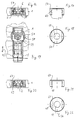
- FIG. 16 shows a cross section corresponding to FIG. 3 Wall plate 1, clamping device 2 and a sleeve 57 according to one fifth embodiment of the invention.
- the Clamping device 2 laterally each over the outer edge of the Housing of the clamping device 2 overlooking sections 58, the better in the partially cut top view of the clamping device 2 can be seen in FIG. 19.
- These sections 58 are part of the longitudinally movable slide 59.
- FIG. 17 shows a side view of the sleeve 57
- FIG. 18 shows a plan view of this sleeve 57. that laterally at the appropriate height and complementary to the sections 58 longitudinal grooves 60 are provided, which function as Undercuts 28 and 38 meet.
- the height is preferred the sleeve 57 thus as high as the height of the clamping device 2 with head 6.
- FIG Surface directed in the pull-in or pull-out direction 12 with the reference symbol 51 provided.
- FIG. 20 shows a cross section corresponding to FIG. 3 through wall plate 1, clamping device 2 and sleeve 67 according to one sixth embodiment of the invention
- FIG. 21 being a Side view
- Fig. 22 is a plan view of the sleeve 67 to Figure 20 illustrates.
- the clamping device 2 has rounded Side edges and in particular rounded lower side edges 69 on. These act together with undercuts 68 of the sleeve 67, which have the same complementary radius of curvature.
- FIG. 23 shows an exploded view of a clamping device 2 with a lock housing 92, a thin wall plate 91 and a closure sleeve 77 according to a seventh embodiment.
- the sleeve 77 is like the sleeve 57 with a groove 60 provided with protruding elements 58 of the clamping device 2 interact.
- a lock housing 92 is provided, which has a continuous cavity 93 with grooves 94 for which has elements 58.
- opening 95 is provided for receiving the sleeve 77.
- the complementary Form in the wall plate 91 is excluded. You can the mass of the closure housing 92 in another embodiment also be chosen so that the circular segment Recess 99 in the wall plate 91 is dispensed with.
- FIG. 24 finally shows an exploded view of one Clamping device 2 with a further closure housing 92, one thin wall plate 91 and a closure sleeve 87 according to one eighth embodiment.
- This embodiment is very similar to that from Fig. 23. The differences lie in that the sleeve 87 has two sections 84 and 85 with different Circle diameters. The back or the bottom Section 84 is smaller and forms part of the surface the groove 98. The upper larger section 85 takes a place in Lock housing 92, which in the lock housing 92 after 23 has been filled in by the latter itself. So that's one space-saving design of the clamping device 2 with the sleeve 87 possible for the thin wall plate 91.
- the sleeves intended for use with the closure housing 92 77 and 87 can of course also correspond to other embodiments and in particular according to the sleeves 7, 27, 37, 47, 57 and 67. Then in particular on the Groove 94 can be dispensed with if the clamping device 2 has none has protruding sections 58.
- the sleeves 7, 27, 37, 47, 57, 67, 77 and 87 and the sealing sleeve 92 preferably consist of a light metal, e.g. Aluminum. But you can also use any other material be made, especially from plastic. In summary these sleeves have the advantage that with such a closure sleeve 7, 27, 37, 47, 57, 67, 77 and 87 Clamping devices 2 considerably better in the longitudinal direction 12 of the Resist clamping device 2 acting tensile forces. With that Clamping devices 2 of the type mentioned now also with other materials the profile pieces 1, e.g. Wood, can be used. Through commitment a closure sleeve 92 can now also very thin profile elements 1, such as thin wooden panels 91, are used come.
- a closure sleeve 92 can now also very thin profile elements 1, such as thin wooden panels 91, are used come.
Abstract
Description
Die vorliegende Erfindung betrifft eine Vorrichtung zum lösbaren Verbinden zweier Profilstücke mit einer Klemmvorrichtung, die in eine in einem Profilstück vorgesehene Öffnung einführbar ist, mit einer Verschlusshülse, die zur formschlüssigen Aufnahme des Körpers der Klemmvorrichtung über eine Ausnehmung verfügt, und mit einem Bedienknopf, mit dem die Klemmvorrichtung in der Verschlusshülse arretierbar ist.The present invention relates to a device for detachable Connecting two profile pieces with a clamping device that in an opening provided in a profile piece can be inserted with a closure sleeve, which is used for the positive reception of the body the clamping device has a recess, and with an operating button with which the clamping device in the closure sleeve can be locked.
Eine solche Vorrichtung ist aus der DE 28 04 222 bekannt, in der ein Verbindungsbeschlag für Möbelteile beschrieben ist, mit der ein in einem Profilstück eingelassener Spannzapfen durch eine Verschlusshülse arretiert wird, wobei durch eine Drehung der Verschlusshülse eine Eingriffsspirale derselben in Ringnuten des Spannzapfens eingreift.Such a device is known from DE 28 04 222, in which a connection fitting for furniture parts is described with which a clamping pin embedded in a profile piece through a locking sleeve is locked, with a rotation of the closure sleeve an engagement spiral of the same in annular grooves of the Clamping pin engages.
Eine weitere Vorrichtung zur lösbaren Verbindung von zwei oder
mehr Holzteilen ist aus der DE 18 11 743 bekannt, bei der ein Metallzapfen
als Zugstange über eine als Kurvenscheibe ausgestaltete
Verschlusshülse lösbar in einem Profilstück arretiert wird.Another device for the detachable connection of two or
more wooden parts is known from
Die genannten Vorrichtungen sind für einen vielmaligen Auf- und Abbau, wie er im Messebau notwendig ist, nicht geeignet.The devices mentioned are for a multiple opening and closing Dismantling, as is necessary in exhibition stand construction, is not suitable.
Eine Klemmvorrichtung der oben genannten Art für den Messebau ist beispielsweise aus der WO 97/25536 der Anmelderin bekannt. Solche Klemmvorrichtungen sind dafür vorgesehen, zwei Profilstücke miteinander zu verbinden. Dabei handelt es sich zum einen üblicherweise um eine profilierte Stange, an welche ein Wandprofil angesetzt wird. In dem Wandprofil ist seitlich für jede Klemmvorrichtung eine innere Ausfräsung vorgesehen, in die die Klemmvorrichtung bis zu den überstehenden Hakenelementen eingeschoben werden kann. Auf der einen Seite der Wandoberfläche ist für eine aus der WO 97/25536 bekannten Klemmvorrichtung eine runde Bohrung vorgesehen, durch welche sich der Verriegelungskopf hindurcherstreckt, nachdem er gegen die Wirkung einer Federkraft in der Klemmvorrichtung versenkt durch die Ausfräsung bis zur Bohrung vorgeschoben worden ist, in welche er einrastet.A clamping device of the type mentioned above is for stand construction known for example from WO 97/25536 by the applicant. Such Clamping devices are provided for two profile pieces with each other connect to. On the one hand, this is usually the case around a profiled rod to which a wall profile is attached becomes. In the wall profile is laterally for each clamping device an internal milling is provided in which the clamping device can be inserted up to the protruding hook elements can. On one side of the wall surface is for one out of the Known clamping device WO 97/25536 provided a round bore, through which the locking head extends, after opposing the action of a spring force in the clamp countersunk through the cut to the hole into which it snaps into place.
Neben den Vorrichtungen der obengenannten Art sind aus dem Stand der Technik eine Reihe weiterer Vorrichtungen bekannt, die alle die beiden Merkmale aufweisen, dass sie in einer Ausfräsung der Wandplatte vorgeschoben werden und dass ein Bedienknopf zumindest auf der einen Seite der Wandplatte aus dieser - zumeist bündig - herausragt.In addition to the devices of the type mentioned above are from the prior art the art a number of other devices known, all the two features show that they are milled in Wall plate are advanced and that at least one control button on one side of the wall plate from this - mostly flush - protrudes.
Der besagte Bedienknopf nimmt zugleich Zugkräfte auf, die auf die Wandplatte einwirken und diese von der Profilleiste zu trennen versuchen.Said control button also absorbs tensile forces acting on the Act on the wall plate and separate it from the profile strip to attempt.
Neben dem Werkstoff Metall treten als Wandelemente nun vermehrt auch andere Werkstoffe, wie z.B. Holz, in Erscheinung. Dabei hat sich herausgestellt, dass der bei den bekannten Klemmvorrichtungen in die Wandfläche hineinragende Bedienknopf nicht geeignet ist, grössere Zugkräfte der oben beschriebenen Art aufzunehmen. Die selben Probleme treten bei Bodenplatten oder Tablare/Regalböden auf, die ebenfalls vermehrt aus Holz gefertigt werden.In addition to metal, there are now increasing numbers of wall elements other materials, such as Wood, in appearance. Doing it turned out that in the known clamping devices control button protruding into the wall surface is not suitable, absorb greater tensile forces of the type described above. The The same problems occur with floor plates or trays / shelves which are also increasingly made from wood.
Ausgehend von dem obengenannten Stand der Technik liegt der Erfindung daher die Aufgabe zugrunde, Vorrichtungen der eingangs genannten Art so auszugestalten, dass sie im Messebau für den häufigen Auf- und Abbau geeignet sind und zugleich auch mit nichtmetallischen Werkstoffen, wie z.B. Holz, eingesetzt werden können.The invention is based on the above-mentioned prior art therefore the task is based on devices of the aforementioned Art so that they can be used for frequent Construction and dismantling are suitable and at the same time with non-metallic Materials such as Wood, can be used.
Diese Aufgabe wird bei einer Vorrichtung der eingangs genannten Art erfindungsgemäss dadurch gelöst, dass der Bedienknopf in der Klemmvorrichtung vorgesehen ist, dass die Verschlusshülse eine den Bedienknopf aufnehmbare Bohrung aufweist, und dass der Bedienknopf in Querrichtung zur Längsachse der Klemmvorrichtung gegen eine Federkraft in den Körper der Klemmvorrichtung einschiebbar ist. This object is achieved in a device of the type mentioned Art solved according to the invention in that the control button in the Clamping device is provided that the closure sleeve a Has control button receptacle hole, and that the control button in the transverse direction to the longitudinal axis of the clamping device against a spring force can be inserted into the body of the clamping device.
Weitere vorteilhafte Ausgestaltungen der Erfindung sind in den abhängigen Ansprüchen angegeben.Further advantageous embodiments of the invention are in the dependent Claims specified.
Die Erfindung wird nun nachfolgend beispielhaft anhand der beigefügten Zeichnungen in verschiedenen Ausführungsbeispielen näher erläutert. Es zeigen:
- Fig. 1
- eine in eine Wandplatte eingeführte Klemmvorrichtung mit einer erfindungsgemässen Hülse in einer Draufsicht gemäss einem ersten Ausführungsbeispiel,
- Fig. 2
- die Wandplatte, Klemmvorrichtung und Hülse nach Fig. 1 in einem Querschnitt entlang der Linie II-II,
- Fig. 3
- dieselben Elemente nach Fig. 1 in einem Querschnitt entlang der Linie III-III,
- Fig. 4
- eine Draufsicht auf eine Hülse, wie sie im ersten Ausführungsbeispiel nach Fig. 1 bis 3 verwendet wird,
- Fig. 5
- eine Seitenansicht der Hülse nach Fig. 4,
- Fig. 6
- ein Fig. 3 entsprechender Querschnitt durch Wandplatte, Klemmvorrichtung und Hülse gemäss einem zweiten Ausführungsbeispiel der Erfindung,
- Fig. 7
- eine Draufsicht auf eine Hülse gemäss dem zweiten Ausführungsbeispiel,
- Fig. 8
- eine Seitenansicht der Hülse nach Fig. 7,
- Fig. 9
- ein Fig. 3 entsprechender Querschnitt durch Wandplatte, Klemmvorrichtung und Hülse gemäss einem dritten Ausführungsbeispiel der Erfindung,
- Fig. 10
- eine Draufsicht auf eine Hülse gemass dem dritten Ausführungsbeispiel,
- Fig. 11
- eine Seitenansicht der Hülse nach Fig. 10,
- Fig. 12
- eine Draufsicht auf eine Hülse gemäss einem vierten Ausführungsbeispiel der Erfindung,
- Fig. 13
- eine perspektivische Ansicht einer mit einer Hülse gemäss der Erfindung ausgestatteten Wandplatte mit einer profilierten Stange,
- Fig. 14
- eine perspektivische Ansicht der Klemmvorrichtung mit Verschlusshülse nach Fig. 1,
- Fig. 15
- eine Explosionsansicht von Klemmvorrichtung, Verschlusshülse und Wandplatte nach Fig. 1,
- Fig. 16
- ein Fig. 3 entsprechender Querschnitt durch Wandplatte, Klemmvorrichtung und Hülse gemäss einem fünften Ausführungsbeispiel der Erfindung,
- Fig. 17
- eine Seitenansicht einer Hülse gemass dem fünften Ausführungsbeispiei,
- Fig. 18
- eine Draufsicht auf die Hülse nach Fig. 16,
- Fig. 19
- die Klemmvorrichtung mit der erfindungsgemässen Hülse nach Fig. 16 in einer teilweise geschnittenen Draufsicht,
- Fig. 20
- ein Fig. 3 entsprechender Querschnitt durch Wandplatte, Klemmvorrichtung und Hülse gemäss einem sechsten Ausführungsbeispiel der Erfindung,
- Fig. 21
- eine Seitenansicht einer Hülse gemäss dem sechsten Ausführungsbeispiel,
- Fig. 22
- eine Draufsicht auf die Hülse nach Fig. 20,
- Fig. 23
- eine Explosionsansicht von Klemmvorrichtung mit einem Verschlussgehäuse, einer dünnen Wandplatte und einer Verschlusshülse gemäss einem siebten Ausführungsbeispiel, und
- Fig. 24
- eine Explosionsansicht von Klemmvorrichtung mit einem Verschlussgehäuse, einer dünnen Wandplatte und einer Verschlusshülse gemäss einem achten Ausführungsbeispiel.
- Fig. 1
- a clamping device inserted into a wall plate with a sleeve according to the invention in a plan view according to a first embodiment,
- Fig. 2
- the wall plate, clamping device and sleeve of FIG. 1 in a cross section along the line II-II,
- Fig. 3
- 1 in a cross section along the line III-III,
- Fig. 4
- 2 shows a plan view of a sleeve as used in the first exemplary embodiment according to FIGS. 1 to 3,
- Fig. 5
- 3 shows a side view of the sleeve according to FIG. 4,
- Fig. 6
- 3 corresponding cross section through wall plate, clamping device and sleeve according to a second embodiment of the invention,
- Fig. 7
- a plan view of a sleeve according to the second embodiment,
- Fig. 8
- 7 shows a side view of the sleeve according to FIG. 7,
- Fig. 9
- 3 corresponding cross section through wall plate, clamping device and sleeve according to a third embodiment of the invention,
- Fig. 10
- a plan view of a sleeve according to the third embodiment,
- Fig. 11
- 10 shows a side view of the sleeve according to FIG. 10,
- Fig. 12
- 3 shows a plan view of a sleeve according to a fourth exemplary embodiment of the invention,
- Fig. 13
- 2 shows a perspective view of a wall plate equipped with a sleeve according to the invention with a profiled rod,
- Fig. 14
- 2 shows a perspective view of the clamping device with the closure sleeve according to FIG. 1,
- Fig. 15
- 2 shows an exploded view of the clamping device, sealing sleeve and wall plate according to FIG. 1,
- Fig. 16
- 3 corresponding cross section through wall plate, clamping device and sleeve according to a fifth embodiment of the invention,
- Fig. 17
- a side view of a sleeve according to the fifth exemplary embodiment,
- Fig. 18
- 16 shows a plan view of the sleeve according to FIG. 16,
- Fig. 19
- 16 the clamping device with the sleeve according to the invention according to FIG. 16 in a partially sectioned top view,
- Fig. 20
- 3 corresponding cross section through wall plate, clamping device and sleeve according to a sixth embodiment of the invention,
- Fig. 21
- a side view of a sleeve according to the sixth embodiment,
- Fig. 22
- 20 shows a plan view of the sleeve according to FIG. 20,
- Fig. 23
- an exploded view of the clamping device with a closure housing, a thin wall plate and a closure sleeve according to a seventh embodiment, and
- Fig. 24
- an exploded view of the clamping device with a closure housing, a thin wall plate and a closure sleeve according to an eighth embodiment.
Die Fig. 1 zeigt in einer Draufsicht eine in eine Wandplatte 1
eingeführte Klemmvorrichtung 2, von der lediglich die Klemmhaken
3 über die vordere Wandplattenkante 24 überstehen. Mit dem Bezugszeichen
14 ist eine profilierte Stange bezeichnet, in welcher
die Klemmhaken 3 lösbar verhakbar sind. Die Klemmvorrichtung
2 ist in eine mit dem Bezugszeichen 5 gekennzeichnete Ausfräsung
in der Wandplatte 1 eingelassen. Der Aufbau der Klemmvorrichtung
2 ist der WO 97/25536 zu entnehmen. Ein wesentliches
Merkmal der Klemmvorrichtung 2 ist der Kopf 6, der gegen die
Wirkung einer Federkraft in den Korpus der Klemmvorrichtung 2
versenkt und dann durch die Fräsung 5 in die Wandplatte 1 eingeführt
wird. Dieser Kopf 6 ragt dann in einer Querbohrung in die
Wandplatte 1 hinein, wobei er vorteilhafterweise mit der Wandplatte
1 bündig abschliesst.1 shows a top view of a
Mit dem Bezugszeichen 7 ist die Hülse bezeichnet, deren Funktion
im Zusammenhang mit den weiteren Zeichnungen erläutert wird.
Die Fig. 2 zeigt einen Querschnitt entlang der Linie II-II der
Fig. 1, wobei jeweils gleiche Merkmale mit den gleichen Bezugszeichen
gekennzeichnet sind. Deutlich ist zu erkennen, dass die
Klemmvorrichtung 2 in die Ausfräsung 5 vorgeschoben ist und dass
der Kopf 6 der Klemmvorrichtung 2 bündig mit der Oberfläche 8
der Wandplatte 1 abschliesst, wobei um die Achse 9 eine zylindrische
Bohrung 10 vorgesehen ist, in die vor Einsetzen der
Klemmvorrichtung 2 die Hülse 7 einzusetzen ist.Fig. 2 shows a cross section along the line II-II of
Fig. 1, wherein the same features with the same reference numerals
Marked are. It can be clearly seen that the
Es ist gut zu erkennen, dass die Hülse 7 in dem Bereich der
Wandplatte 1 in dieser formschlüssig sitzt und insbesondere in
den mit 11 gekennzeichneten Bereichen Kräfte aufzunehmen vermag,
die in einer der Richtungen des Doppelpfeiles 12 wirken.It can be clearly seen that the
In der Fig. 3 ist ein Querschnitt entlang der Linie III-III aus
der Fig. 1 dargestellt. Die Fig. 4 zeigt die Hülse 7 in einer
Draufsicht. Zugehörig ist die Fig. 5, die dieselbe Hülse 7 in
der Seitenansicht aus der Richtung 15 zeigt. Es ist deutlich zu
erkennen, dass die zylindrische Hülse 7 über eine sie durchstossende,
hier rechteckige Bohrung 16 verfügt, die an beiden Seiten
jeweils in der Draufsicht einen Kreisabschnitt 17 an Material
stehenlässt. Durch die Bohrung 16 ist der Körper der Klemmvorrichtung
2 vorschiebbar. Konzentrisch zur Symmetrieachse 18
des Zylinders der Hülse 7 ist eine Aufnahmebohrung 19 vorgesehen,
deren Durchmesser so angepasst ist, dass der Kopf 6 der
Klemmvorrichtung 2 im wesentlichen formschlussig hineinpasst.3 is a cross section along the line III-
Aus der Darstellung der Hülse 7 wird deren Wirkungsweise im Zusammenhang
mit den Fig. 1 bis 3 sofort klar. Die Kraftaufnahme
in einer der Richtungen des Doppelpfeiles 20 in der Fig. 1
oder 3 wird durch die grossen Seitenflächen der Klemmvorrichtung
2 gewährleistet. Diese Krafteinwirkung entspricht zumeist
dem Gewicht der Wandplatten 1, die über die Klemmvorrichtung 2
an profilierten Stangen 14 befestigt werden. Neben den Wandplatten
1 kann die erfindungsgemässe Hülse zu einer Klemmvorrichtung
ebenfalls bei Tablaren/Regalböden und Bodenplatten oder anderen
zu tragenden flächenhaften Elementen zur Anwendung kommen, und
hier insbesondere im Messebau. From the representation of the
Durch den Einsatz der Hülse 7 ist die Fläche stark vergrössert,
über welche Kräfte aufgenommen werden können, die in einer der
Richtungen des Doppelpfeiles 12 wirken, d.h. im wesentlichen
Zugkräfte, die die Wandplatte 1 von der profilierten Stange entfernen
könnten, in die die Klemmhaken 3 der Klemmvorrichtung 2
eingreifen. Die auf Zug beanspruchte Flache der Hülse 7 entspricht
in der Projektion in der Fig. 4 der Fläche, die in der
Ebene des Pfeiles 15 angeordnet ist. Diese hat sich somit bei
der im Ausführungsbeispiel gewählten Auslegung mehr als verdoppelt.
Neben dieser Fläche, die in Fig. 14 durch das Bezugszeichen
11 gekennzeichnet ist, treten ebenfalls und insbesondere
die mit dem Bezugszeichen 31 gekennzeichneten Flächenbereiche
der Kreissegmentabschnitte 17 im Mantel hinzu. Gleichzeitig bildet
die Grundfläche 22 der Hülse 7 ein Widerlager, welches ein
Verkippen von dem Kopf 6 in der Hülse 7 bzw. von der Hülse 7 bezüglich
der Wandplatte 1 sicher verhindert.By using the
Natürlich ist die Wirkung der Hülse ebenfalls mit anders ausgestalteten
Klemmvorrichtungen oder Hülsen realisierbar. Insbesondere
kann es wünschenswert sein, dass, wie beim zweiten Ausführungsbeispiel
in der Fig. 6 dargestellt, die Wandplatte 1 einen
Bodenabschnitt 21 beibehält, so dass die Hülse 27 nur von der
Oberseite, d.h. nur von einer Seite, in der Wandplatte zu erkennen
ist. Wie aus den Fig. 7 und 8 bei der Darstellung der Hülse
27 zu erkennen ist, verfügt diese mit ihrer Ausnehmung 26 nun
nicht mehr über eine Bodenplatte 22, sondern über zwei längliche
Hinterschneidungen 28, die in entsprechend in der Klemmvorrichtung
2 vorgesehene Nuten 29 eingreifen.Of course, the effect of the sleeve is also different
Clamping devices or sleeves can be implemented. In particular
it may be desirable that, as in the
Die Fig. 9 zeigt ein drittes Ausführungsbeispiel der Erfindung,
bei dem die Höhe der hier vorgesehenen Hülse 37 noch einmal verringert
worden ist, so dass die Hinterschneidungen 38 in ungefähr
halber Höhe der Klemmvorrichtung 2 in eine entsprechend
vorgesehene Rille 39 von dieser eingreifen. Die Bohrung ist auch
hier zu einer U-förmigen Ausnehmung 26 umgebildet. Hier ist in
den Fig. 10 und 11 zu erkennen, dass die Vergrösserung der
Wirkfläche auch mit einer sehr geringen Bauhöhe der Hülse gewährleistbar
ist.9 shows a third embodiment of the invention,
in which the height of the
Neben den hier dargestellten Ausführungsbeispielen ist es naturlich
ebenso möglich, die Hülse 7 nicht zylindrisch, sondern ekkig,
insbesondere rechtwinklig, auszugestalten. Neben einem
Rechteck können für die äussere Form der Hülse auch andere Vielecke
gewählt werden. Die Fig. 12 gibt eine entsprechende Skizze
in der Draufsicht wider. Diese Hülse 47 kann entsprechend den
zuerst genannten Ausführungsbeispielen verschiedene Höhen haben,
durch die Platte 1 vollständig hindurchtreten oder Hinterschneidungen
aufweisen. Wichtig ist in jedem Fall, dass eine vordere
Kantenfläche 48 besteht, deren senkrecht zur Pfeilrichtung 12
liegende Oberfläche grösser als der Durchmesser der Bohrung 49
ist, durch die der Kopf 6 der Klemmvorrichtung 2 hindurchragt.
Mit dem Bezugszeichen 50 ist die in der Hülse 47 für die Klemmvorrichtung
2 vorgesehene Bohrung bezeichnet. Der Einsatz der
Hülse 47 erfordert natürlich das Vorsehen einer entsprechend
rechtwinklig ausgebohrten Öffnung in der Wandplatte 1. Vorteilhafterweise
bestehen neben der Bohrung 50 seitliche Wülste,
hier die seitlichen Bereiche 48, die die aus einem Profilstück 1
stammenden Zugkraft aufnehmen und über den Bedienknopf 6 in die
Klemmvorrichtung 2 und dann in die profilierte Stange 14 einleiten.In addition to the exemplary embodiments shown here, it is natural
also possible, the
Natürlich sind auch andere Formen des Kopfes 6, wie eine Wabenstruktur
oder ein Oktagon möglich. Insbesondere kann die Bohrung
49 für den Kopf 6 an die Erfordernisse dieses eventuell eine
andere äussere Form aufweisenden Kopfes 6 angepasst werden,
wobei zur Fixierung der Klemmvorrichtung 2 und der Klemmhaken 3
in einer profilierten Stange 1 natürlich die Kreisform des Kopfes
6 bevorzugt ist, da diese somit einfach zu drehen ist. Of course, other shapes of the
Die Fig. 13 zeigt eine perspektivische Ansicht einer mit einer
Hülse 7 gemäss der Erfindung ausgestatteten Klemmvorrichtung 2,
die in einer Wandplatte 1 eingeschoben ist, vor einer profilierten
Stange 14. Dabei ruht nach dem Zusammenbau die Vorderseite
24 der Platte 1 auf der profilierten Stange 14.13 shows a perspective view of one with a
Die Fig. 14 zeigt eine perspektivische Ansicht der Klemmvorrichtung
2 mit Verschlusshülse 7 nach Fig. 1 bzw. 13 in zusammengesetztem
Zustand. Insbesondere können die Bereiche 11 und 31 erkannt
werden, die seitlich über die Klemmvorrichtung 2 hinausstehen
und damit nach dem Einbau in dem Material der Wandplatte
1 ruhen und zur Kraftaufnahme geeignet sind.14 shows a perspective view of the
Die Fig. 15 zeigt eine Explosionsansicht von Klemmvorrichtung 2,
Verschlusshülse 7 und Wandplatte 1 nach Fig. 1 vor dem Zusammenbau.
Dabei sind die durchgehende Bohrung 10 und die Ausfräsung 5
zu erkennen, in die in dieser Reihenfolge die Verschlusshülse 7
und die Klemmvorrichtung 2 eingesetzt werden. Dabei ist festzustellen,
dass die Erfindung mit jeglicher Klemmvorrichtung eingesetzt
werden kann, die wie die Klemmvorrichtung 2 eine Quaderform
hat. Die Klemmvorrichtung kann aber beispielsweise auch einen
zylinderförmigen Körper aufweisen.15 shows an exploded view of
Die Fig. 16 zeigt einen Fig. 3 entsprechenden Querschnitt durch
Wandplatte 1, Klemmvorrichtung 2 und einer Hülse 57 gemäss einem
fünften Ausführungsbeispiel der Erfindung. Hier verfügt die
Klemmvorrichtung 2 seitlich jeweils über über den Aussenrand des
Gehäuses der Klemmvorrichtung 2 überscehende Abschnitte 58, die
besser in der teilweise geschnittenen Draufsicht auf die Klemmvorrichtung
2 nach der Fig. 19 zu erkennen sind. Diese Abschnitte
58 sind Bestandteil des längsbeweglichen Schiebers 59.FIG. 16 shows a cross section corresponding to FIG. 3
Die Fig. 17 zeigt eine Seitenansicht der Hülse 57 und die Fig.
18 eine Draufsicht auf diese Hülse 57. Dabei ist zu erkennen,
dass seitlich in entsprechender Höhe und komplementär zu den Abschnitten
58 Längsnuten 60 vorgesehen sind, die die Funktion der
Hinterschneidungen 28 bzw. 38 erfüllen. Vorzugsweise ist die Höhe
der Hülse 57 damit genauso hoch wie die Höhe der Klemmvorrichtung
2 mit Kopf 6. In der Seitenansicht der Fig. 17 ist die
in Ein- bzw. Auszugsrichtung 12 gerichtete Fläche mit dem Bezugszeichen
51 versehen.FIG. 17 shows a side view of the
Die Fig. 20 zeigt einen der Fig. 3 entsprechenden Querschnitt
durch Wandplatte 1, Klemmvorrichtung 2 und Hülse 67 gemäss einem
sechsten Ausführungsbeispiel der Erfindung, wobei Fig. 21 eine
Seitenansicht und Fig. 22 eine Draufsicht auf die Hülse 67 nach
Fig. 20 darstellt. Hier weist die Klemmvorrichtung 2 abgerundete
Seitenkanten und insbesondere abgerundete untere Seitenkanten 69
auf. Diese wirken zusammen mit Hinterschneidungen 68 der Hülse
67, die denselben komplementären Krümmungsradius aufweisen.FIG. 20 shows a cross section corresponding to FIG. 3
through
Die Fig. 23 zeigt eine Explosionsansicht von einer Klemmvorrichtung
2 mit einem Verschlussgehäuse 92, einer dünnen Wandplatte
91 und einer Verschlusshülse 77 gemäss einem siebten Ausführungsbeispiel.
Die Hülse 77 ist wie die Hülse 57 mit einer Nut
60 versehen, die mit überstehenden Elementen 58 der Klemmvorrichtung
2 zusammenwirken. Um die Klemmvorrichtung 2 auch bei
Wandplatten 91 einsetzen zu können, die dünner als die Klemmvorrichtung
2 selber sind, ist ein Verschlussgehäuse 92 vorgesehen,
welches einen durchgehenden Hohlraum 93 mit Nuten 94 für
die Elemente 58 aufweist. Ferner ist eine quer zur Richtung 12
angeordnete Öffnung 95 zur Aufnahme der Hülse 77 vorgesehen. Dabei
stehen Zylinderabschnitte 96 über die Aussenwände des Verschlussgehäuses
92 über. Zur Aufnahme der dünnen Wandplatte 91
ist auf den gegenüberliegenden Seiten des Verschlussgehäuses 92
jeweils eine längs verlaufende Nut 98 vorgesehen, deren komplementäre
Form in der Wandplatte 91 ausgenommen ist. Dabei können
die Masse des Verschlussgahäuses 92 in einer andere Ausführungsform
auch so gewählt werden, dass auf die kreisabschnittförmige
Ausnehmung 99 in der Wandplatte 91 verzichtet wird. 23 shows an exploded view of a
Die Fig. 24 schliesslich zeigt eine Explosionsansicht von einer
Klemmvorrichtung 2 mit einem weiteren Verschlussgehäuse 92, einer
dünnen Wandplatte 91 und einer Verschlusshülse 87 gemäss einem
achten Ausführungsbeispiel. Dieses Ausführungsbeispiel ist
sehr ähnlich zu dem aus der Fig. 23. Die Unterschiede liegen
darin, dass die Hülse 87 über zwei Abschnitte 84 und 85 mit unterschiedlichen
Kreisdurchmessern verfügt. Der hinter oder untere
Abschnitt 84 ist kleiner und bildet einen Teil der Oberfläche
der Nut 98. Der obere grössere Abschnitt 85 nimmt einen Platz im
Verschlussgehäuse 92 ein, der in dem Verschlussgehäuse 92 nach
Fig. 23 von diesem selbst ausgefüllt worden ist. Damit ist eine
platzsparende Bauweise der Klemmvorrichtung 2 mit der Hülse 87
für die dünne Wandplatte 91 möglich.24 finally shows an exploded view of one
Die zum Einsatz mit dem Verschlussgehäuse 92 vorgesehenen Hülsen
77 und 87 können natürlich auch entsprechend anderen Ausführungsformen
und insbesondere gemäss den Hülsen 7, 27, 37, 47, 57
und 67 ausgestaltet sein. Dann kann insbesondere auch auf die
Nut 94 verzichtet werden, wenn die Klemmvorrichtung 2 uber keine
überstehenden Abschnitte 58 verfügt.The sleeves intended for use with the
Die Hülsen 7, 27, 37, 47, 57, 67, 77 und 87 sowie die Verschlusshülse
92 bestehen vorzugsweise aus einem Leichtmetall,
z.B. Aluminium. Sie können aber auch aus jedem anderen Material
gefertigt sein, insbesondere aus Kunststoff. Zusammenfassend
weisen diese Hülsen den Vorteil auf, dass mit einer solchen Verschlusshülse
7, 27, 37, 47, 57, 67, 77 und 87 ausgestattete
Klemmeinrichtungen 2 erheblich besser in Längsrichtung 12 der
Klemmeinrichtung 2 wirkenden Zugkräften widerstehen. Damit sind
Klemmvorrichtungen 2 der besagten Art nun auch bei anderen Materialien
der Profilstücke 1, z.B. Holz, einsetzbar. Durch Einsatz
einer Verschlusshülse 92 können nun auch sehr dünne Profilelemente
1, wie beispielsweise dünne Holzplatten 91, zum Einsatz
kommen.The
Claims (9)
- Device for the releasable connection of two profile pieces (1, 91 and 14), having a clamping device (2) which can be introduced into an opening (5) provided in a profile piece (1, 91), having a closure sleeve (7, 27, 37, 47, 57, 67, 77, 87) which, for receiving the body of the clamping device (2) in a form-fitting manner, has a recess (16, 50), and having an operating knob by means of which the clamping device (2) can be secured in the closure sleeve (7, 27, 37, 47, 57, 67, 77, 87), characterised in that the operating knob (6) is provided in the clamping device (2), in that the closure sleeve (7, 27, 37, 47, 57, 67, 77, 87) has a bore (19) which receives the operating knob (6), and in that the operating knob (6) can be pushed into the body of the clamping device (2), counter to a spring force, in the transverse direction to the longitudinal axis of the clamping device (2).
- Device according to claim 1, characterised in that the closure sleeve (7, 27, 37, 57, 67) has the outer form of a cylinder.
- Device according to claim 1, characterised in that the closure sleeve (47) has the outer form of a polygon.
- Device according to one of claims 1 to 3, characterised in that the recess (16, 50) is a bore, with the result that the closure sleeve (7) has a base (22) located opposite the bore (19).
- Device according to one of claims 1 to 3, characterised in that the recess (26) is configured such that, of the closure sleeve (27, 37, 67), a cross-sectionally U-shaped part remains, and in that the closure sleeve (27, 37, 67) has undercuts (28, 38, 68) which interact with complementary grooves (29, 39, 69) of the clamping device (2).
- Device according to one of claims 1 to 3, characterised in that the closure sleeve (57, 77, 87) has grooves (60) which run laterally in the introduction direction (12) and interact with complementary sections (58) of the clamping device (2).
- Closure housing for a device according to one of the preceding claims, characterised in that the closure housing (92) has a cavity (93), for receiving the clamping device (2), an opening (95), which is aligned transversely to the longitudinal direction of said clamping device and is intended for receiving the closure sleeve (77, 87), and grooves (98), which run in the longitudinal direction on the narrow sides of the closure housing and are intended for receiving the profile pieces (91).
- Closure housing according to claim 7, characterised in that, on its narrow sides, it has projecting cylinder sections (96) which interact with complementary recesses (99) of the profile piece (91).
- Closure housing according to claim 7, characterised in that, on the narrow sides, the cavity (93) has mutually opposite grooves (94) for receiving sections (58) which project laterally beyond the clamping device (2).
Applications Claiming Priority (3)
| Application Number | Priority Date | Filing Date | Title |
|---|---|---|---|
| CH190097 | 1997-08-12 | ||
| CH190097 | 1997-08-12 | ||
| PCT/CH1998/000337 WO1999009326A1 (en) | 1997-08-12 | 1998-08-11 | Closing bushing for a clamping device used for removably connecting two profiled parts |
Publications (2)
| Publication Number | Publication Date |
|---|---|
| EP1003977A1 EP1003977A1 (en) | 2000-05-31 |
| EP1003977B1 true EP1003977B1 (en) | 2003-06-25 |
Family
ID=4221225
Family Applications (1)
| Application Number | Title | Priority Date | Filing Date |
|---|---|---|---|
| EP98936064A Expired - Lifetime EP1003977B1 (en) | 1997-08-12 | 1998-08-11 | Closing bushing for a clamping device used for removably connecting two profiled parts |
Country Status (10)
| Country | Link |
|---|---|
| US (1) | US6334732B1 (en) |
| EP (1) | EP1003977B1 (en) |
| CN (1) | CN1117219C (en) |
| AT (1) | ATE243814T1 (en) |
| AU (1) | AU736455B2 (en) |
| DE (1) | DE59808834D1 (en) |
| HK (1) | HK1025143A1 (en) |
| HU (1) | HU222223B1 (en) |
| RU (1) | RU2232307C2 (en) |
| WO (1) | WO1999009326A1 (en) |
Families Citing this family (11)
| Publication number | Priority date | Publication date | Assignee | Title |
|---|---|---|---|---|
| DE20103064U1 (en) * | 2001-02-21 | 2001-06-28 | Hestex Systems Bv | Clamp connector system |
| JP5132875B2 (en) * | 2005-10-07 | 2013-01-30 | ヘステックス システムズ ベー.フェー. | Clamp joint system |
| EP2006550A1 (en) * | 2007-06-23 | 2008-12-24 | Hestex Systems B.V. | Connecting device |
| EP2088332A1 (en) * | 2008-02-08 | 2009-08-12 | Hestex Systems B.V. | Connecting device |
| US8956071B2 (en) * | 2009-02-12 | 2015-02-17 | Moss Holding Company | Quick release joint system for assembling frames |
| DE202009010237U1 (en) * | 2009-07-28 | 2009-12-10 | Häfele GmbH & Co KG | Tray carrier and tray arrangement |
| EP2619463B1 (en) * | 2010-09-23 | 2014-11-19 | Syma Intercontinental AG | Slide plate for a cam-type closure |
| US8408835B1 (en) * | 2012-01-05 | 2013-04-02 | Zhijun Zhang | Clamp for section tubes with rigid hooked lever |
| EP2685111B1 (en) | 2012-07-09 | 2019-05-01 | Syma Intercontinental AG | Clamp piece for a detachable connection of two profile pieces |
| US9151060B2 (en) * | 2013-10-22 | 2015-10-06 | Stramos Oy | Construction block |
| US11619250B2 (en) * | 2021-04-23 | 2023-04-04 | Ming Yang Aluminum Co., Ltd. | Connecting apparatus |
Family Cites Families (16)
| Publication number | Priority date | Publication date | Assignee | Title |
|---|---|---|---|---|
| DE1429491B2 (en) * | 1964-09-29 | 1970-06-25 | Baresel-Bofinger, Rudolf, 7129 Hsfeld | Device for easily detachable connection of plate-shaped furniture parts by means of eccentric locks |
| LU57387A1 (en) * | 1968-11-25 | 1969-03-03 | ||
| DE2625182C3 (en) * | 1976-03-11 | 1980-06-19 | Richard Heinze Gmbh & Co Kg, 4900 Herford | Fitting for the detachable connection of two components, in particular panel-shaped components for furniture |
| DE2610200C3 (en) * | 1976-03-11 | 1980-01-31 | Richard Heinze Gmbh & Co Kg, 4900 Herford | Fitting for the detachable connection of two components, in particular panel-shaped components for furniture |
| DE2723850C2 (en) * | 1977-05-26 | 1986-08-28 | Richard Heinze GmbH & Co KG, 4905 Spenge | Furniture hinge |
| DE2804222A1 (en) * | 1978-02-01 | 1979-08-02 | Lautenschlaeger Kg Karl | Right-angle connector for furniture - has flanged pin screwed into one component tensioned by disc with surface spiral in other |
| US4787769A (en) * | 1984-03-19 | 1988-11-29 | Exibelco Gmbh | Connecting element |
| CN88200402U (en) * | 1988-01-22 | 1988-12-07 | 牛玉荣 | Metal boom coupling piece |
| EP0371153B1 (en) * | 1988-11-28 | 1992-05-13 | Exibelco GmbH | Connection device |
| DE59000537D1 (en) * | 1989-08-11 | 1993-01-14 | Vieler Gerd & Bernd Kg | BASE WITH A PROFILE ROD COUPLING CONNECTOR. |
| RU2089759C1 (en) * | 1991-03-25 | 1997-09-10 | Сима Интерконтиненталь, АГ | Clamping device for split connection of two shaped workpieces |
| DE4218842A1 (en) * | 1992-06-09 | 1993-12-16 | Offenbroich A | Clamping device |
| DE59305953D1 (en) * | 1992-11-21 | 1997-04-30 | Hestex Systems Bv | Fastener |
| GB2301412B (en) * | 1995-05-31 | 1999-03-10 | Titus Int Plc | A housing for joint forming devices |
| CZ293061B6 (en) * | 1996-01-09 | 2004-01-14 | Syma Intercontinental Ag | Clamping device for releasable securing two section parts |
| IT1298152B1 (en) * | 1998-01-19 | 1999-12-20 | Giovannetti F | FIXING DEVICE TO JOIN FURNITURE PANELS BETWEEN THEM |
-
1998
- 1998-08-11 AU AU85275/98A patent/AU736455B2/en not_active Ceased
- 1998-08-11 WO PCT/CH1998/000337 patent/WO1999009326A1/en active IP Right Grant
- 1998-08-11 CN CN98807905A patent/CN1117219C/en not_active Expired - Fee Related
- 1998-08-11 HU HU0002799A patent/HU222223B1/en not_active IP Right Cessation
- 1998-08-11 AT AT98936064T patent/ATE243814T1/en active
- 1998-08-11 US US09/462,874 patent/US6334732B1/en not_active Expired - Lifetime
- 1998-08-11 EP EP98936064A patent/EP1003977B1/en not_active Expired - Lifetime
- 1998-08-11 DE DE59808834T patent/DE59808834D1/en not_active Expired - Lifetime
- 1998-08-11 RU RU2000106037/11A patent/RU2232307C2/en not_active IP Right Cessation
-
2000
- 2000-07-11 HK HK00104246A patent/HK1025143A1/en not_active IP Right Cessation
Also Published As
| Publication number | Publication date |
|---|---|
| AU8527598A (en) | 1999-03-08 |
| CN1265725A (en) | 2000-09-06 |
| RU2232307C2 (en) | 2004-07-10 |
| WO1999009326A1 (en) | 1999-02-25 |
| DE59808834D1 (en) | 2003-07-31 |
| ATE243814T1 (en) | 2003-07-15 |
| US6334732B1 (en) | 2002-01-01 |
| HU222223B1 (en) | 2003-05-28 |
| HUP0002799A2 (en) | 2000-12-28 |
| AU736455B2 (en) | 2001-07-26 |
| HUP0002799A3 (en) | 2001-12-28 |
| HK1025143A1 (en) | 2000-11-03 |
| EP1003977A1 (en) | 2000-05-31 |
| CN1117219C (en) | 2003-08-06 |
Similar Documents
| Publication | Publication Date | Title |
|---|---|---|
| DE4125976C2 (en) | ||
| DE3200310A1 (en) | BASED FROM MULTIPLE PROFILE RODS | |
| DE202006021264U1 (en) | Door and window frame with an undercut engagement area for a gear unit | |
| WO1995022702A1 (en) | Connecting element threaded on both sides | |
| EP1003977B1 (en) | Closing bushing for a clamping device used for removably connecting two profiled parts | |
| EP0099972B1 (en) | Connecting element for slabs | |
| DE4306877C2 (en) | Profile bar system for frame structures, vehicle bodies, shelving systems, workshop and laboratory equipment or the like. | |
| DE4230230A1 (en) | Armrest for seating | |
| DE3603453C2 (en) | ||
| DE102005028573A1 (en) | Fastening arrangement for e.g. table cabinet part such as table leg, has insert part partially arranged within opening e.g. blind hole or passage opening, of plate, and support part assigned to connecting part | |
| DE10348264B3 (en) | Corner bracket for fixing back panels in grooved side walls and bases or tops of e.g. cupboards has arms at right angles to each other which have triangular blocks with diagonal screw holes on their outer ends | |
| DE202008000430U1 (en) | Net post with net hook | |
| DE2724201A1 (en) | FURNITURE CONSTRUCTION SYSTEM OR ASSEMBLY | |
| DE2059870A1 (en) | Dismountable furniture, e.g. Shelf, box, cupboard or the like. | |
| EP0898034B1 (en) | Hinge | |
| DE202005009719U1 (en) | Connection device for furniture, esp. for tables consists of support part and plate, insert fitted into the plate, and connection part with locking head | |
| DE102009057594B4 (en) | Fastening system for connecting a shelf with a support structure, shelf, shelving system and fastening device | |
| EP1070859B1 (en) | Fastening device with at least two profiled bars with grooves | |
| DE4316808C2 (en) | Clamping piece for pipe elements | |
| WO2001060203A1 (en) | Connecting element for a piece of furniture, in particular for a table | |
| DE2354066C3 (en) | Clamping device for attaching fittings to undercut longitudinal grooves having metal or plastic hollow profiles for window and door frames or the like. | |
| DE3232766C1 (en) | Frame comprising profile sections | |
| DE19701442C1 (en) | Screw union connecting first hollow profile to second profile at its end | |
| DE202021101966U1 (en) | Shelf for furniture | |
| AT396699B (en) | Junction element for connecting a plurality of beams |
Legal Events
| Date | Code | Title | Description |
|---|---|---|---|
| PUAI | Public reference made under article 153(3) epc to a published international application that has entered the european phase |
Free format text: ORIGINAL CODE: 0009012 |
|
| 17P | Request for examination filed |
Effective date: 19991227 |
|
| AK | Designated contracting states |
Kind code of ref document: A1 Designated state(s): AT CH DE GB IT LI SE |
|
| GRAH | Despatch of communication of intention to grant a patent |
Free format text: ORIGINAL CODE: EPIDOS IGRA |
|
| GRAH | Despatch of communication of intention to grant a patent |
Free format text: ORIGINAL CODE: EPIDOS IGRA |
|
| GRAA | (expected) grant |
Free format text: ORIGINAL CODE: 0009210 |
|
| AK | Designated contracting states |
Designated state(s): AT CH DE GB IT LI SE |
|
| REG | Reference to a national code |
Ref country code: GB Ref legal event code: FG4D Free format text: NOT ENGLISH |
|
| REG | Reference to a national code |
Ref country code: CH Ref legal event code: NV Representative=s name: ISLER & PEDRAZZINI AG Ref country code: CH Ref legal event code: EP |
|
| REF | Corresponds to: |
Ref document number: 59808834 Country of ref document: DE Date of ref document: 20030731 Kind code of ref document: P |
|
| GBT | Gb: translation of ep patent filed (gb section 77(6)(a)/1977) |
Effective date: 20030801 |
|
| REG | Reference to a national code |
Ref country code: SE Ref legal event code: TRGR |
|
| PLBE | No opposition filed within time limit |
Free format text: ORIGINAL CODE: 0009261 |
|
| STAA | Information on the status of an ep patent application or granted ep patent |
Free format text: STATUS: NO OPPOSITION FILED WITHIN TIME LIMIT |
|
| 26N | No opposition filed |
Effective date: 20040326 |
|
| REG | Reference to a national code |
Ref country code: CH Ref legal event code: PCAR Free format text: ISLER & PEDRAZZINI AG;POSTFACH 1772;8027 ZUERICH (CH) |
|
| PGFP | Annual fee paid to national office [announced via postgrant information from national office to epo] |
Ref country code: CH Payment date: 20110818 Year of fee payment: 14 |
|
| PGFP | Annual fee paid to national office [announced via postgrant information from national office to epo] |
Ref country code: SE Payment date: 20120821 Year of fee payment: 15 Ref country code: GB Payment date: 20120821 Year of fee payment: 15 |
|
| PGFP | Annual fee paid to national office [announced via postgrant information from national office to epo] |
Ref country code: IT Payment date: 20120823 Year of fee payment: 15 Ref country code: DE Payment date: 20120822 Year of fee payment: 15 |
|
| PGFP | Annual fee paid to national office [announced via postgrant information from national office to epo] |
Ref country code: AT Payment date: 20120813 Year of fee payment: 15 |
|
| REG | Reference to a national code |
Ref country code: CH Ref legal event code: PL |
|
| REG | Reference to a national code |
Ref country code: SE Ref legal event code: EUG |
|
| REG | Reference to a national code |
Ref country code: AT Ref legal event code: MM01 Ref document number: 243814 Country of ref document: AT Kind code of ref document: T Effective date: 20130811 |
|
| GBPC | Gb: european patent ceased through non-payment of renewal fee |
Effective date: 20130811 |
|
| PG25 | Lapsed in a contracting state [announced via postgrant information from national office to epo] |
Ref country code: CH Free format text: LAPSE BECAUSE OF NON-PAYMENT OF DUE FEES Effective date: 20130831 Ref country code: LI Free format text: LAPSE BECAUSE OF NON-PAYMENT OF DUE FEES Effective date: 20130831 Ref country code: SE Free format text: LAPSE BECAUSE OF NON-PAYMENT OF DUE FEES Effective date: 20130812 Ref country code: DE Free format text: LAPSE BECAUSE OF NON-PAYMENT OF DUE FEES Effective date: 20140301 |
|
| REG | Reference to a national code |
Ref country code: DE Ref legal event code: R119 Ref document number: 59808834 Country of ref document: DE Effective date: 20140301 |
|
| PG25 | Lapsed in a contracting state [announced via postgrant information from national office to epo] |
Ref country code: IT Free format text: LAPSE BECAUSE OF NON-PAYMENT OF DUE FEES Effective date: 20130811 Ref country code: AT Free format text: LAPSE BECAUSE OF NON-PAYMENT OF DUE FEES Effective date: 20130811 |
|
| PG25 | Lapsed in a contracting state [announced via postgrant information from national office to epo] |
Ref country code: GB Free format text: LAPSE BECAUSE OF NON-PAYMENT OF DUE FEES Effective date: 20130811 |