EP1003684B1 - Dispositif d'alimentation - Google Patents
Dispositif d'alimentation Download PDFInfo
- Publication number
- EP1003684B1 EP1003684B1 EP98948830A EP98948830A EP1003684B1 EP 1003684 B1 EP1003684 B1 EP 1003684B1 EP 98948830 A EP98948830 A EP 98948830A EP 98948830 A EP98948830 A EP 98948830A EP 1003684 B1 EP1003684 B1 EP 1003684B1
- Authority
- EP
- European Patent Office
- Prior art keywords
- conveyed
- conveyor belt
- feeding machine
- conveyor
- machine according
- Prior art date
- Legal status (The legal status is an assumption and is not a legal conclusion. Google has not performed a legal analysis and makes no representation as to the accuracy of the status listed.)
- Expired - Lifetime
Links
Images


Classifications
-
- B—PERFORMING OPERATIONS; TRANSPORTING
- B65—CONVEYING; PACKING; STORING; HANDLING THIN OR FILAMENTARY MATERIAL
- B65H—HANDLING THIN OR FILAMENTARY MATERIAL, e.g. SHEETS, WEBS, CABLES
- B65H5/00—Feeding articles separated from piles; Feeding articles to machines
- B65H5/02—Feeding articles separated from piles; Feeding articles to machines by belts or chains, e.g. between belts or chains
- B65H5/021—Feeding articles separated from piles; Feeding articles to machines by belts or chains, e.g. between belts or chains by belts
- B65H5/023—Feeding articles separated from piles; Feeding articles to machines by belts or chains, e.g. between belts or chains by belts between a pair of belts forming a transport nip
-
- B—PERFORMING OPERATIONS; TRANSPORTING
- B65—CONVEYING; PACKING; STORING; HANDLING THIN OR FILAMENTARY MATERIAL
- B65H—HANDLING THIN OR FILAMENTARY MATERIAL, e.g. SHEETS, WEBS, CABLES
- B65H1/00—Supports or magazines for piles from which articles are to be separated
-
- B—PERFORMING OPERATIONS; TRANSPORTING
- B65—CONVEYING; PACKING; STORING; HANDLING THIN OR FILAMENTARY MATERIAL
- B65H—HANDLING THIN OR FILAMENTARY MATERIAL, e.g. SHEETS, WEBS, CABLES
- B65H29/00—Delivering or advancing articles from machines; Advancing articles to or into piles
- B65H29/66—Advancing articles in overlapping streams
-
- B—PERFORMING OPERATIONS; TRANSPORTING
- B65—CONVEYING; PACKING; STORING; HANDLING THIN OR FILAMENTARY MATERIAL
- B65H—HANDLING THIN OR FILAMENTARY MATERIAL, e.g. SHEETS, WEBS, CABLES
- B65H3/00—Separating articles from piles
- B65H3/34—Article-retaining devices controlling the release of the articles to the separators
-
- B—PERFORMING OPERATIONS; TRANSPORTING
- B65—CONVEYING; PACKING; STORING; HANDLING THIN OR FILAMENTARY MATERIAL
- B65H—HANDLING THIN OR FILAMENTARY MATERIAL, e.g. SHEETS, WEBS, CABLES
- B65H5/00—Feeding articles separated from piles; Feeding articles to machines
- B65H5/02—Feeding articles separated from piles; Feeding articles to machines by belts or chains, e.g. between belts or chains
- B65H5/021—Feeding articles separated from piles; Feeding articles to machines by belts or chains, e.g. between belts or chains by belts
- B65H5/025—Feeding articles separated from piles; Feeding articles to machines by belts or chains, e.g. between belts or chains by belts between belts and rotary means, e.g. rollers, drums, cylinders or balls, forming a transport nip
-
- B—PERFORMING OPERATIONS; TRANSPORTING
- B65—CONVEYING; PACKING; STORING; HANDLING THIN OR FILAMENTARY MATERIAL
- B65H—HANDLING THIN OR FILAMENTARY MATERIAL, e.g. SHEETS, WEBS, CABLES
- B65H5/00—Feeding articles separated from piles; Feeding articles to machines
- B65H5/24—Feeding articles in overlapping streams, i.e. by separation of articles from a pile
-
- B—PERFORMING OPERATIONS; TRANSPORTING
- B65—CONVEYING; PACKING; STORING; HANDLING THIN OR FILAMENTARY MATERIAL
- B65H—HANDLING THIN OR FILAMENTARY MATERIAL, e.g. SHEETS, WEBS, CABLES
- B65H2404/00—Parts for transporting or guiding the handled material
- B65H2404/20—Belts
- B65H2404/26—Particular arrangement of belt, or belts
- B65H2404/261—Arrangement of belts, or belt(s) / roller(s) facing each other for forming a transport nip
Definitions
- the invention relates to a loading device for loading flat, flexible, in stacks entered goods, especially envelopes, in a station for further individual handling.
- Feeding devices are generally known, where the material to be conveyed is a stack of items to be conveyed entered into magazines from which the Items conveyed individually, for example by means of Suction rolls or grippers, pulled off and into a station be handed over for further, individual handling.
- U.S. Patent 5,161,792 shows one Feed channel of a feeder with in this conveyor channel arranged conveyor belts Movement of stacks from the edge Conveyed items in the direction of a discharge channel, in which opposing Conveyor belt units the individual pieces of conveyed goods convey scaled upwards.
- the object of the present invention is a loading device to give up flat, flexible material conveyed in stacks, especially from envelopes, in one station to another individual handling so that none strong limitation of the number of stacks entered Conveyed goods must be made and a Temporary storage of the conveyed items in one Magazine is avoided.
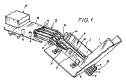
- the loading device of the here proposed type contains, as can be seen from Fig. 1 is an inclined downward Feed conveyor channel 1 for receiving stacks 2 of Conveyed goods 3, which in the from FIG. 2nd evident way placed in the feed channel 1 become.
- a discharge channel 4 leads from the lower end of the Feed channel 1 obliquely upwards.
- the slope of the Feed channel 1 is chosen to be large enough to be inside large stacks of items to be conveyed down into To let slip towards the discharge channel 4, but at the same time sufficiently low to the pressure of the Limit the stack to the lowest conveyed item.
- the feed channel 1 and the discharge channel 4 have a common right, seen in the direction of conveyance, angular side wall 5, a common, angular bottom 6 and a common one, in Direction of delivery seen left, angular side wall 7.
- the side wall 7 is attached to it on free leg with oblong holes in the angle 1 apparent in certain formats of the conveyed items in the direction transverse to the conveying direction adjustable.
- the bottom 6 of the feed channel 1 and Abinnekanals 4 is at the transition between the two Channels in the manner shown in FIG. 1 cut out such that the upper debris 8 out of three Conveyor belts 9 of a first conveyor belt unit 10 the bottom of the discharge channel 4 can be guided.
- the upper debris of the conveyor belts 9 thus follow that Course of the discharge channel 4 obliquely upwards and then go to the upper end of pulleys 11 supported in a horizontal course parallel to Level of a transfer table 12 above.
- the transfer table 12 is provided with longitudinal slots from which the Upper debris of the conveyor belts 9 in her horizontal section something about that Protrude table level.
- the lower debris of the conveyor belts 9 are over suitably positioned roles below the Transfer table 12 and below the floor of the Abddykanals 4 at the beginning of the conveyor near the transition between the feed channel and the discharge channel recycled.
- the first conveyor belt unit 10 Above the rubble 8 of the conveyor belts 9 the first conveyor belt unit 10 is a second Conveyor belt unit 13, the lower rubble of one Area before the change of direction of the upper rubble 8 to Horizontal run up to an area above the first Conveyor belt unit 10 in the horizontal section Opposite the first conveyor belt unit stand.
- This course of the conveyor belts 14 of the second Conveyor belt unit 13 is from FIGS. 1 and 2 without to recognize more. How symbolic by that Dashed line 15 indicated in Fig. 2, run the conveyor belts 9 of the first conveyor belt unit 10 and the conveyor belts 14 of the second conveyor belt unit 13 in sync. They are indicated by 16 in FIG indicated drive device put into circulation.
- the bottom of the discharge channel 4 is in one area between two conveyor belts 9 of the first Conveyor belt unit 10 with one in the conveying direction oriented cutout 17, from which something beyond the level of the bottom of the discharge channel 4 the upper run 18 of a circulating belt 19 (see Fig. 2) protrudes, the surface of which is low-friction.
- the circulating belt 19 is, as in Fig. 2 by the dash-dotted line 20 is indicated symbolically, synchronous and rectified to the conveyor belts 9 of the driven first conveyor belt unit 10.
- a stripper 21 acts as a counter surface, the training of which can be seen in detail from FIG. 3 is.
- a guide rail 22 is arranged, in which a Carriage 23 in a direction parallel to Delivery direction of the discharge channel 4 adjustable is held.
- the carriage 23 carries an arm 24 a wiper block 25, which in its lower part an approximately wedge-shaped wiper strip 26 made of rubber or plastic holds.
- the wiper strip 26 is a Pre-scraper 27 upstream.
- the distance of the bottom Edge of the wiper strip 26 from the surface of the Upper run 18 of the circulating belt 19 is by means of a setting knob 28 adjustable. Adjust by of the carriage 23 in the direction of the guide rail 22 can the position of the adjustment block 25 of the Scraper 21 to take into account the dimension of the Conveyed goods in the conveying direction along the upper run 18 of the circulating belt 19 can be set.
- the one with the upper run 18 of the circulating belt 19th as a counter surface interacting wipers 21 and Upper debris 8 of the conveyor belts 9 thus cause that between the conveyor belt units 10 and 13 scaled or staggered stream of Conveyed goods 3 arrives, the overlap distance or graduation distance on the stripper 21 is set.
- This scaled or staggered Stream of conveyed items 3 occurs on the output side between the conveyor belt units 10 and 13 on the Transfer table 12, which on a Tapping device 30 leads there in certain Distance from the output side of the first and second Conveyor belt unit is located and serves the front edge of the foremost conveyed item 3 to seize the scaled material flow and to subtract the piece of conveyed material in question in order to further handling or processing supply.
- the removal device 30 can in the Fig.
- FIG. 2 embodiment shown the shape of a Have conveyor chain 31, which from a drive 32nd is started cyclically as soon as one of the Conveyor chain 31 attached gripper 33 has captured the leading edge of a conveyed item 3.
- the upper claw of the gripper 33 is of spring means in the closed position against the lower gripper claw biased and will, as soon as the conveyor chain 31 Has gripper pliers 33 in the receiving position, by starting a cam of the upper gripper claw a cam 34 opened.
- Cam 34 can be closed by a drive 35 Gripper tongs are lowered.
- detectors for example Proximity detectors or light barriers report the respective operating position of the conveyor chain 31 and Gripper pliers 33.
- the conveyor chain 31 is located in that in FIG. 2 indicated operating position in which the gripper tongs 33 is receptive and open, one of them gives Drive or a resolver derived from the same Control signal from a control unit 36 a Request message via a control line 37 causes the drive 16 to the conveyor belt units 10th and 13 and the circulating belt 19 is put into operation and finally in the manner previously described the discharge side of the conveyor belt units 10 and 13 scaled flow of conveyed goods on the transfer table 12 exits.
- One following the detector 38 in the conveying direction second detector 39, which in turn from one in the Transfer table 12 mounted light barrier can be formed can then cause fine control of the drive 16 by the control unit 36 in such a way that the leading edge of the first conveyed item scaled material flow completely between the Gripper claws of the gripper tongs 33 is moved in and then through the upper gripper claw of the gripper tongs 33 Actuation of the cam plate 34 by means of the drive 35 is closed, after which the drive 32 is switched on is and the conveyor chain 31 to the first conveyed good its leading edge with reference to that in FIG. 2 shown position and position of the components subtracts to the left.
- the distance between that forming the detector 39 Light barrier and the bottom of the gripper 33 is so chosen that after the deduction of the first Piece of conveyed goods from the shingled flow of conveyed goods Light barrier or the detector 39 released again and for the fine positioning process of the then the first additional item to be conveyed is available. In any case, the distance mentioned is smaller than the minimum graduation distance or scaling distance of the conveyed items.
- the distance between the gripper 33 in the receiving position from the exit side of the gap between the Conveyor belt units 10 and 13 are selected so that a with its leading edge from the gripper 33 Conveyed piece of conveyed goods with its rear edge still held between the conveyor belt units 10 and 13 is.
- the removal device 30 and the transfer table 12 designed as a unit and on a trolley or carriage 40 movable in the conveying direction and adjustable so that the distance between the in Pickup position located gripper 33 and Output side of conveyor belt units 10 and 13 changed according to the format of the conveyed items can be.
- the roles to support the conveyor belts of the conveyor belt unit 13 are mounted on a common frame, the in turn around a horizontal one, to the bearing axes of the Rollers parallel axis can be pivoted such that the entire conveyor belt unit 13 for maintenance work or to eliminate interference from the Conveyor belt unit 10 is pivoted up.
- Relevant constructions familiar to the person skilled in the art as well as means for holding down the conveyed items in the area above the transfer table 12 are for Simplification of the representation in the drawing omitted.
- the removal device 30 can be operated according to the method shown in FIG. 4 shown modified embodiment also a Coupling pairs forming opposite one another Acceptance conveyor belts or rollers 41 and 42 contain the take-off conveyor rollers 42 by a drive 43 either lifted into a rest position or into one Conveying position against the acceptance conveyor belts 41 are lowerable. With this type of acceptance device 30, the conveyor belts 41 can run continuously.
- the upper run 18 of the revolving Volume 19 is a support and support surface for the Provide upper run 18, for example through part of the Soil 6 in that area of the upper run 18, about which way to set the format of the strippers 21 can be adjusted in the conveying direction of the belts 9.
- resolver output signals of the drive 32 for the conveyor chain 31 is determined when and via which Periods or drive section sections of the drive 16 for the conveyor belt units 10 and 13 in operation is set.
- Detectors 38 and 39 determine as Subordinate tax funds promoting the scaled material flow into the Gripper 33 or in the conveyor gap between the Conveyor belts 41 and the pressure rollers 42 (Fig. 4).
- Flaking or staggering is also a condition of To understand conveyed goods, in which these each other no longer overlap but already completely can be promoted individually to the transfer table 12.
Claims (11)
- Dispositif d'alimentation pour charger dans une station un produit à manutentionner plat, flexible introduit sous forme de piles et destiné à une manipulation individuelle ultérieure, comprenantcaractérisé en ce quea) un canal d'amenée (1) incliné vers le bas servant à recevoir la pile de produits à manutentionner (2),b) un canal d'évacuation (4) incliné conduisant vers le haut depuis l'extrémité inférieure du canal d'amenée, canal (4) sur le côté du fond duquel sont situés des premiers moyens de transport (10) présentant un frottement élevé avec le produit à manutentionner situé tout en bas de la pile et dont la direction de transport est inclinée vers le haut, et présentant, après un changement de direction, une direction de transport correspondant à la direction d'évacuation, dont l'inclinaison est réduite, présentant notamment une direction de transport horizontale ;c) des seconds moyens de transport (13) qui sont situés directement en face des premiers moyens de transport (10) dans une zone précédant le changement de direction et dans une zone d'inclinaison plus réduite de la direction de transport, notamment dans un segment horizontal ; etd) un dispositif d'individualisation (21) qui agit dans le canal d'évacuation (4), au-dessous de la zone du changement de direction, et qui sert à empiler par décalage le flux de produits à manutentionner transporté vers le haut depuis la pile (2) ;les premiers moyens de transport sont formés par des premières bandes transporteuses (9) dont les brins supérieurs (8) s'étendent de manière oblique vers le haut et, après le changement de direction mentionné, s'étendent avec une inclinaison réduite, notamment de manière horizontale, dans la direction d'évacuation ;les seconds moyens de transports sont formés par une seconde unité de bandes transporteuses (13) dont les brins inférieurs sont situés directement en face des brins supérieurs (8) des premières bandes transporteuses (9) mentionnées dans une zone précédant le changement de direction et jusqu'à une zone située au-dessus des premiers moyens de transport (10) dans le segment d'inclinaison réduite, notamment dans le segment horizontal ;le dispositif d'individualisation est formé par une racle (21) située dans le canal d'évacuation (4) et qui s'étend entre les deux premières bandes transporteuses (9) mentionnées, au-dessous de la zone du changement de direction, en direction d'une surface antagoniste (18) ;l'on prévoit un dispositif d'enlèvement (30) qui saisit le bord avant des produits individuels à manutentionner sur le côté de sortie des premières bandes transporteuses mentionnées et de la seconde unité de bandes transporteuses (10, 13), à une certaine distance de celles-ci, et qui tire ce bord de manière synchronisée ; etl'on prévoit un arrangement de détecteurs (38, 39) qui contient au moins un détecteur réagissant à l'arrivée du bord avant d'un produit à manutentionner (3) et qui, en fonction de cette réponse, commande l'actionnement du dispositif d'enlèvement (30) et/ou des premières bandes transporteuses mentionnées et de la seconde unité de bandes transporteuses (10, 13).
- Dispositif d'alimentation selon la revendication 1, caractérisé en ce que le canal d'amenée (1) et le canal d'évacuation (4) sont pourvus d'une paroi latérale (7) réglable par rapport à une partie de fond (6) respective afin de régler le format horizontal.
- Dispositif d'alimentation selon la revendication 1 ou 2, caractérisé en ce que la racle (21) peut être déplacée (22, 23, 24) parallèlement à la direction de transport des unités de bandes transporteuses (10, 13) afin de régler le format longitudinal.
- Dispositif d'alimentation selon l'une des revendications 1 à 3, caractérisé en ce que la racle est réglable (26, 28) perpendiculairement à la surface antagoniste (18) afin de régler le résultat de l'empilement par décalage.
- Dispositif d'alimentation selon l'une des revendications 1 à 4, caractérisé en ce que la racle coopère avec une bande (19) pourvue d'une surface à faible frottement qui forme la surface antagoniste et qui est entraínée dans le même sens que les bandes transporteuses des unités de bandes transporteuses (10, 13), laquelle bande (19) est située entre deux bandes transporteuses (9) de la première unité de bandes transporteuses (10).
- Dispositif d'alimentation selon l'une des revendications 1 à 5, caractérisé en ce que le dispositif d'enlèvement (30) comprend des paires de bandes transporteuses d'enlèvement (41) resp. rouleaux de pression (42) opposé(e)s qui forment une fente de transport et dont l'entraínement resp. la fonction de transport est commandée de manière synchronisée, notamment par l'arrangement de détecteurs (38, 39).
- Dispositif d'alimentation selon l'une des revendications 1 à 5, caractérisé en ce que le dispositif d'enlèvement (30) comprend une chaíne de manutention (31) munie de pinces (33) dont l'ouverture et la fermeture sont commandées de manière synchronisée.
- Dispositif d'alimentation selon l'une des revendications 1 à 7, caractérisé en ce que l'arrangement de détecteurs comprend deux détecteurs (38, 39) dont le premier est situé juste derrière le côté de sortie des première et seconde unités de bandes transporteuses (10, 13) dans le sens de transport et sert à produire un signal de détecteur utilisé pour le positionnement préalable du flux de produits à manutentionner empilés par décalage, et dont le second (39) est situé juste avant le dispositif d'enlèvement (30) à une distance de celui-ci qui est plus courte que la distance de décalage ou distance d'empilement par décalage minimale du flux de produits à manutentionner.
- Dispositif d'alimentation selon l'une des revendications 1 à 8, caractérisé en ce que le dispositif d'enlèvement (30) extrait les produits à manutentionner individuels du flux de produits à manutentionner empilés par décalage d'une manière synchronisée, le bord arrière du produit à manutentionner tiré se trouvant encore entre les bandes transporteuses des première et seconde unités de bandes transporteuses (10, 13).
- Dispositif d'alimentation selon la revendication 8 ou 9, caractérisé en ce que le signal de sortie du second détecteur (39) provoque l'entraínement de la première et de la seconde unité de bandes transporteuses (10, 13) en vue de l'exécution d'un trajet de transport mesuré du bord avant d'un produit à manutentionner depuis le second détecteur jusque dans la position de réception du dispositif d'enlèvement (30).
- Dispositif d'alimentation selon l'une des revendications 1 à 10, caractérisé en ce que la distance entre le dispositif d'enlèvement (30) et le côté de sortie des première et seconde unités de bandes transporteuses (10, 13) est réglable.
Applications Claiming Priority (3)
| Application Number | Priority Date | Filing Date | Title |
|---|---|---|---|
| DE19735382 | 1997-08-14 | ||
| DE19735382A DE19735382A1 (de) | 1997-08-14 | 1997-08-14 | Beschickungseinrichtung |
| PCT/EP1998/005131 WO1999008951A1 (fr) | 1997-08-14 | 1998-08-12 | Dispositif d'alimentation |
Publications (2)
| Publication Number | Publication Date |
|---|---|
| EP1003684A1 EP1003684A1 (fr) | 2000-05-31 |
| EP1003684B1 true EP1003684B1 (fr) | 2002-03-20 |
Family
ID=7839051
Family Applications (1)
| Application Number | Title | Priority Date | Filing Date |
|---|---|---|---|
| EP98948830A Expired - Lifetime EP1003684B1 (fr) | 1997-08-14 | 1998-08-12 | Dispositif d'alimentation |
Country Status (6)
| Country | Link |
|---|---|
| US (1) | US6375182B1 (fr) |
| EP (1) | EP1003684B1 (fr) |
| JP (1) | JP2001515002A (fr) |
| CA (1) | CA2300183C (fr) |
| DE (2) | DE19735382A1 (fr) |
| WO (1) | WO1999008951A1 (fr) |
Cited By (1)
| Publication number | Priority date | Publication date | Assignee | Title |
|---|---|---|---|---|
| US7900915B2 (en) | 2007-11-28 | 2011-03-08 | Wipotec Wiege-Und Positioniersysteme Gmbh | Device for transporting and weighing letters |
Families Citing this family (15)
| Publication number | Priority date | Publication date | Assignee | Title |
|---|---|---|---|---|
| DE10027874C1 (de) * | 2000-06-06 | 2001-11-22 | Siemens Ag | Einrichtung zum Erkennen von überlappten, biegsamen, flachen Sendungen |
| DE10126114A1 (de) * | 2001-05-30 | 2002-12-05 | Kolbus Gmbh & Co Kg | Umschlaganlegevorrichtung |
| FR2830242B1 (fr) * | 2001-10-01 | 2004-06-11 | Plus Dev B | Procede et installation d'alimentation de machines ou lignes a haute cadence operant sur des objets plats |
| JP2005225617A (ja) * | 2004-02-13 | 2005-08-25 | Hebaroido Kk | 感温性粘着テープを利用した急角度昇降ベルトコンベア |
| DE102004030254B3 (de) * | 2004-06-23 | 2005-09-22 | Pitney Bowes Deutschland Gmbh | Rotationsanleger zum Fördern von Beilagen |
| WO2006102035A2 (fr) * | 2005-03-16 | 2006-09-28 | Kaiping James C | Dispositif d'alimentation de feuilles |
| US20100264575A1 (en) * | 2009-04-20 | 2010-10-21 | Bowe Bell + Howell Company | Booklet feeder systems and methods |
| US20160159140A1 (en) * | 2013-11-13 | 2016-06-09 | T.S.D. Llc | Apparatus for inserting documents into envelopes and associated method |
| DE102014006253A1 (de) | 2014-04-28 | 2015-10-29 | Giesecke & Devrient Gmbh | Abstreifeinrichtung |
| CN105502048B (zh) * | 2016-01-18 | 2017-11-14 | 浙江中轴物流设备有限公司 | 一种输送纸张的皮带机 |
| CN107261333B (zh) * | 2017-04-17 | 2019-06-07 | 宁波中哲医疗科技有限公司 | 碳棒自动更换装置的储料、出料机构 |
| CN108946116B (zh) * | 2018-09-29 | 2024-02-09 | 湖南中天云科电子有限公司 | 一种电子文凭签发机 |
| CN109178995B (zh) * | 2018-09-29 | 2023-11-03 | 湖南中天云科电子有限公司 | 一种电子文凭签发机的输送机构 |
| KR101988864B1 (ko) * | 2019-01-04 | 2019-06-13 | 조성국 | 포장용지의 사전 급지장치 |
| CN111942922B (zh) * | 2020-09-18 | 2023-08-08 | 玉田县团结包装机械有限公司 | 一种用于印刷包装的自动上料传送装置 |
Family Cites Families (23)
| Publication number | Priority date | Publication date | Assignee | Title |
|---|---|---|---|---|
| US3664660A (en) * | 1967-12-20 | 1972-05-23 | Ruenzi Kurt | Device for feeding flat objects to a processing machine |
| US3780881A (en) * | 1973-02-14 | 1973-12-25 | Container Corp | Mobile structure for handling flat articles |
| DE2825420A1 (de) | 1978-06-09 | 1979-12-13 | Jagenberg Werke Ag | Staustation in einer faltschachtelpackmaschine |
| IT1166837B (it) | 1979-05-18 | 1987-05-06 | Omg Off Macch Grafic | Caricatore di segnature, fogli, fascicoli e consimili, in particolare per raccoglitrici, accavallatrici, cucitrici e simili macchine per legatoria |
| JPS6178630A (ja) * | 1984-09-27 | 1986-04-22 | サンエンヂニアリング株式会社 | 製箱機の給紙装置 |
| US4832179A (en) | 1986-07-26 | 1989-05-23 | Burtons Gold Medal Biscuits Limited | Conveyor systems |
| US4809964A (en) * | 1987-04-17 | 1989-03-07 | St. Denis Manufacturing Co. | Apparatus and method for converting bundled signatures to a shingled stream |
| US5057066A (en) | 1988-04-28 | 1991-10-15 | Tokyo Automatic Machinery Works, Ltd. | Magazine and method of feeding articles |
| US4973037A (en) | 1988-12-28 | 1990-11-27 | Pitney Bowes Inc. | Front end feeder for mail handling machine |
| US4930764A (en) | 1988-12-28 | 1990-06-05 | Pitney Bowes Inc. | Front end feeder for mail handling machine |
| US4978114A (en) | 1989-11-14 | 1990-12-18 | Pitney Bowes Inc. | Reverse belt singulating apparatus |
| US5088718A (en) * | 1990-12-06 | 1992-02-18 | Pitney Bowes Inc. | High capacity sheet feeder |
| US5154408A (en) | 1990-12-28 | 1992-10-13 | Pitney Bowes Inc. | High capacity sheet feeder with adjustable deck |
| US5161792A (en) * | 1991-05-08 | 1992-11-10 | St. Denis Manufacturing Co. | Machine for transforming a stack of signatures into a shingled stream |
| DE9110473U1 (fr) * | 1991-08-23 | 1991-12-05 | Mathias Baeuerle Gmbh, 7742 St Georgen, De | |
| US5192069A (en) * | 1992-03-05 | 1993-03-09 | Ncr Corporation | Document feeder employing a belt |
| US5211529A (en) | 1992-03-27 | 1993-05-18 | R. A. Pearson Company | Horizontal staging hopper |
| FR2689038A1 (fr) | 1992-03-27 | 1993-10-01 | Cga Hbs | Dispositif d'aménage d'une pile d'objets plats sur chant vers une tête de dépilage de système de tri automatique et procédé de mise en Óoeuvre de ce dispositif. |
| FR2700529B1 (fr) | 1993-01-19 | 1995-02-24 | Cga Hbs | Machine de traitement de courrier ayant un retaqueur mécanique à rouleaux. |
| US5508818A (en) | 1994-09-23 | 1996-04-16 | Scan-Code, Inc. | Mixed mail transport |
| US5601282A (en) * | 1995-09-18 | 1997-02-11 | Milo; Alfred | Shingle feeder |
| WO1997036812A1 (fr) | 1996-04-01 | 1997-10-09 | Documotion, Inc. | Dispositif d'alimentation en feuilles |
| US5775871A (en) | 1996-09-18 | 1998-07-07 | Exide Corporation | Rollerless plate-feeding apparatus |
-
1997
- 1997-08-14 DE DE19735382A patent/DE19735382A1/de not_active Withdrawn
-
1998
- 1998-08-12 WO PCT/EP1998/005131 patent/WO1999008951A1/fr active IP Right Grant
- 1998-08-12 DE DE59803446T patent/DE59803446D1/de not_active Expired - Fee Related
- 1998-08-12 US US09/485,429 patent/US6375182B1/en not_active Expired - Fee Related
- 1998-08-12 EP EP98948830A patent/EP1003684B1/fr not_active Expired - Lifetime
- 1998-08-12 JP JP2000509649A patent/JP2001515002A/ja not_active Withdrawn
- 1998-08-12 CA CA002300183A patent/CA2300183C/fr not_active Expired - Fee Related
Cited By (1)
| Publication number | Priority date | Publication date | Assignee | Title |
|---|---|---|---|---|
| US7900915B2 (en) | 2007-11-28 | 2011-03-08 | Wipotec Wiege-Und Positioniersysteme Gmbh | Device for transporting and weighing letters |
Also Published As
| Publication number | Publication date |
|---|---|
| DE19735382A1 (de) | 1999-02-18 |
| US6375182B1 (en) | 2002-04-23 |
| CA2300183C (fr) | 2007-10-30 |
| JP2001515002A (ja) | 2001-09-18 |
| DE59803446D1 (de) | 2002-04-25 |
| CA2300183A1 (fr) | 1999-02-25 |
| EP1003684A1 (fr) | 2000-05-31 |
| WO1999008951A1 (fr) | 1999-02-25 |
Similar Documents
| Publication | Publication Date | Title |
|---|---|---|
| EP1003684B1 (fr) | Dispositif d'alimentation | |
| EP1084072B1 (fr) | Dispositif et procede pour separer des supports d'impression sous forme de feuilles empiles | |
| DE2627335A1 (de) | Blattabzieh- und vereinzelungsvorrichtung mit stapelhoehennachfuehrung | |
| DE1947095B2 (de) | Vorrichtung zur Abgabe flacher Gegenstände zur Vorratbildung durch Stapelung an einer Eingabestelle | |
| EP0368009B1 (fr) | Procédé et dispositif pour délivrer des articles d'imprimerie | |
| EP0722415B1 (fr) | Procede et dispositif permettant de former et de deplacer des piles de feuilles imprimees | |
| EP1266852B1 (fr) | Dispositif pour transporter et empiler en particulier des marchandises tabulaires et procédé correspondant | |
| EP1622778A1 (fr) | Systeme pour inserer des feuilles dans une enveloppe | |
| WO1982000995A1 (fr) | Dispositif pour l'empilage de produits plans imbriques, en particulier de produits imprimes | |
| DE10219982C1 (de) | Verfahren und Vorrichtung zur Vereinzelung von gestapelten Zuschnitten | |
| EP1332891B1 (fr) | Système de traitement de courrier | |
| DE2024150C3 (de) | Verfahren und Vorrichtung zur kontinuierlichen Bildung von Stapeln aus Drucklagen | |
| EP1748013A1 (fr) | Dispositif pour assembler des feuilles imprimées | |
| EP0810966B1 (fr) | Dispositif pour produire un flux de nappes d'epaisseur variable | |
| EP0806391B1 (fr) | Dispositif pour l'alimentation de produits imprimés vers un autre poste de travail | |
| EP0185395B1 (fr) | Dispositif de séparation de feuilles | |
| DE102010043063B4 (de) | Vorrichtung und Verfahren zum Puffern einer Mehrzahl von Gütern oder Gutgruppen und Papierhandhabungsanlage mit derselben | |
| EP1748012B1 (fr) | Méthode et dispositif pour assembler des feuilles | |
| DE3514487C2 (fr) | ||
| EP0578614B1 (fr) | Dispositif pour le transport de produits imprimés alimentés en courant imbriqué | |
| EP0499691A1 (fr) | Procédé pour traiter des produits imprimés alimentés de façon continue en une formation imbriquée ainsi que dispositif pour la mise en oeuvre dudit procédé | |
| DE3112418A1 (de) | "vereinzelungsvorrichtung zum vereinzeln von blaettern eines blattstapels" | |
| EP2815994A1 (fr) | Margeur pour marchandises plates, notamment margeur de documents, et procédé d'extraction de marchandises plates d'une pile | |
| DE3531145C2 (fr) | ||
| CH622991A5 (en) | Device for aligning sheets on sheet-processing printing machines, in particular offset machines |
Legal Events
| Date | Code | Title | Description |
|---|---|---|---|
| PUAI | Public reference made under article 153(3) epc to a published international application that has entered the european phase |
Free format text: ORIGINAL CODE: 0009012 |
|
| 17P | Request for examination filed |
Effective date: 20000215 |
|
| AK | Designated contracting states |
Kind code of ref document: A1 Designated state(s): CH DE FR GB LI |
|
| GRAG | Despatch of communication of intention to grant |
Free format text: ORIGINAL CODE: EPIDOS AGRA |
|
| 17Q | First examination report despatched |
Effective date: 20010601 |
|
| GRAG | Despatch of communication of intention to grant |
Free format text: ORIGINAL CODE: EPIDOS AGRA |
|
| GRAH | Despatch of communication of intention to grant a patent |
Free format text: ORIGINAL CODE: EPIDOS IGRA |
|
| GRAH | Despatch of communication of intention to grant a patent |
Free format text: ORIGINAL CODE: EPIDOS IGRA |
|
| RAP1 | Party data changed (applicant data changed or rights of an application transferred) |
Owner name: PITNEY BOWES TECHNOLOGIES GMBH |
|
| REG | Reference to a national code |
Ref country code: GB Ref legal event code: IF02 |
|
| GRAA | (expected) grant |
Free format text: ORIGINAL CODE: 0009210 |
|
| AK | Designated contracting states |
Kind code of ref document: B1 Designated state(s): CH DE FR GB LI |
|
| REG | Reference to a national code |
Ref country code: CH Ref legal event code: EP |
|
| REG | Reference to a national code |
Ref country code: CH Ref legal event code: NV Representative=s name: KELLER & PARTNER PATENTANWAELTE AG |
|
| REF | Corresponds to: |
Ref document number: 59803446 Country of ref document: DE Date of ref document: 20020425 |
|
| GBT | Gb: translation of ep patent filed (gb section 77(6)(a)/1977) |
Effective date: 20020620 |
|
| ET | Fr: translation filed | ||
| PGFP | Annual fee paid to national office [announced via postgrant information from national office to epo] |
Ref country code: DE Payment date: 20020827 Year of fee payment: 5 |
|
| PLBE | No opposition filed within time limit |
Free format text: ORIGINAL CODE: 0009261 |
|
| STAA | Information on the status of an ep patent application or granted ep patent |
Free format text: STATUS: NO OPPOSITION FILED WITHIN TIME LIMIT |
|
| 26N | No opposition filed |
Effective date: 20021223 |
|
| REG | Reference to a national code |
Ref country code: CH Ref legal event code: PFA Owner name: PITNEY BOWES DEUTSCHLAND GMBH Free format text: PITNEY BOWES TECHNOLOGIES GMBH#GRUENER WEG 8#61169 FRIEDBERG (DE) -TRANSFER TO- PITNEY BOWES DEUTSCHLAND GMBH#GRUENER WEG 8#61169 FRIEDBERG (DE) |
|
| REG | Reference to a national code |
Ref country code: CH Ref legal event code: PFA Owner name: PITNEY BOWES DEUTSCHLAND GESELLSCHAFT MIT BESCHRA Free format text: PITNEY BOWES DEUTSCHLAND GESELLSCHAFT MIT BESCHRAENKTER HAFTUNG#GRUENER WEG 8#61169 FRIEDBERG (DE) -TRANSFER TO- PITNEY BOWES DEUTSCHLAND GESELLSCHAFT MIT BESCHRAENKTER HAFTUNG#TIERGARTENSTRASSE 7#64646 HEPPENHEIM (DE) |
|
| PG25 | Lapsed in a contracting state [announced via postgrant information from national office to epo] |
Ref country code: DE Free format text: LAPSE BECAUSE OF NON-PAYMENT OF DUE FEES Effective date: 20040302 |
|
| REG | Reference to a national code |
Ref country code: GB Ref legal event code: 732E |
|
| REG | Reference to a national code |
Ref country code: FR Ref legal event code: CD |
|
| PGFP | Annual fee paid to national office [announced via postgrant information from national office to epo] |
Ref country code: CH Payment date: 20070827 Year of fee payment: 10 |
|
| PGFP | Annual fee paid to national office [announced via postgrant information from national office to epo] |
Ref country code: FR Payment date: 20070817 Year of fee payment: 10 |
|
| REG | Reference to a national code |
Ref country code: CH Ref legal event code: PL |
|
| REG | Reference to a national code |
Ref country code: FR Ref legal event code: ST Effective date: 20090430 |
|
| PG25 | Lapsed in a contracting state [announced via postgrant information from national office to epo] |
Ref country code: LI Free format text: LAPSE BECAUSE OF NON-PAYMENT OF DUE FEES Effective date: 20080831 Ref country code: CH Free format text: LAPSE BECAUSE OF NON-PAYMENT OF DUE FEES Effective date: 20080831 |
|
| PG25 | Lapsed in a contracting state [announced via postgrant information from national office to epo] |
Ref country code: FR Free format text: LAPSE BECAUSE OF NON-PAYMENT OF DUE FEES Effective date: 20080901 |
|
| PGFP | Annual fee paid to national office [announced via postgrant information from national office to epo] |
Ref country code: GB Payment date: 20100825 Year of fee payment: 13 |
|
| GBPC | Gb: european patent ceased through non-payment of renewal fee |
Effective date: 20110812 |
|
| PG25 | Lapsed in a contracting state [announced via postgrant information from national office to epo] |
Ref country code: GB Free format text: LAPSE BECAUSE OF NON-PAYMENT OF DUE FEES Effective date: 20110812 |