EP1003684B1 - Feeding machine - Google Patents
Feeding machine Download PDFInfo
- Publication number
- EP1003684B1 EP1003684B1 EP98948830A EP98948830A EP1003684B1 EP 1003684 B1 EP1003684 B1 EP 1003684B1 EP 98948830 A EP98948830 A EP 98948830A EP 98948830 A EP98948830 A EP 98948830A EP 1003684 B1 EP1003684 B1 EP 1003684B1
- Authority
- EP
- European Patent Office
- Prior art keywords
- conveyed
- conveyor belt
- feeding machine
- conveyor
- machine according
- Prior art date
- Legal status (The legal status is an assumption and is not a legal conclusion. Google has not performed a legal analysis and makes no representation as to the accuracy of the status listed.)
- Expired - Lifetime
Links
Images


Classifications
-
- B—PERFORMING OPERATIONS; TRANSPORTING
- B65—CONVEYING; PACKING; STORING; HANDLING THIN OR FILAMENTARY MATERIAL
- B65H—HANDLING THIN OR FILAMENTARY MATERIAL, e.g. SHEETS, WEBS, CABLES
- B65H5/00—Feeding articles separated from piles; Feeding articles to machines
- B65H5/02—Feeding articles separated from piles; Feeding articles to machines by belts or chains, e.g. between belts or chains
- B65H5/021—Feeding articles separated from piles; Feeding articles to machines by belts or chains, e.g. between belts or chains by belts
- B65H5/023—Feeding articles separated from piles; Feeding articles to machines by belts or chains, e.g. between belts or chains by belts between a pair of belts forming a transport nip
-
- B—PERFORMING OPERATIONS; TRANSPORTING
- B65—CONVEYING; PACKING; STORING; HANDLING THIN OR FILAMENTARY MATERIAL
- B65H—HANDLING THIN OR FILAMENTARY MATERIAL, e.g. SHEETS, WEBS, CABLES
- B65H1/00—Supports or magazines for piles from which articles are to be separated
-
- B—PERFORMING OPERATIONS; TRANSPORTING
- B65—CONVEYING; PACKING; STORING; HANDLING THIN OR FILAMENTARY MATERIAL
- B65H—HANDLING THIN OR FILAMENTARY MATERIAL, e.g. SHEETS, WEBS, CABLES
- B65H29/00—Delivering or advancing articles from machines; Advancing articles to or into piles
- B65H29/66—Advancing articles in overlapping streams
-
- B—PERFORMING OPERATIONS; TRANSPORTING
- B65—CONVEYING; PACKING; STORING; HANDLING THIN OR FILAMENTARY MATERIAL
- B65H—HANDLING THIN OR FILAMENTARY MATERIAL, e.g. SHEETS, WEBS, CABLES
- B65H3/00—Separating articles from piles
- B65H3/34—Article-retaining devices controlling the release of the articles to the separators
-
- B—PERFORMING OPERATIONS; TRANSPORTING
- B65—CONVEYING; PACKING; STORING; HANDLING THIN OR FILAMENTARY MATERIAL
- B65H—HANDLING THIN OR FILAMENTARY MATERIAL, e.g. SHEETS, WEBS, CABLES
- B65H5/00—Feeding articles separated from piles; Feeding articles to machines
- B65H5/02—Feeding articles separated from piles; Feeding articles to machines by belts or chains, e.g. between belts or chains
- B65H5/021—Feeding articles separated from piles; Feeding articles to machines by belts or chains, e.g. between belts or chains by belts
- B65H5/025—Feeding articles separated from piles; Feeding articles to machines by belts or chains, e.g. between belts or chains by belts between belts and rotary means, e.g. rollers, drums, cylinders or balls, forming a transport nip
-
- B—PERFORMING OPERATIONS; TRANSPORTING
- B65—CONVEYING; PACKING; STORING; HANDLING THIN OR FILAMENTARY MATERIAL
- B65H—HANDLING THIN OR FILAMENTARY MATERIAL, e.g. SHEETS, WEBS, CABLES
- B65H5/00—Feeding articles separated from piles; Feeding articles to machines
- B65H5/24—Feeding articles in overlapping streams, i.e. by separation of articles from a pile
-
- B—PERFORMING OPERATIONS; TRANSPORTING
- B65—CONVEYING; PACKING; STORING; HANDLING THIN OR FILAMENTARY MATERIAL
- B65H—HANDLING THIN OR FILAMENTARY MATERIAL, e.g. SHEETS, WEBS, CABLES
- B65H2404/00—Parts for transporting or guiding the handled material
- B65H2404/20—Belts
- B65H2404/26—Particular arrangement of belt, or belts
- B65H2404/261—Arrangement of belts, or belt(s) / roller(s) facing each other for forming a transport nip
Definitions
- the invention relates to a loading device for loading flat, flexible, in stacks entered goods, especially envelopes, in a station for further individual handling.
- Feeding devices are generally known, where the material to be conveyed is a stack of items to be conveyed entered into magazines from which the Items conveyed individually, for example by means of Suction rolls or grippers, pulled off and into a station be handed over for further, individual handling.
- U.S. Patent 5,161,792 shows one Feed channel of a feeder with in this conveyor channel arranged conveyor belts Movement of stacks from the edge Conveyed items in the direction of a discharge channel, in which opposing Conveyor belt units the individual pieces of conveyed goods convey scaled upwards.
- the object of the present invention is a loading device to give up flat, flexible material conveyed in stacks, especially from envelopes, in one station to another individual handling so that none strong limitation of the number of stacks entered Conveyed goods must be made and a Temporary storage of the conveyed items in one Magazine is avoided.
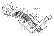
- the loading device of the here proposed type contains, as can be seen from Fig. 1 is an inclined downward Feed conveyor channel 1 for receiving stacks 2 of Conveyed goods 3, which in the from FIG. 2nd evident way placed in the feed channel 1 become.
- a discharge channel 4 leads from the lower end of the Feed channel 1 obliquely upwards.
- the slope of the Feed channel 1 is chosen to be large enough to be inside large stacks of items to be conveyed down into To let slip towards the discharge channel 4, but at the same time sufficiently low to the pressure of the Limit the stack to the lowest conveyed item.
- the feed channel 1 and the discharge channel 4 have a common right, seen in the direction of conveyance, angular side wall 5, a common, angular bottom 6 and a common one, in Direction of delivery seen left, angular side wall 7.
- the side wall 7 is attached to it on free leg with oblong holes in the angle 1 apparent in certain formats of the conveyed items in the direction transverse to the conveying direction adjustable.
- the bottom 6 of the feed channel 1 and Abinnekanals 4 is at the transition between the two Channels in the manner shown in FIG. 1 cut out such that the upper debris 8 out of three Conveyor belts 9 of a first conveyor belt unit 10 the bottom of the discharge channel 4 can be guided.
- the upper debris of the conveyor belts 9 thus follow that Course of the discharge channel 4 obliquely upwards and then go to the upper end of pulleys 11 supported in a horizontal course parallel to Level of a transfer table 12 above.
- the transfer table 12 is provided with longitudinal slots from which the Upper debris of the conveyor belts 9 in her horizontal section something about that Protrude table level.
- the lower debris of the conveyor belts 9 are over suitably positioned roles below the Transfer table 12 and below the floor of the Abddykanals 4 at the beginning of the conveyor near the transition between the feed channel and the discharge channel recycled.
- the first conveyor belt unit 10 Above the rubble 8 of the conveyor belts 9 the first conveyor belt unit 10 is a second Conveyor belt unit 13, the lower rubble of one Area before the change of direction of the upper rubble 8 to Horizontal run up to an area above the first Conveyor belt unit 10 in the horizontal section Opposite the first conveyor belt unit stand.
- This course of the conveyor belts 14 of the second Conveyor belt unit 13 is from FIGS. 1 and 2 without to recognize more. How symbolic by that Dashed line 15 indicated in Fig. 2, run the conveyor belts 9 of the first conveyor belt unit 10 and the conveyor belts 14 of the second conveyor belt unit 13 in sync. They are indicated by 16 in FIG indicated drive device put into circulation.
- the bottom of the discharge channel 4 is in one area between two conveyor belts 9 of the first Conveyor belt unit 10 with one in the conveying direction oriented cutout 17, from which something beyond the level of the bottom of the discharge channel 4 the upper run 18 of a circulating belt 19 (see Fig. 2) protrudes, the surface of which is low-friction.
- the circulating belt 19 is, as in Fig. 2 by the dash-dotted line 20 is indicated symbolically, synchronous and rectified to the conveyor belts 9 of the driven first conveyor belt unit 10.
- a stripper 21 acts as a counter surface, the training of which can be seen in detail from FIG. 3 is.
- a guide rail 22 is arranged, in which a Carriage 23 in a direction parallel to Delivery direction of the discharge channel 4 adjustable is held.
- the carriage 23 carries an arm 24 a wiper block 25, which in its lower part an approximately wedge-shaped wiper strip 26 made of rubber or plastic holds.
- the wiper strip 26 is a Pre-scraper 27 upstream.
- the distance of the bottom Edge of the wiper strip 26 from the surface of the Upper run 18 of the circulating belt 19 is by means of a setting knob 28 adjustable. Adjust by of the carriage 23 in the direction of the guide rail 22 can the position of the adjustment block 25 of the Scraper 21 to take into account the dimension of the Conveyed goods in the conveying direction along the upper run 18 of the circulating belt 19 can be set.
- the one with the upper run 18 of the circulating belt 19th as a counter surface interacting wipers 21 and Upper debris 8 of the conveyor belts 9 thus cause that between the conveyor belt units 10 and 13 scaled or staggered stream of Conveyed goods 3 arrives, the overlap distance or graduation distance on the stripper 21 is set.
- This scaled or staggered Stream of conveyed items 3 occurs on the output side between the conveyor belt units 10 and 13 on the Transfer table 12, which on a Tapping device 30 leads there in certain Distance from the output side of the first and second Conveyor belt unit is located and serves the front edge of the foremost conveyed item 3 to seize the scaled material flow and to subtract the piece of conveyed material in question in order to further handling or processing supply.
- the removal device 30 can in the Fig.
- FIG. 2 embodiment shown the shape of a Have conveyor chain 31, which from a drive 32nd is started cyclically as soon as one of the Conveyor chain 31 attached gripper 33 has captured the leading edge of a conveyed item 3.
- the upper claw of the gripper 33 is of spring means in the closed position against the lower gripper claw biased and will, as soon as the conveyor chain 31 Has gripper pliers 33 in the receiving position, by starting a cam of the upper gripper claw a cam 34 opened.
- Cam 34 can be closed by a drive 35 Gripper tongs are lowered.
- detectors for example Proximity detectors or light barriers report the respective operating position of the conveyor chain 31 and Gripper pliers 33.
- the conveyor chain 31 is located in that in FIG. 2 indicated operating position in which the gripper tongs 33 is receptive and open, one of them gives Drive or a resolver derived from the same Control signal from a control unit 36 a Request message via a control line 37 causes the drive 16 to the conveyor belt units 10th and 13 and the circulating belt 19 is put into operation and finally in the manner previously described the discharge side of the conveyor belt units 10 and 13 scaled flow of conveyed goods on the transfer table 12 exits.
- One following the detector 38 in the conveying direction second detector 39, which in turn from one in the Transfer table 12 mounted light barrier can be formed can then cause fine control of the drive 16 by the control unit 36 in such a way that the leading edge of the first conveyed item scaled material flow completely between the Gripper claws of the gripper tongs 33 is moved in and then through the upper gripper claw of the gripper tongs 33 Actuation of the cam plate 34 by means of the drive 35 is closed, after which the drive 32 is switched on is and the conveyor chain 31 to the first conveyed good its leading edge with reference to that in FIG. 2 shown position and position of the components subtracts to the left.
- the distance between that forming the detector 39 Light barrier and the bottom of the gripper 33 is so chosen that after the deduction of the first Piece of conveyed goods from the shingled flow of conveyed goods Light barrier or the detector 39 released again and for the fine positioning process of the then the first additional item to be conveyed is available. In any case, the distance mentioned is smaller than the minimum graduation distance or scaling distance of the conveyed items.
- the distance between the gripper 33 in the receiving position from the exit side of the gap between the Conveyor belt units 10 and 13 are selected so that a with its leading edge from the gripper 33 Conveyed piece of conveyed goods with its rear edge still held between the conveyor belt units 10 and 13 is.
- the removal device 30 and the transfer table 12 designed as a unit and on a trolley or carriage 40 movable in the conveying direction and adjustable so that the distance between the in Pickup position located gripper 33 and Output side of conveyor belt units 10 and 13 changed according to the format of the conveyed items can be.
- the roles to support the conveyor belts of the conveyor belt unit 13 are mounted on a common frame, the in turn around a horizontal one, to the bearing axes of the Rollers parallel axis can be pivoted such that the entire conveyor belt unit 13 for maintenance work or to eliminate interference from the Conveyor belt unit 10 is pivoted up.
- Relevant constructions familiar to the person skilled in the art as well as means for holding down the conveyed items in the area above the transfer table 12 are for Simplification of the representation in the drawing omitted.
- the removal device 30 can be operated according to the method shown in FIG. 4 shown modified embodiment also a Coupling pairs forming opposite one another Acceptance conveyor belts or rollers 41 and 42 contain the take-off conveyor rollers 42 by a drive 43 either lifted into a rest position or into one Conveying position against the acceptance conveyor belts 41 are lowerable. With this type of acceptance device 30, the conveyor belts 41 can run continuously.
- the upper run 18 of the revolving Volume 19 is a support and support surface for the Provide upper run 18, for example through part of the Soil 6 in that area of the upper run 18, about which way to set the format of the strippers 21 can be adjusted in the conveying direction of the belts 9.
- resolver output signals of the drive 32 for the conveyor chain 31 is determined when and via which Periods or drive section sections of the drive 16 for the conveyor belt units 10 and 13 in operation is set.
- Detectors 38 and 39 determine as Subordinate tax funds promoting the scaled material flow into the Gripper 33 or in the conveyor gap between the Conveyor belts 41 and the pressure rollers 42 (Fig. 4).
- Flaking or staggering is also a condition of To understand conveyed goods, in which these each other no longer overlap but already completely can be promoted individually to the transfer table 12.
Landscapes
- Engineering & Computer Science (AREA)
- Mechanical Engineering (AREA)
- Delivering By Means Of Belts And Rollers (AREA)
- Separation, Sorting, Adjustment, Or Bending Of Sheets To Be Conveyed (AREA)
- Branching, Merging, And Special Transfer Between Conveyors (AREA)
- De-Stacking Of Articles (AREA)
- Sheets, Magazines, And Separation Thereof (AREA)
Description
Die Erfindung betrifft eine Beschickungseinrichtung zur Aufgabe von flachem, flexiblem, in Stapel eingegebenem Fördergut, insbesondere von Kuverts, in eine Station zur weiteren einzelnen Handhabung.The invention relates to a loading device for loading flat, flexible, in stacks entered goods, especially envelopes, in a station for further individual handling.
Allgemein bekannt sind Beschickungseinrichtungen, bei denen das Fördergut als Stapel von Fördergutstücken in Magazine eingegeben wird, aus denen die Fördergutstücke einzeln, beispielsweise mittels Saugwalzen oder Greifern, abgezogen und in eine Station zur weiteren, einzelnen Handhabung übergeben werden.Feeding devices are generally known, where the material to be conveyed is a stack of items to be conveyed entered into magazines from which the Items conveyed individually, for example by means of Suction rolls or grippers, pulled off and into a station be handed over for further, individual handling.
Bei modernen Postbearbeitungsmaschinen, die mit sehr hohen Taktgeschwindigkeiten arbeiten, ist es notwendig, daß die Magazine der Beschickungseinrichtungen häufig von Hand mit Stapeln von Fördergutstücken gefüllt werden, da die Stapel in den Magazinen nicht eine bestimmte Höhe überschreiten sollen, um den Druck aufgrund des Gewichtes des Stapels an dessen unterem Ende in solchen Grenzen zu halten, daß die Einrichtungen zum Abzug der einzelnen Fördergutstücke dort zuverlässig arbeiten können.With modern mail processing machines that with work at very high clock speeds, it is necessary that the magazines of the Feeders often stacked by hand of goods to be conveyed as the stacks are filled in the magazines do not exceed a certain height are supposed to relieve the pressure due to the weight of the stack to keep at its lower end within such limits that the facilities for deducting the individual conveyed items can work reliably there.
Dem Problem einer häufigen Nachfüllung von Fördergutstapeln in Magazinen von bekannten Beschickungseinrichtungen begegnete man bereits durch Vorschaltung eines Beschickungsautomaten, der abhängig von einem ein Absinken des im Magazin befindlichen Stapels unter ein bestimmtes Niveau meldenden Signal aus einem langgestreckten, in einem Zuförderkanal etwa horizontal vorwärtsgeförderten Stapel hochkant stehender Fördergutstücke mittels schräg nach aufwärts fördernder, hohe Reibung zu den Fördergutstücken aufweisender Förderbänder Fördergutstücke zunächst nach aufwärts und dann, an einem Abstreifer vorbei etwa in horizontaler Richtung dem Magazin zuförderte, ohne hierbei allerdings eine Vereinzelung der Fördergutstücke vorzunehmen. Die Förderung des vorgeschalteten Beschickungsautomaten wurde so lange fortgesetzt, bis ein weiterer Detektor einen ausreichenden Füllungsgrad des Magazins meldete.The problem of frequent replenishment of Conveying goods in known magazines Feeding facilities have already been encountered through Upstream of an automatic loading device that depends one of which is a drop in that in the magazine Stack below signal signaling a certain level from an elongated, about in a feed channel horizontally fed stack upright upright conveyed items by sloping upwards promoting, high friction to the conveyed items Conveyor belts conveyed items first upwards and then, past a scraper about in horizontally fed to the magazine without here, however, a separation of the Make conveyed items. The promotion of upstream loading machine was so long continued until another detector detects one sufficient filling level of the magazine reported.
Aus der US-Patentschrift 5,088,718 ist eine Beschickungseinrichtung mit den Merkmalen des Oberbegriffes von Patentanspruch 1 bekannt. Bei dieser Beschickungseinrichtung wird ein Stapel blattartiger Fördergutstücke, welche auf der unteren Kante stehen, in einen Zuförderkanal gesetzt und gegen eine Förderrolle zur Einleitung einer Schuppung auf halber Höhe abgebogen, wobei die Förderrolle zusammen mit weiteren Förderrollen erste Fördermittel bilden, die einzelne blattartige Fördergutstücke von dem in einem horizontalen Mittenbereich abgebogenen Stapel abziehen, an einem von Rollen gebildeten Vereinzelungssystem vorbeifördern und dann wiederum Rollenpaaren zuleiten, die schließlich die Fördergutstücke in einen Horizontalabschnitt des Förderweges lenken und zweite Fördermittel darstellen.One is known from US Pat. No. 5,088,718 Feeding device with the characteristics of the The preamble of claim 1 is known. At this Feeder becomes a stack of sheets Conveyed goods that are on the lower edge placed in a feed channel and against one Conveyor role to initiate a shingling halfway Height bent, the conveyor roller together with form further funding roles first funding that individual sheet-like pieces of conveyed goods from the one in one Pull off the horizontal stack of the bent stack, on a separation system formed by rollers convey past and then in turn feed pairs of rollers, which finally converts the items to be conveyed into one Steer the horizontal section of the conveyor path and the second Represent subsidies.
Aus der US-Patentschrift 3,780,881 ist es ferner bekannt, von einem Stapel auf der Kante stehender Fördergutstücke mittels zweier einander gegenüberstehender Förderbandeinheiten einen geschuppten Strom von Fördergutstücken abzuziehen und wiederum als Stapel in ein Magazin einzulegen. Von diesem Magazin werden dann einzelne blattartige Fördergutstücke mittels einer Abfördereinrichtung abgezogen.It is also known from US Pat. No. 3,780,881 known to stand on a ledge from a pile Conveyed goods by means of two each other opposite conveyor belt units one subtract the shingled stream from conveyed goods and again in a stack in a magazine. Of this magazine then becomes individual sheet-like Conveyed goods by means of a removal device deducted.
Die US-Patentschrift 5,161,792 zeigt einen Zuförderkanal einer Beschickungseinrichtung mit in diesem Zuförderkanal angeordneten Förderbändern zur Bewegung von Stapeln aus auf der Kante stehenden Fördergutstücken in Richtung auf einen Abförderkanal, in welchem einander gegenüberstehende Förderbandeinheiten die einzelnen Fördergutstücke geschuppt nach aufwärts fördern.U.S. Patent 5,161,792 shows one Feed channel of a feeder with in this conveyor channel arranged conveyor belts Movement of stacks from the edge Conveyed items in the direction of a discharge channel, in which opposing Conveyor belt units the individual pieces of conveyed goods convey scaled upwards.
Aufgabe der vorliegenden Erfindung ist es, eine Beschickungseinrichtung zur Aufgabe von flachem, flexiblem, in Stapeln eingegebenem Fördergut, insbesondere von Kuverts, in eine Station zur weiteren einzelnen Handhabung so auszugestalten, daß keine starke Begrenzung der Zahl der stapelweise eingegebenen Fördergutstücke vorgenommen werden muß und eine Zwischenspeicherung der Fördergutstücke in einem Magazin vermieden wird.The object of the present invention is a loading device to give up flat, flexible material conveyed in stacks, especially from envelopes, in one station to another individual handling so that none strong limitation of the number of stacks entered Conveyed goods must be made and a Temporary storage of the conveyed items in one Magazine is avoided.
Diese Aufgabe wird erfindungsgemäß durch die Merkmale des anliegenden Patentanspruchs 1 gelöst. Vorteilhafte Ausgestaltungen und Weiterbildungen sind Gegenstand der dem Anspruch 1 nachgeordneten Patentansprüche, auf deren Inhalt hier ausdrücklich hingewiesen wird, ohne an dieser Stelle den Wortlaut zu wiederholen.This object is achieved by the Features of the attached claim 1 solved. Advantageous refinements and developments are Subject of the subordinate to claim 1 Claims, the content of which is expressly stated here is pointed out without the wording at this point to repeat.
Nachfolgend werden Ausführungsbeispiele anhand der
Zeichnung beschrieben. Es stellen dar:
Die Beschickungseinrichtung der hier
vorgeschlagenen Art enthält, wie aus Fig. 1 zu ersehen
ist, einen schräg nach abwärts verlaufenden
Zuförderkanal 1 zur Aufnahme von Stapeln 2 von
Fördergutstücken 3, welche in der aus Fig. 2
ersichtlichen Weise in den Zuförderkanal 1 gestellt
werden.The loading device of the here
proposed type contains, as can be seen from Fig. 1
is an inclined downward
Feed conveyor channel 1 for receiving stacks 2 of
Conveyed
Ein Abförderkanal 4 führt vom unteren Ende des Zuförderkanals 1 schräg nach aufwärts. Das Gefälle des Zuförderkanals 1 ist ausreichend groß gewählt, um darin große Stapel von Fördergutstücken nach abwärts in Richtung auf den Abförderkanal 4 rutschen zu lassen, gleichzeitig aber ausreichend gering, um den Druck des Stapels auf das unterste Fördergutstück zu begrenzen.A discharge channel 4 leads from the lower end of the Feed channel 1 obliquely upwards. The slope of the Feed channel 1 is chosen to be large enough to be inside large stacks of items to be conveyed down into To let slip towards the discharge channel 4, but at the same time sufficiently low to the pressure of the Limit the stack to the lowest conveyed item.
Der Zuförderkanal 1 und der Abförderkanal 4 haben
eine gemeinsame, in Förderrichtung gesehen rechte,
winkelförmige Seitenwand 5, einen gemeinsamen,
winkelförmigen Boden 6 und eine gemeinsame, in
Förderrichtung gesehen linke, winkelförmige Seitenwand
7. Die Seitenwand 7 ist durch daran befestigte, am
freien Schenkel mit Langlöchern versehene Winkel in der
aus Fig. 1 ersichtlichen Weise auf bestimmte Formate
der Fördergutstücke in Richtung quer zur Förderrichtung
einstellbar.The feed channel 1 and the discharge channel 4 have
a common right, seen in the direction of conveyance,
angular side wall 5, a common,
Der Boden 6 des Zuförderkanals 1 und des
Abförderkanals 4 ist am Übergang zwischen den beiden
Kanälen in der aus Fig. 1 erkennbaren Weise
ausgeschnitten, derart, daß die Obertrümmer 8 von drei
Förderbändern 9 einer ersten Förderbandeinheit 10 über
den Boden des Abförderkanals 4 geführt werden können.
Die Obertrümmer der Förderbänder 9 folgen also dem
Verlauf des Abförderkanals 4 schräg nach aufwärts und
gehen dann an dessen oberem Ende von Umlenkrollen 11
abgestützt in einen horizontalen Verlauf parallel zur
Ebene eines Übergabetisches 12 über. Der Übergabetisch
12 ist mit Längsschlitzen versehen, aus denen die
Obertrümmer der Förderbänder 9 in ihrem
horizontalverlaufenden Abschnitt etwas über das
Tischniveau vorstehen.The
Die Untertrümmer der Förderbänder 9 sind über geeignet positionierte Rollen unterhalb des Übergabetisches 12 und unterhalb des Bodens des Abförderkanals 4 zum Förderbandbeginn nahe dem Übergang zwischen dem Zuförderkanal und dem Abförderkanal zurückgeführt.The lower debris of the conveyor belts 9 are over suitably positioned roles below the Transfer table 12 and below the floor of the Abförderkanals 4 at the beginning of the conveyor near the transition between the feed channel and the discharge channel recycled.
Über den Obertrümmern 8 der Förderbänder 9 der
ersten Förderbandeinheit 10 befindet sich eine zweite
Förderbandeinheit 13, deren Untertrümmer von einem
Bereich vor dem Richtungswechsel der Obertrümmer 8 zum
Horizontalverlauf bis zu einem Bereich über der ersten
Förderbandeinheit 10 im horizontalen Abschnitt den
Obertrümmern der ersten Förderbandeinheit gegenüber
stehen. Dieser Verlauf der Förderbänder 14 der zweiten
Förderbandeinheit 13 ist aus den Fig. 1 und 2 ohne
weiteres zu erkennen. Wie symbolisch durch die
strichpunktierte Linie 15 in Fig. 2 angedeutet, laufen
die Förderbänder 9 der ersten Förderbandeinheit 10 und
die Förderbänder 14 der zweiten Förderbandeinheit 13
synchron um. Sie werden durch eine in Fig. 2 bei 16
angedeutete Antriebseinrichtung in Umlauf versetzt.Above the rubble 8 of the conveyor belts 9 the
first
Der Boden des Abförderkanals 4 ist in einem Bereich
zwischen zwei Förderbändern 9 der ersten
Förderbandeinheit 10 mit einem in Förderrichtung
orientierten Ausschnitt 17 versehen, aus welchem etwas
über das Niveau des Bodens des Abförderkanals 4 hinaus
das Obertrumm 18 eines umlaufenden Bandes 19 (siehe
Fig. 2) hervorsteht, dessen Oberfläche reibungsarm ist.
Das umlaufende Band 19 wird, wie in Fig. 2 durch die
strichpunktierte Linie 20 symbolisch angedeutet ist,
synchron und gleichgerichtet zu den Förderbändern 9 der
ersten Förderbandeinheit 10 angetrieben.The bottom of the discharge channel 4 is in one area
between two conveyor belts 9 of the first
Mit der glatten Oberfläche des umlaufenden Bandes
19 als Gegenfläche wirkt ein Abstreifer 21 zusammen,
dessen Ausbildung im einzelnen aus Fig. 3 ersichtlich
ist. Seitlich neben dem Abförderkanal 4 ist gestellfest
eine Führungsschiene 22 angeordnet, in welcher ein
Schlitten 23 in einer Richtung parallel zur
Förderrichtung des Abförderkanals 4 einstellbar
gehalten ist. Der Schlitten 23 trägt über einen Arm 24
einen Abstreiferblock 25, der in seinem unteren Teil
eine etwa keilförmige Abstreiferleiste 26 aus Kautschuk
oder Kunststoff hält. Der Abstreiferleiste 26 ist ein
Vorabstreifer 27 vorgelagert. Der Abstand der unteren
Kante der Abstreiferleiste 26 von der Oberfläche des
Obertrumms 18 des umlaufenden Bandes 19 ist mittels
eines Einstellknopfs 28 einstellbar. Durch verstellen
des Schlittens 23 in Richtung der Führungsschiene 22
kann die Stellung des Einstellblockes 25 des
Abstreifers 21 zur Berücksichtigung der Abmessung der
Fördergutstücke in Förderrichtung längs des Obertrumms
18 des umlaufenden Bandes 19 eingestellt werden.With the smooth surface of the circulating belt
19 a
Ist ein Stapel 2 von Fördergutstücken 3 in der aus
Fig. 2 ersichtlichen Weise in den zuförderkanal 1
eingesetzt, so werden die zuunterst liegenden
Fördergutstücke von den Obertrümmern 8 der Förderbänder
9 der Förderbandeinheit 10 längs des Abförderkanals 4
aufwärts gefördert, wobei weiter oben liegende
Fördergutstücke 3 von dem Vorabstreifer 7 zurückgehalten
werden und schließlich die
Abstreiferleiste 26 aufgrund des eingestellten Abstandes
zur Oberfläche des Obertrumms 18 des umlaufenden Bandes
19 zunächst jeweils nur den vorderen Teil eines
einzelnen Fördergutstückes dem Lauf der Förderbänder 9
folgen läßt, so daß dieser Teil des weiter geförderten
Fördergutstückes zwischen die Untertrümmer der
Förderbänder 14 der Förderbandeinheit 13 und die
Obertrümmer der Förderbänder 9 der Förderbandeinheit 10
gerät und zuverlässig weitergefördert wird. Ein sich
über die gesamte Breite der Förderbandeinheiten
erstreckender Umlenkschild 29, der in Fig. 2 angedeutet
ist, verhindert, daß seitlich von den Fördergutstücken
hochstehende Ecken oder Laschen ober dergleichen an
Anlageteilen anlaufen und zu Fehlförderungen führen
könnten. Is a stack 2 of conveyed
Der mit dem Obertrumm 18 des umlaufenden Bandes 19
als Gegenfläche zusammenwirkende Abstreifer 21 und die
Obertrümmer 8 der Förderbänder 9 bewirken somit, daß
zwischen die Förderbandeinheiten 10 und 13 ein
geschuppter oder gestaffelter Strom von
Fördergutstücken 3 einläuft, dessen Schuppungsabstand
oder Staffelungsabstand an dem Abstreifer 21
eingestellt wird. Dieser geschuppte oder gestaffelte
Strom von Fördergutstücken 3 tritt auf der Ausgabeseite
zwischen den Förderbandeinheiten 10 und 13 auf den
Übergabetisch 12 aus, welcher auf eine
Abnahmeeinrichtung 30 hinführt, die in bestimmten
Abstand von der Ausgabeseite der ersten und zweiten
Förderbandeinheit gelegen ist und dazu dient, den
vorderen Rand des jeweils vordersten Fördergutstückes 3
des geschuppten Fördergutstromes zu ergreifen und
taktweise das betreffende Fördergutstück abzuziehen, um
es einer weiteren Handhabung oder Bearbeitung
zuzuführen. Die Abnahmeeinrichtung 30 kann bei der in
Fig. 2 gezeigten Ausführungsform die Gestalt einer
Förderkette 31 haben, welche von einem Antrieb 32
taktweise in Tätigkeit gesetzt wird, sobald eine an der
Förderkette 31 befestigte Greiferzange 33 den
vorlaufenden Rand eines Fördergutstückes 3 erfaßt hat.
Die obere Klaue der Greiferzange 33 ist von Federmitteln
in Schließstellung gegen die untere Greiferklaue
vorgespannt und wird, sobald die Förderkette 31 die
Greiferzange 33 in die Aufnahmestellung geführt hat,
durch Anlaufen eines Nockens der oberen Greiferklaue an
eine Kurvenscheibe 34 geöffnet. Die Kurvenscheibe 34
kann mittels eines Antriebs 35 zum Schließen der
Greiferzange abgesenkt werden. In der Zeichnung nicht
eingezeichnete Detektoren, beispielsweise
Näherungsdetektoren oder Lichtschranken, melden die
jeweilige Betriebsstellung der Förderkette 31 und der
Greiferzange 33.The one with the
Befindet sich die Förderkette 31 in der in Fig. 2
angedeuteten Betriebsstellung, in der die Greiferzange
33 aufnahmebereit und geöffnet ist, so gibt ein von dem
Antrieb bzw. einem Drehmelder desselben abgeleitetes
Steuersignal einer Steuereinheit 36 eine
Anforderungsmeldung, die über eine Steuerleitung 37
bewirkt, daß der Antrieb 16 die Förderbandeinheiten 10
und 13 sowie das umlaufende Band 19 in Betrieb setzt
und schließlich in der zuvor beschriebenen Weise auf
der Abgabeseite der Förderbandeinheiten 10 und 13 ein
geschuppter Strom von Fördergutstücken auf den Übergabetisch
12 austritt.The
Sobald das erste Fördergutstück dieses geschuppten
Stromes von Fördergutstücken die einen ersten Detektor
38 bildende Lichtschranke abdeckt, bewirkt das
Ausgangssignal des Detektors 38, daß die Steuereinheit
36 den Antrieb 16 in einem Vorpositionierungsbetrieb
steuert, wozu bei vorausgesetzter konstanter
Antriebsgeschwindigkeit des Antriebs 16
Zeitsteuermittel der Steuereinheit 36 den Antrieb 16
für eine Dauer in Betrieb setzen, welche dazu
ausreicht, den vorlaufenden Rand des ersten
Fördergutstückes von dem Detektor 38 bis zu der
Greiferzange 33 zu bewegen.As soon as the first piece of conveyed material is shingled
Flow of conveyed items a first detector
That covers 38 forming light barriers
Output signal of the
Ein in Förderrichtung auf den Detektor 38 folgender
zweiter Detektor 39, der wiederum von einer in dem
Übergabetisch 12 montierten Lichtschranke gebildet sein
kann, bewirkt dann eine Feinsteuerung des Antriebs 16
durch die Steuereinheit 36 in der Weise, daß der
vorlaufende Rand des ersten Fördergutstückes des
geschuppten Fördergutstromes vollständig zwischen die
Greiferklauen der Greiferzange 33 hineinbewegt wird und
dann die obere Greiferklaue der Greiferzange 33 durch
Betätigung der Kurvenscheibe 34 mittels des Antriebs 35
geschlossen wird, wonach der Antrieb 32 angeschaltet
wird und die Förderkette 31 das erste Fördergutstück an
seinem vorlaufenden Rand mit Bezug auf die in Fig. 2
gezeigte Lage und Stellung der Bauteile nach links abzieht.One following the
Der Abstand zwischen der den Detektor 39 bildenden
Lichtschranke und dem Grund der Greiferzange 33 ist so
gewählt, daß nach dem Abzug des jeweils ersten
Fördergutstückes aus dem geschuppten Fördergutstrom die
Lichtschranke bzw. der Detektor 39 wieder freigegeben
wird und für den Feinpositionierungsvorgang des dann
ersten weiteren Fördergutstückes zur Verfügung steht.
Der genannte Abstand ist also jedenfalls kleiner als
der minimale Staffelungsabstand oder Schuppungsabstand
der Fördergutstücke.The distance between that forming the
Ferner ist zu bemerken, daß der Abstand zwischen
der in Aufnahmestellung befindlichen Greiferzange 33
von der Ausgangsseite des Spaltes zwischen den
Förderbandeinheiten 10 und 13 so gewählt ist, daß ein
mit seinem vorlaufenden Rand von der Greiferzange 33
gefaßtes Fördergutstück mit seinem hinteren Rand noch
zwischen den Förderbandeinheiten 10 und 13 gehalten
ist. Bei Betätigung der Förderkette 31 wird dann dieses
von der Zange 33 gefaßte Fördergutstück zwischen den
Förderbandeinheiten 10 und 13 gezogen. Zur Einstellung
auf unterschiedliche Formate der Fördergutstücke mit
Bezug auf die Förderrichtung sind, wie in Fig. 1 angedeutet,
die Abnahmeeinrichtung 30 und der Übergabetisch
12 als Geräteeinheit ausgebildet und auf einem Wagen
oder Schlitten 40 in Förderrichtung verfahrbar und
einstellbar, damit der Abstand zwischen der in
Aufnahmestellung befindlichen Greiferzange 33 und der
Ausgangsseite der Förderbandeinheiten 10 und 13
entsprechend dem Format der Fördergutstücke verändert
werden kann. Weiterhin sei angemerkt, daß die Rollen
zur Abstützung der Förderbänder der Förderbandeinheit
13 an einem gemeinsamen Rahmen gelagert sind, der
seinerseits um eine horizontale, zu den Lagerachsen der
Rollen parallele Achse derart verschwenkt werden kann,
daß die gesamte Förderbandeinheit 13 zu Wartungsarbeiten
oder zur Beseitigung von Störungen von der
Förderbandeinheit 10 hochschwenkbar ist.
Diesbezügliche, dem Fachmann geläufige Konstruktionen
sowie auch Mittel zur Niederhaltung der Fördergutstücke
im Bereich oberhalb des Übergabetisches 12 sind zur
Vereinfachung der Darstellung in der Zeichnung
weggelassen.It should also be noted that the distance between
the gripper 33 in the receiving position
from the exit side of the gap between the
Conveyor
Die Abnahmeeinrichtung 30 kann gemäß der in Fig. 4
gezeigten abgewandelten Ausführungsform auch einen
Förderspalt bildende Paare einander gegenüberstehender
Abnahmeförderbänder bzw. Rollen 41 und 42 enthalten,
wobei die Abnahmeförderrollen 42 durch einen Antrieb 43
entweder in eine Ruhestellung anhebbar oder in eine
Förderstellung gegen die Abnahmeförderbänder 41
absenkbar sind. Bei dieser Form der Abnahmeeinrichtung
30 können die Förderbänder 41 kontinuierlich umlaufen.
Sobald nach Ansprechen des Detektors 39 der vorlaufende
Rand eines Fördergutstückes 3 zwischen die
Abnahmeförderbänder 41 und die Abnahmeförderrollen 42
bewegt worden ist, drückt der Antrieb 43 die
Abnahmeförderrollen nach abwärts, wodurch das vorderste
Fördergutstück 3 aus dem geschuppten Strom der
Fördergutstücke und mit seinem nachlaufenden Rand
zwischen den Förderbandeinheiten 10 und 13
herausgezogen wird und sich die im Zusammenhang mit den
Fig. 1 und 2 erläuterten Vorgänge wiederholen.The removal device 30 can be operated according to the method shown in FIG. 4
shown modified embodiment also a
Coupling pairs forming opposite one another
Acceptance conveyor belts or
Die Konstruktion des vornehmlich in Fig. 3
gezeigten Abstreifers 21 ist insofern von selbständiger
Bedeutung, als aufgrund der harten, glatten Oberfläche
des umlaufenden Bandes 19 in Zusammenwirkung mit dem
Vorabstreifer 27 und der Kante der Abstreiferleiste 26
eine sehr präzise Einstellung des Schuppungsergebnisses
und insoweit der Vereinzelung bei Förderung durch die
Förderbänder 9 gegeben ist, und auch durch Vorsehen des
umlaufenden Bandes 19 eine Formateinstellung durch
Verfahren des Schlittens 23 in der Führungsschiene 22
vorgenommen werden kann. Es kann hierbei zweckmäßig
sein, unterhalb des Obertrumms 18 des umlaufenden
Bandes 19 eine Gegenhaltungs- und Stützfläche für das
Obertrumm 18 vorzusehen, etwa durch einen Teil des
Bodens 6 in demjenigen Bereich des Obertrumms 18, über
welchen hinweg zur Formateinstellung der Abstreifer 21
in Förderrichtung der Bänder 9 verstellt werden kann.The construction of the primarily in Fig. 3rd
shown
Bezüglich der Steuereinrichtung 36 ist zu sagen,
daß durch Drehmelderausgangssignale des Antriebs 32 für
die Förderkette 31 bestimmt wird, wann und über welche
Zeiträume bzw. Antriebsstreckenabschnitte der Antrieb
16 für die Förderbandeinheiten 10 und 13 in Betrieb
gesetzt wird. Die Detektoren 38 und 39 bestimmen als
nachgeordnete Steuermittel die Förderung des
geschuppten Fördergutstromes bis hinein in die
Greiferzange 33 bzw. in den Förderspalt zwischen die
Förderbänder 41 und die Andruckrollen 42 (Fig. 4).Regarding the
In der obigen Beschreibung ist allerdings unter Schuppung oder Staffelung auch ein Zustand der Fördergutstücke zu verstehen, in welchem diese einander nicht mehr überlappen sondern bereits vollständig vereinzelt auf den Übergabetisch 12 gefördert werden.In the above description, however, is below Flaking or staggering is also a condition of To understand conveyed goods, in which these each other no longer overlap but already completely can be promoted individually to the transfer table 12.
Claims (11)
- Feeding machine for feeding flat, flexible items which are input in stacks and standing upright into a station for further individual handling, havingcharacterized in thata) a downwardly inclined feed channel (1) for receiving the stack (2) of conveyed items;b) a discharge channel (4) which leads obliquely upwards from the lower end of the feed channel and on whose base side first conveying means (10), which have increased friction with respect to the lowermost conveyed item and have an obliquely upwardly directed conveying direction and, after a change of direction, with a conveying direction corresponding to the discharge direction with a less positive gradient, in particular with a horizontal conveying direction, are arranged;c) second conveying means (13) which are located directly opposite the first conveying means (10) in a region before the change of direction and a region of less positive gradient of the conveying direction, in particular a horizontal section; andd) a separation device (21) which is active in the discharge channel (4), underneath the region of the change of direction and serves to imbricate the stream of conveyed items which are conveyed upwards from the stack (2);the first conveying means are formed by first conveyor belts (9) whose upper strands (8) extend obliquely upwards and, with the aforesaid change in direction, extend in the discharge direction with a less positive gradient, in particular horizontally;the second conveying means are formed by a second conveyor belt unit (13), whose lower strands are located directly opposite the upper strands (8) of the aforementioned conveyor belts (9) from a region before the change of direction as far as to a region above the first conveying means (10) in the section with a less positive gradient, in particular the horizontal section;the separating device is formed by an imbricator strip (21) which extends in the discharge channel (4) between the two first-mentioned conveyor belts (9) underneath the region of the change of direction, towards an opposite face (18);a removal device (30) is provided which, on the outward side of the aforementioned conveyor belts and of the second conveyor belt unit (10, 13), picks up, at a specific distance from said units (10, 13) the leading edge of individual conveyed items and pulls them off in a clocked fashion, anda detector arrangement (38, 39) is provided which contains at least one detector which responds to the arrival of the leading edge of a conveyed item (3) and, in response thereto , controls the activation of the removal device (30) and/or of the first-mentioned conveyor belts and of the second conveyor belt unit (10, 13).
- Feeding machine according to Claim 1, characterized in that the feed channel (1) and the discharge channel (4) have a side wall (7) for oblong format setting, said side wall (7) being adjustable with respect to a respective base part (6).
- Feeding machine according to Claim 1 or 2, characterized in that the imbricator strip (21) is adjustable (22, 23, 24) parallel to the conveying direction of the conveyor belt units (10, 13) for longitudinal format setting.
- Feeding machine according to one of Claims 1 to 3, characterized in that the imbricator strip can be set (26, 28) perpendicularly to the opposite face (18) in order to set the shingling result.
- Feeding machine according to one of Claims 1 to 4, characterized in that the imbricator strip interacts with a belt (19), which has a low-friction surface, forms the opposite face, is driven in the same direction as the conveyor belts of the conveyor belt units (10,13) and is positioned between two conveyor belts (19) of the first conveyor belt unit (10).
- Feeding machine according one of the Claims 1 to 5, characterized in that the removal device (30) has pairs of removal conveyor belts (41) or contacting rollers (42) which form a conveyor gap and whose drive or conveying function is controlled in operating cycles, in particular by the detector arrangement (38, 39).
- Feeding machine according to one of the Claims 1 to 5, characterized in that the removal device (30) contains a conveying chain (31) which is equipped with gripper tongs (33) whose opening and closing is controlled in operating cycles.
- Feeding machine according to one of the Claims 1 to 7, characterized in that the detector arrangement contains two detectors (38, 39), the first of which is arranged just behind the delivery side of the first and second conveyor belt units (10, 13) in the conveying direction and serves to generate a detector signal which is used to preposition the stream of imbricated conveyed items, and the second (39) of which is positioned just in front of the removal device (30) at a distance which is shorter than the minimum separation distance or imbrication distance of the stream of conveyed items.
- Feeding machine according to one of the Claims 1 to 8, characterized in that the removal device (30) pulls out, in operating cycles, individual conveyed items from the imbricated stream of conveyed items, the trailing edge of the extracted conveyed item at that time still being located between the conveyor belts of the first and second conveyor belt units (10, 13).
- Feeding machine according to Claim 8 or 9, characterized in that the detector output signal of the second detector (39) causes the drive of the first and second conveyor belt units (10, 13) to carry out a measured conveying displacement of the leading edge of a conveyed item from the second detector to the removal position of the removing device (30).
- Feeding machine according to one of the Claims 1 to 10, characterized in that the distance between the removal device (30) and the delivery side of the first and second conveyor belt units (10, 13) is adjustable.
Applications Claiming Priority (3)
| Application Number | Priority Date | Filing Date | Title |
|---|---|---|---|
| DE19735382A DE19735382A1 (en) | 1997-08-14 | 1997-08-14 | Feed device for output of envelopes from stack |
| DE19735382 | 1997-08-14 | ||
| PCT/EP1998/005131 WO1999008951A1 (en) | 1997-08-14 | 1998-08-12 | Feeding machine |
Publications (2)
| Publication Number | Publication Date |
|---|---|
| EP1003684A1 EP1003684A1 (en) | 2000-05-31 |
| EP1003684B1 true EP1003684B1 (en) | 2002-03-20 |
Family
ID=7839051
Family Applications (1)
| Application Number | Title | Priority Date | Filing Date |
|---|---|---|---|
| EP98948830A Expired - Lifetime EP1003684B1 (en) | 1997-08-14 | 1998-08-12 | Feeding machine |
Country Status (6)
| Country | Link |
|---|---|
| US (1) | US6375182B1 (en) |
| EP (1) | EP1003684B1 (en) |
| JP (1) | JP2001515002A (en) |
| CA (1) | CA2300183C (en) |
| DE (2) | DE19735382A1 (en) |
| WO (1) | WO1999008951A1 (en) |
Cited By (1)
| Publication number | Priority date | Publication date | Assignee | Title |
|---|---|---|---|---|
| US7900915B2 (en) | 2007-11-28 | 2011-03-08 | Wipotec Wiege-Und Positioniersysteme Gmbh | Device for transporting and weighing letters |
Families Citing this family (16)
| Publication number | Priority date | Publication date | Assignee | Title |
|---|---|---|---|---|
| DE10027874C1 (en) * | 2000-06-06 | 2001-11-22 | Siemens Ag | Overlapping letters detection device for automatic letter handling detects interruption of light barrier by overlapping letter upon deflection of leading letter |
| DE10126114A1 (en) * | 2001-05-30 | 2002-12-05 | Kolbus Gmbh & Co Kg | Feeder for feeding covers to binder has feed rollers with controlled drive which is adjusted according to height of covers so that they are fed with their rear edges against holders on chain conveyor |
| FR2830242B1 (en) * | 2001-10-01 | 2004-06-11 | Plus Dev B | METHOD AND INSTALLATION FOR SUPPLYING HIGH-THROUGHPUT MACHINES OR LINES OPERATING ON FLAT OBJECTS |
| JP2005225617A (en) * | 2004-02-13 | 2005-08-25 | Hebaroido Kk | Sharp inclination belt conveyor using thermosensitive adhesive tape |
| DE102004030254B3 (en) * | 2004-06-23 | 2005-09-22 | Pitney Bowes Deutschland Gmbh | Rotary feeder for conveying side dishes |
| EP1888438A4 (en) * | 2005-03-16 | 2011-03-16 | James C Kaiping | Sheet feeder |
| US20100264575A1 (en) * | 2009-04-20 | 2010-10-21 | Bowe Bell + Howell Company | Booklet feeder systems and methods |
| US20160159140A1 (en) * | 2013-11-13 | 2016-06-09 | T.S.D. Llc | Apparatus for inserting documents into envelopes and associated method |
| DE102014006253A1 (en) * | 2014-04-28 | 2015-10-29 | Giesecke & Devrient Gmbh | stripping |
| CN105502048B (en) * | 2016-01-18 | 2017-11-14 | 浙江中轴物流设备有限公司 | A kind of belt feeder for conveying paper |
| CN107261333B (en) * | 2017-04-17 | 2019-06-07 | 宁波中哲医疗科技有限公司 | Storing, the discharging mechanism of carbon-point apparatus for automatic change |
| CN109178995B (en) * | 2018-09-29 | 2023-11-03 | 湖南中天云科电子有限公司 | Conveying mechanism of electronic letter issuing machine |
| CN108946116B (en) * | 2018-09-29 | 2024-02-09 | 湖南中天云科电子有限公司 | Electronic letter issuing machine |
| KR101988864B1 (en) * | 2019-01-04 | 2019-06-13 | 조성국 | Pre Feeder For Paper For Box |
| CN111942922B (en) * | 2020-09-18 | 2023-08-08 | 玉田县团结包装机械有限公司 | Automatic feeding and conveying device for printing and packaging |
| CN118205774B (en) * | 2024-05-21 | 2024-07-19 | 成都徕伯益科技有限公司 | Continuous high-speed film sealing mechanism and film sealing machine |
Family Cites Families (23)
| Publication number | Priority date | Publication date | Assignee | Title |
|---|---|---|---|---|
| US3664660A (en) * | 1967-12-20 | 1972-05-23 | Ruenzi Kurt | Device for feeding flat objects to a processing machine |
| US3780881A (en) * | 1973-02-14 | 1973-12-25 | Container Corp | Mobile structure for handling flat articles |
| DE2825420A1 (en) | 1978-06-09 | 1979-12-13 | Jagenberg Werke Ag | STORAGE IN A FOLDING BOX PACKAGING MACHINE |
| IT1166837B (en) | 1979-05-18 | 1987-05-06 | Omg Off Macch Grafic | LOADER OF SIGNATURES, SHEETS, FILES AND SIMILARS, IN PARTICULAR FOR COLLECTORS, CROSS-LINERS, STITCHERS AND SIMILAR BINDING MACHINES |
| JPS6178630A (en) * | 1984-09-27 | 1986-04-22 | サンエンヂニアリング株式会社 | Paper feeder for box making machine |
| US4832179A (en) | 1986-07-26 | 1989-05-23 | Burtons Gold Medal Biscuits Limited | Conveyor systems |
| US4809964A (en) * | 1987-04-17 | 1989-03-07 | St. Denis Manufacturing Co. | Apparatus and method for converting bundled signatures to a shingled stream |
| US5057066A (en) | 1988-04-28 | 1991-10-15 | Tokyo Automatic Machinery Works, Ltd. | Magazine and method of feeding articles |
| US4930764A (en) | 1988-12-28 | 1990-06-05 | Pitney Bowes Inc. | Front end feeder for mail handling machine |
| US4973037A (en) | 1988-12-28 | 1990-11-27 | Pitney Bowes Inc. | Front end feeder for mail handling machine |
| US4978114A (en) | 1989-11-14 | 1990-12-18 | Pitney Bowes Inc. | Reverse belt singulating apparatus |
| US5088718A (en) * | 1990-12-06 | 1992-02-18 | Pitney Bowes Inc. | High capacity sheet feeder |
| US5154408A (en) | 1990-12-28 | 1992-10-13 | Pitney Bowes Inc. | High capacity sheet feeder with adjustable deck |
| US5161792A (en) * | 1991-05-08 | 1992-11-10 | St. Denis Manufacturing Co. | Machine for transforming a stack of signatures into a shingled stream |
| DE9110473U1 (en) * | 1991-08-23 | 1991-12-05 | Mathias Bäuerle GmbH, 7742 St Georgen | Sheet stack pre-feeder |
| US5192069A (en) * | 1992-03-05 | 1993-03-09 | Ncr Corporation | Document feeder employing a belt |
| US5211529A (en) | 1992-03-27 | 1993-05-18 | R. A. Pearson Company | Horizontal staging hopper |
| FR2689038A1 (en) | 1992-03-27 | 1993-10-01 | Cga Hbs | Device for arranging a pile of flat objects on edge toward an unloading head of an automatic sorting system and method for implementing this device. |
| FR2700529B1 (en) | 1993-01-19 | 1995-02-24 | Cga Hbs | Mail processing machine having a mechanical roller jogger. |
| US5508818A (en) | 1994-09-23 | 1996-04-16 | Scan-Code, Inc. | Mixed mail transport |
| US5601282A (en) * | 1995-09-18 | 1997-02-11 | Milo; Alfred | Shingle feeder |
| DE19780381B4 (en) | 1996-04-01 | 2008-10-30 | Documotion Inc. | Sheet feeder for various thickness sheets etc. stacked to varying heights - includes prompter to move sheet comprising belt running round rollers linked by body and driven by rotating shaft attached to front roller |
| US5775871A (en) | 1996-09-18 | 1998-07-07 | Exide Corporation | Rollerless plate-feeding apparatus |
-
1997
- 1997-08-14 DE DE19735382A patent/DE19735382A1/en not_active Withdrawn
-
1998
- 1998-08-12 WO PCT/EP1998/005131 patent/WO1999008951A1/en active IP Right Grant
- 1998-08-12 JP JP2000509649A patent/JP2001515002A/en not_active Withdrawn
- 1998-08-12 EP EP98948830A patent/EP1003684B1/en not_active Expired - Lifetime
- 1998-08-12 US US09/485,429 patent/US6375182B1/en not_active Expired - Fee Related
- 1998-08-12 DE DE59803446T patent/DE59803446D1/en not_active Expired - Fee Related
- 1998-08-12 CA CA002300183A patent/CA2300183C/en not_active Expired - Fee Related
Cited By (1)
| Publication number | Priority date | Publication date | Assignee | Title |
|---|---|---|---|---|
| US7900915B2 (en) | 2007-11-28 | 2011-03-08 | Wipotec Wiege-Und Positioniersysteme Gmbh | Device for transporting and weighing letters |
Also Published As
| Publication number | Publication date |
|---|---|
| DE19735382A1 (en) | 1999-02-18 |
| CA2300183A1 (en) | 1999-02-25 |
| EP1003684A1 (en) | 2000-05-31 |
| US6375182B1 (en) | 2002-04-23 |
| WO1999008951A1 (en) | 1999-02-25 |
| CA2300183C (en) | 2007-10-30 |
| JP2001515002A (en) | 2001-09-18 |
| DE59803446D1 (en) | 2002-04-25 |
Similar Documents
| Publication | Publication Date | Title |
|---|---|---|
| EP1003684B1 (en) | Feeding machine | |
| EP1084072B1 (en) | Device and method for individually separating a pile of sheetlike data recording media | |
| DE2627335A1 (en) | SHEET PULLING AND CUTTING DEVICE WITH PILE LEVELING DEVICE | |
| EP0722415B1 (en) | Process and device for forming and moving stacks of printed sheets | |
| EP0368009A1 (en) | Method and device for advancing printed articles | |
| DE69301614T2 (en) | Device for storing and stacking sheets of sheet material | |
| EP1622778A1 (en) | Device for inserting sheets into an envelope | |
| WO1982000995A1 (en) | Device for stacking overlapping plane products,particularly printed products | |
| DE10219982C1 (en) | Method of continuously separating paper blanks has feed belt with roller to engage underside of lowest blank in stack positioned by guide tongue | |
| EP1332891B1 (en) | Mail handling system | |
| DE2024150C3 (en) | Method and device for the continuous formation of stacks from printing layers | |
| EP1748013A1 (en) | Apparatus for collating printed sheets | |
| EP0810966B1 (en) | Device for generating a flow of plies of adjustable thickness | |
| EP0806391B1 (en) | Device for feeding printed articles to a further work station | |
| EP0185395B1 (en) | Device for separating sheets | |
| DE102010043063B4 (en) | Apparatus and method for buffering a plurality of goods or crop groups and paper handling equipment therewith | |
| EP1748012B1 (en) | Method and device for collecting sheets | |
| DE3514487C2 (en) | ||
| EP0578614B1 (en) | Device for conveying printed products fed in a shingled stream | |
| EP0499691A1 (en) | Method for handling printed products fed in a continuous overlapping formation and device for carrying out said method | |
| DE3112418A1 (en) | Separating device for separating sheets of a sheet stack | |
| EP2815994A1 (en) | Insertion device for flat articles, in particular insertion device for inserts and method for withdrawing flat goods from a stack | |
| DE3531145C2 (en) | ||
| DE10157098A1 (en) | Device for transporting and stacking in particular tabular goods and corresponding method | |
| DE102007039259B3 (en) | Feeding device and method for feeding sheets from a stack |
Legal Events
| Date | Code | Title | Description |
|---|---|---|---|
| PUAI | Public reference made under article 153(3) epc to a published international application that has entered the european phase |
Free format text: ORIGINAL CODE: 0009012 |
|
| 17P | Request for examination filed |
Effective date: 20000215 |
|
| AK | Designated contracting states |
Kind code of ref document: A1 Designated state(s): CH DE FR GB LI |
|
| GRAG | Despatch of communication of intention to grant |
Free format text: ORIGINAL CODE: EPIDOS AGRA |
|
| 17Q | First examination report despatched |
Effective date: 20010601 |
|
| GRAG | Despatch of communication of intention to grant |
Free format text: ORIGINAL CODE: EPIDOS AGRA |
|
| GRAH | Despatch of communication of intention to grant a patent |
Free format text: ORIGINAL CODE: EPIDOS IGRA |
|
| GRAH | Despatch of communication of intention to grant a patent |
Free format text: ORIGINAL CODE: EPIDOS IGRA |
|
| RAP1 | Party data changed (applicant data changed or rights of an application transferred) |
Owner name: PITNEY BOWES TECHNOLOGIES GMBH |
|
| REG | Reference to a national code |
Ref country code: GB Ref legal event code: IF02 |
|
| GRAA | (expected) grant |
Free format text: ORIGINAL CODE: 0009210 |
|
| AK | Designated contracting states |
Kind code of ref document: B1 Designated state(s): CH DE FR GB LI |
|
| REG | Reference to a national code |
Ref country code: CH Ref legal event code: EP |
|
| REG | Reference to a national code |
Ref country code: CH Ref legal event code: NV Representative=s name: KELLER & PARTNER PATENTANWAELTE AG |
|
| REF | Corresponds to: |
Ref document number: 59803446 Country of ref document: DE Date of ref document: 20020425 |
|
| GBT | Gb: translation of ep patent filed (gb section 77(6)(a)/1977) |
Effective date: 20020620 |
|
| ET | Fr: translation filed | ||
| PGFP | Annual fee paid to national office [announced via postgrant information from national office to epo] |
Ref country code: DE Payment date: 20020827 Year of fee payment: 5 |
|
| PLBE | No opposition filed within time limit |
Free format text: ORIGINAL CODE: 0009261 |
|
| STAA | Information on the status of an ep patent application or granted ep patent |
Free format text: STATUS: NO OPPOSITION FILED WITHIN TIME LIMIT |
|
| 26N | No opposition filed |
Effective date: 20021223 |
|
| REG | Reference to a national code |
Ref country code: CH Ref legal event code: PFA Owner name: PITNEY BOWES DEUTSCHLAND GMBH Free format text: PITNEY BOWES TECHNOLOGIES GMBH#GRUENER WEG 8#61169 FRIEDBERG (DE) -TRANSFER TO- PITNEY BOWES DEUTSCHLAND GMBH#GRUENER WEG 8#61169 FRIEDBERG (DE) |
|
| REG | Reference to a national code |
Ref country code: CH Ref legal event code: PFA Owner name: PITNEY BOWES DEUTSCHLAND GESELLSCHAFT MIT BESCHRA Free format text: PITNEY BOWES DEUTSCHLAND GESELLSCHAFT MIT BESCHRAENKTER HAFTUNG#GRUENER WEG 8#61169 FRIEDBERG (DE) -TRANSFER TO- PITNEY BOWES DEUTSCHLAND GESELLSCHAFT MIT BESCHRAENKTER HAFTUNG#TIERGARTENSTRASSE 7#64646 HEPPENHEIM (DE) |
|
| PG25 | Lapsed in a contracting state [announced via postgrant information from national office to epo] |
Ref country code: DE Free format text: LAPSE BECAUSE OF NON-PAYMENT OF DUE FEES Effective date: 20040302 |
|
| REG | Reference to a national code |
Ref country code: GB Ref legal event code: 732E |
|
| REG | Reference to a national code |
Ref country code: FR Ref legal event code: CD |
|
| PGFP | Annual fee paid to national office [announced via postgrant information from national office to epo] |
Ref country code: CH Payment date: 20070827 Year of fee payment: 10 |
|
| PGFP | Annual fee paid to national office [announced via postgrant information from national office to epo] |
Ref country code: FR Payment date: 20070817 Year of fee payment: 10 |
|
| REG | Reference to a national code |
Ref country code: CH Ref legal event code: PL |
|
| REG | Reference to a national code |
Ref country code: FR Ref legal event code: ST Effective date: 20090430 |
|
| PG25 | Lapsed in a contracting state [announced via postgrant information from national office to epo] |
Ref country code: LI Free format text: LAPSE BECAUSE OF NON-PAYMENT OF DUE FEES Effective date: 20080831 Ref country code: CH Free format text: LAPSE BECAUSE OF NON-PAYMENT OF DUE FEES Effective date: 20080831 |
|
| PG25 | Lapsed in a contracting state [announced via postgrant information from national office to epo] |
Ref country code: FR Free format text: LAPSE BECAUSE OF NON-PAYMENT OF DUE FEES Effective date: 20080901 |
|
| PGFP | Annual fee paid to national office [announced via postgrant information from national office to epo] |
Ref country code: GB Payment date: 20100825 Year of fee payment: 13 |
|
| GBPC | Gb: european patent ceased through non-payment of renewal fee |
Effective date: 20110812 |
|
| PG25 | Lapsed in a contracting state [announced via postgrant information from national office to epo] |
Ref country code: GB Free format text: LAPSE BECAUSE OF NON-PAYMENT OF DUE FEES Effective date: 20110812 |