EP1003395B1 - Beutel mit komplementären profilverschlussstreifen mit schieber - Google Patents
Beutel mit komplementären profilverschlussstreifen mit schieber Download PDFInfo
- Publication number
- EP1003395B1 EP1003395B1 EP99925120A EP99925120A EP1003395B1 EP 1003395 B1 EP1003395 B1 EP 1003395B1 EP 99925120 A EP99925120 A EP 99925120A EP 99925120 A EP99925120 A EP 99925120A EP 1003395 B1 EP1003395 B1 EP 1003395B1
- Authority
- EP
- European Patent Office
- Prior art keywords
- bag
- bag according
- slider
- sheets
- sealing
- Prior art date
- Legal status (The legal status is an assumption and is not a legal conclusion. Google has not performed a legal analysis and makes no representation as to the accuracy of the status listed.)
- Expired - Lifetime
Links
Images


Classifications
-
- B—PERFORMING OPERATIONS; TRANSPORTING
- B65—CONVEYING; PACKING; STORING; HANDLING THIN OR FILAMENTARY MATERIAL
- B65D—CONTAINERS FOR STORAGE OR TRANSPORT OF ARTICLES OR MATERIALS, e.g. BAGS, BARRELS, BOTTLES, BOXES, CANS, CARTONS, CRATES, DRUMS, JARS, TANKS, HOPPERS, FORWARDING CONTAINERS; ACCESSORIES, CLOSURES, OR FITTINGS THEREFOR; PACKAGING ELEMENTS; PACKAGES
- B65D33/00—Details of, or accessories for, sacks or bags
- B65D33/02—Local reinforcements or stiffening inserts, e.g. wires, strings, strips or frames
-
- B—PERFORMING OPERATIONS; TRANSPORTING
- B65—CONVEYING; PACKING; STORING; HANDLING THIN OR FILAMENTARY MATERIAL
- B65D—CONTAINERS FOR STORAGE OR TRANSPORT OF ARTICLES OR MATERIALS, e.g. BAGS, BARRELS, BOTTLES, BOXES, CANS, CARTONS, CRATES, DRUMS, JARS, TANKS, HOPPERS, FORWARDING CONTAINERS; ACCESSORIES, CLOSURES, OR FITTINGS THEREFOR; PACKAGING ELEMENTS; PACKAGES
- B65D33/00—Details of, or accessories for, sacks or bags
- B65D33/16—End- or aperture-closing arrangements or devices
- B65D33/25—Riveting; Dovetailing; Screwing; using press buttons or slide fasteners
- B65D33/2508—Riveting; Dovetailing; Screwing; using press buttons or slide fasteners using slide fasteners with interlocking members having a substantially uniform section throughout the length of the fastener; Sliders therefor
- B65D33/2541—Riveting; Dovetailing; Screwing; using press buttons or slide fasteners using slide fasteners with interlocking members having a substantially uniform section throughout the length of the fastener; Sliders therefor characterised by the slide fastener, e.g. adapted to interlock with a sheet between the interlocking members having sections of particular shape
-
- A—HUMAN NECESSITIES
- A44—HABERDASHERY; JEWELLERY
- A44B—BUTTONS, PINS, BUCKLES, SLIDE FASTENERS, OR THE LIKE
- A44B19/00—Slide fasteners
- A44B19/10—Slide fasteners with a one-piece interlocking member on each stringer tape
- A44B19/16—Interlocking member having uniform section throughout the length of the stringer
-
- A—HUMAN NECESSITIES
- A44—HABERDASHERY; JEWELLERY
- A44B—BUTTONS, PINS, BUCKLES, SLIDE FASTENERS, OR THE LIKE
- A44B19/00—Slide fasteners
- A44B19/24—Details
- A44B19/26—Sliders
- A44B19/267—Sliders for slide fasteners with edges of stringers having uniform section throughout the length thereof
-
- Y—GENERAL TAGGING OF NEW TECHNOLOGICAL DEVELOPMENTS; GENERAL TAGGING OF CROSS-SECTIONAL TECHNOLOGIES SPANNING OVER SEVERAL SECTIONS OF THE IPC; TECHNICAL SUBJECTS COVERED BY FORMER USPC CROSS-REFERENCE ART COLLECTIONS [XRACs] AND DIGESTS
- Y10—TECHNICAL SUBJECTS COVERED BY FORMER USPC
- Y10T—TECHNICAL SUBJECTS COVERED BY FORMER US CLASSIFICATION
- Y10T24/00—Buckles, buttons, clasps, etc.
- Y10T24/25—Zipper or required component thereof
- Y10T24/2532—Zipper or required component thereof having interlocking surface with continuous cross section
- Y10T24/2534—Opposed interlocking surface having dissimilar cross section
-
- Y—GENERAL TAGGING OF NEW TECHNOLOGICAL DEVELOPMENTS; GENERAL TAGGING OF CROSS-SECTIONAL TECHNOLOGIES SPANNING OVER SEVERAL SECTIONS OF THE IPC; TECHNICAL SUBJECTS COVERED BY FORMER USPC CROSS-REFERENCE ART COLLECTIONS [XRACs] AND DIGESTS
- Y10—TECHNICAL SUBJECTS COVERED BY FORMER USPC
- Y10T—TECHNICAL SUBJECTS COVERED BY FORMER US CLASSIFICATION
- Y10T24/00—Buckles, buttons, clasps, etc.
- Y10T24/44—Clasp, clip, support-clamp, or required component thereof
- Y10T24/44291—Clasp, clip, support-clamp, or required component thereof including pivoted gripping member
Definitions
- the present invention relates to the field of sachets comprising complementary closure profiles actuated respectively at opening and closing with a cursor.
- the sliders make it easier to open and close the bags.
- the presence of a cursor is particularly appreciated by elderly or visually impaired people.
- Sealing is however demanded in many applications, in particular but not limited to the sachets used for freezing food products.
- the present invention now aims to improve the performance of known slider bags.
- the main purpose of the present invention is to provide sachets having a greater seal than that of the earlier sachets known.
- Another object of the present invention is to propose means limiting the risk of inadvertent removal of the cursor, in particular in order to limit the risk of ingestion by young children.
- Another object of the present invention is to propose means allowing a high productivity rate in automatic.
- said additional means in relief are placed next to the sides of the cursor.
- such additional means in relief can be formed for example of at least one bead integral with the internal surface of a sheet of the sachet, or even of two beads symmetrical integral respectively with the internal surface of the two leaves of the sachet, or of complementary male / female elements secured respectively to the internal surface of the two sheets of the sachet.
- the bag has on its mouth, means located at the opposite of said additional sealing means, with respect to the profiles closing, and adapted to define a support between the internal faces opposite patois of the sachet and there is provided on the cursor means able to stress the walls of the sachet, inwards, in an area of these walls between the additional sealing means and the means support.
- said additional means are requested in a sealing position, by the slider.
- this solicitation is made to the right of the closure profiles.
- the present invention also relates to films equipped with such sealing means and such closure profiles, as well as strips extruded carrying these means.
- the bag has two generally parallel sheets forming the main walls of the bag, additional closure profiles fixed respectively on these sheets at the mouth of the bag and a cursor comprising two lateral wings connected to each other at the level a base, placed on the outside of the sheets at the mouth of the bag and which define with a central sole elongated, two converging passage lanes for the profiles of additional closure and the bag is characterized in that the sole is interrupted back from the longitudinal end of the slider, at minus on the widest side of the cursor corresponding to the divergent side passage corridors, and that the lateral wings are provided in the vicinity of their free edge opposite the base, of means for biasing the laminations of the sachet in reconciliation, covering the entire longitudinal extent of the sole and extending longitudinally beyond on either side thereof, to seal the bag in its closed position.
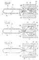
- FIG. 1 There is shown schematically in Figure 1 a bag 10 whose mouth is referenced 12 and the bottom 14.
- the bag 10 is composed of two main sheets 16, 18. These are interconnected at the bottom 14 (by folding, the two sheets 16, 18 being integral with origin as illustrated in FIGS. 1 to 3, or by welding or gluing, the two sheets 16, 18 being initially separated and superimposed during manufacture as illustrated in FIGS. 4 to 9, or by welding or gluing the edges of a single folded sheet on itself at the mouth, as illustrated for example on Figures 10 and 11), as well as at the two lateral edges perpendicular to the bottom 14 and the mouth 12 (the connection at the side edges is preferably provided by welding or gluing).
- the two sheets 16, 18 are provided of complementary closure profiles 20, 22.
- closure profiles 20, 22 respectively of male and female type as is well known from those skilled in the art and as shown schematically in Figures 1 to 3 and 12 and following.
- the invention is not limited to this particular provision and can also extend for example to closure profiles 20, 22 of the hook type as illustrated in figures 4 to 11.
- the profiles additional closure 20, 22 may have come from extrusion on the sheets 16, 18 making up the sachet (more precisely on the inner surface of these sheets 16, 18 according to the embodiments of Figures 1 and 3 to 7 and on the external surface of these sheets according to the embodiment of the Figure 10 when the sheets 16, 18 form, at the mouth of the bag, a bellows folded towards the inside of the bag to form a control veil opening).
- the profiles of closure 20, 22 can be formed initially on support webs respective 21, 23 reported on sheets 16, 18, at the level of the mouth 12 of the bag, as illustrated in FIGS. 2, 8, 9 and 11.
- the support webs 21, 23 are fixed on the internal surface of the sheets 16, 18.
- the sheets 16, 18 forming, at the mouth of the bag, a bellows folded towards the inside of the bag to form an opening veil, the support webs 21, 23 are fixed on the external surface of the sheets 16, 18.
- connection between the webs 21, 23 and the films 16, 18 can be produced by any suitable conventional means, for example by welding hot or sticking.
- closure profiles not from extrusion on films 16, 18, but reported by welding or gluing is not illustrated on the accompanying drawings only in Figures 2, 8, 9 and 11.
- the use such closure profiles 20, 22 attached to the films 16, 18 may apply to all of the variant embodiments in accordance with the invention.
- the bag further comprises on the one hand a slider 50 suitable for actuate the profiles 20, 22 on closing and opening, and on the other hand, parallel to the closure sections 20, 22, between said sheets 16, 18 and at the mouth 12 of the bag, additional means relief 100 designed to ensure sealing by forming a barrier between the sheets 16, 18, in the closed position of the bag, said means additional reliefs 100 being placed opposite the flanks 52, 54 of the cursor 50 to be pressed towards their sealing position by the cursor 50 when the latter is moved to the sealing position.
- a slider 50 suitable for actuate the profiles 20, 22 on closing and opening, and on the other hand, parallel to the closure sections 20, 22, between said sheets 16, 18 and at the mouth 12 of the bag, additional means relief 100 designed to ensure sealing by forming a barrier between the sheets 16, 18, in the closed position of the bag, said means additional reliefs 100 being placed opposite the flanks 52, 54 of the cursor 50 to be pressed towards their sealing position by the cursor 50 when the latter is moved to the sealing position.
- the cursor 50 can be the subject of numerous embodiments classics.
- the cursor 50 may in particular comply with the provisions described in document EP-A-0479661.
- the cursor 50 preferably has two lateral wings 52, 54 (or “sides") interconnected at a base 56 and which define with a elongated central sole (not shown in the figures appended to level of the location of the section plane illustrated) two passage lanes converging for complementary nestable closing profiles 20, 22.
- a elongated central sole not shown in the figures appended to level of the location of the section plane illustrated
- Films 16, 18, closure profiles 20, 22 and the means additional sealing 100 can be made of any material suitable plastic known to those skilled in the art.
- it is polyolefin, very advantageously of low or high density polyethylene, even polypropylene.
- the means 100 are arranged on the inside of the closure profiles 20, 22 (this is say towards the inside of the bags with respect to these closure profiles 20, 22) and extend over the entire length of the sachets (i.e. have the same length as the closure profiles 20, 22).
- said additional sealing means 100 are formed by a bead 102 parallel to the profile 20 and integral with one of the sheets 16. According to FIG. 1 this bead 102 came from extrusion on the film 16. As a variant, however as mentioned above, the bead 102 could have come of extrusion on a support veil attached to this film 16.
- Such a bead 102 is placed opposite the flanks 52, 54 of the cursor 50 and on the inside of these. Thus the bead 102 is stressed in press against the opposite film 18 when the cursor 50 is moved to position closing.
- the geometry of the sections 20, 22, of the means 100 and of the cursor 50 is such that the sides 52, 54 of the cursor 50 impose on the means 100, transverse play (ie perpendicular to the sheets 16, 18) lower than that tolerated for closure profiles 20, 22.
- the thickness L1 means 100 is greater than that L2 defined by the profiles of closure 20, 22 when these are engaged.
- the means sealing 100 are formed by two beads 104, 106 integral respectively of the two films 16 and 18 and placed opposite to come in contact through their tops to form a tight barrier, when they are biased by the sides 52, 54 of the cursor 50.
- the two beads 104, 106 are symmetrical. Alternatively, however, one can provide beads 104, 106 asymmetrical.
- the means sealing 100 are formed of complementary elements 110, 112 male / female integral respectively with the internal surface of the two sheets 16, 18 of the bag. More precisely still according to FIG. 3, the female element 112 is formed by two lips 1120 and 1122 adapted for come to rest respectively on the sides of the male element 110. According to the Figure 3, the two lips 1120, 1122 are symmetrical. However in alternatively, two asymmetrical lips 1120, 1122 can be provided. Through elsewhere the mixed element 110 is generally rounded.
- the sealing means 100 illustrated in FIG. 4 are identical to those of figure 3. However it will be noted that according to figure 4, the cursor 50 has bosses 520 on the internal surface of its sides 52, 54, 540 placed opposite the means 100 to guarantee the solicitation of these last in sealing position, when closing the bag.
- the geometry of such bosses 520, 540 can be the subject of numerous variants. Alternatively, such bosses can be provided on the surface exterior of the walls 16, 18, facing the cursor, or even such bosses on the walls of the bag and other facing bosses on the cursor 50.
- FIG. 5 Another variant embodiment according to FIG. 5 has been illustrated. which the male element 110 has a substantially triangular section. Thanks to this structure, it is guaranteed that the contact between the sides of the male element 110 and the lips 1120 and 1122 is reinforced when the male and female elements 110 and 112 are urged into reconciliation by the cursor 50.
- the two lips 1120 and 1122 of the female element 112 are asymmetrical.
- the lip 1120 located towards the inside of the bag relative to the male element 110 is longer and more flexible than the second lip 1122 located towards the outside from the sachet.
- the internal pressure of the sachet, or even possibly directly the content thereof, such as liquid content requests the first lip 1120 resiliently against the male element 110.
- second lip 1122 resists such an effort and therefore does not deviate of the male element 110.
- the means 100 can come from extrusion on the sheets 16, 18 making up the sachet (more precisely on the internal surface of these sheets 16, 18 according to the modes of realization of FIGS. 1 to 6 and on the external surface of these sheets according to the embodiment of FIG. 10 when the sheets 16, 18 form, at the mouth of the bag, a bellows folded towards the inside of the bag to form an opening control veil).
- the means 100 can be formed initially on respective support webs 121, 123 reported on the sheets 16, 18, at the mouth 12 of the bag, as illustrated in Figures 7 to 9 and 11. Again we note that according to FIGS. 7 to 9, the support webs 121, 123 are fixed to the surface internal of the sheets 16, 18. On the other hand according to FIG. 11, the sheets 16, 18 forming, at the mouth of the bag, a bellows folded towards the inside of the bag to form an opening control veil, the support veils 121, 123 are fixed on the outer surface of the sheets 16, 18.
- connection between the webs 121, 123 and the films 16, 18 can be produced by any suitable conventional means, for example by welding hot or sticking.
- non-extrusion means 100 on the films 16, 18, but reported by welding or gluing is not illustrated in the drawings appended only in FIGS. 7 to 9 and 11. However, the use of such means 100 reported on films 16, 18 could apply to the whole variant embodiments in accordance with the invention.
- FIG. 6 appended An alternative embodiment has been illustrated in FIG. 6 appended according to laquefle there are provided on the one hand notches 160, 180 which open out on the external surface of the bag, respectively opposite the means 100, in this case respectively opposite the female element 112 and the male element 110, and on the other hand ribs 522 and 542 projecting from the internal surface of the sides 52 and 54 of the cursor 50, which ribs 522 and 542 are adapted to penetrate respectively into said notches 160 and 180.
- ribs 522 and 542 and complementary notches 160, 180 are illustrated in the accompanying drawings only in FIG. 6. However, the use of such ribs 522 and 542 and notches 160, 180 may apply to all variants of realization in accordance with the invention.
- FIG. 7 has been described previously. he essentially differs from the embodiments illustrated on the previous figures by the fact that the means 100 are carried by sails respective support 121, 123 reported on sheets 16 and 18, as indicated previously.
- FIG. 8 has been described previously. he essentially differs from the embodiments illustrated on the previous figures by the fact that the means 100 are carried by sails respective support 121, 123 combined with the support webs 21 and 23 of the profiles 20, 22 and reported on sheets 16 and 18, as shown previously.
- the support webs 121, 21 and 123, 23 are interconnected by a loop 24. This is arranged on the inside means 100 and has its concavity directed towards the outside of the sachet.
- these support sails 121, 21, 123, 23 and 24 form an anti-violation veil or opening indicator at mouth 12. effect of breaking this veil 24 before accessing the interior of the bag.
- This veil anti-violation 24 is formed by a bellows folded towards the inside of the sachet, at the level of the mouth 12 in the continuity of the support sails 121, 21 and 123, 23.
- Such a bellows 19 directed towards the inside of the bag can be shaped by any suitable known means, for example using a blade acting the bellows 19 inwards between the sheets 16, 18, as is good known to those skilled in the art.
- condition of the veil 24 or 19 makes it possible to indicate whether an intervention has whether or not occurred on the bag 10.
- the sachets obtained in the context of the present invention offer many advantages compared to known prior sachets.
- notches 160, 180 and the ribs 522, 542 of the sliders 50 makes it possible to avoid any untimely withdrawal sliders 50 under the effect of the internal pressure in the sachets or else under the effect of a solicitation by a user.
- a weld can be provided between the internal surfaces of the main sheets 16, 18 making up the bag and the sections 162, 182 forming the bellows corresponding to the anti-intrusion veil 19 as shown schematically under the reference 60 in the figures 10 and 11.
- the bags according to the present invention can be produced on all types of known and appropriate machines, in particular on FFS (Form, Fill and Seal) type machines, i.e. machines designed to carry out training operations automatically, filling and closing of sachets.
- FFS Form, Fill and Seal
- the present invention applies equally well to in which the closure profiles are arranged longitudinally with reference to the direction of travel of the film only at implementations according to which the closure profiles are arranged transversely.
- the present invention is equally applicable to implementations work according to which, the closing profiles are pre-equipped with slider when fed to the bag forming machine, than implementations where the cursor is arranged later on the profiles.
- notches 160, 180 and ribs 522, 542 illustrated on the Figure 6 attached.
- these notches 160, 180 and ribs 522, 542 can be the subject of numerous variant embodiments as to their straight section. So for example we can consider giving notches 522, 542 a cross section with converging edges, for example in dovetail or rail-shaped (e.g. T-shaped or others). Such a provision reinforces the retention of the cursor 50 on the sachets.
- the sealing means 100 and the profiles of closure 20, 22 extend over the entire width of the bag.
- the cursor 50 only extends over a limited area of this width. Consequently, the cursor 50 cannot alone solicit the sealing means 100 permanently over their entire length.
- the closure profiles 20, 22 are adapted to automatically secure such a request P means 100 when the bag is closed.
- the element internal 220 of the female profile 22 induces a constraint on the means sealing 100 in the closed state of the bag, that is to say when the element male 20 is engaged with the female element 22 and this over the entire length means 100.
- the two additional hooks C1, C2 located towards the inside of the bag define in the assembled position a width L5 between the internal faces sheets 16, 18 less than the width L6 taken between the same faces sheets 16, 18 at the pair of complementary hooks C3, C4 located towards the outside of the bag. This provision ensures the same constraint over the entire length of the means 100.
- FIG. 12 An alternative embodiment has been illustrated in FIG. 12 according to which the two elements 104, 106 respectively secured to the internal surface sheets 16, 18 are not positioned to bear by their vertex, as indicated previously with regard to FIG. 2, but are positioned to be juxtaposed and come to rest at their sides adjacent opposite 103, 105 generally perpendicular to the sheets 16 and 18.
- the cursor 50 is provided on the ends of its lateral wings 52, 54, of respective returns 53, 55 directed inwards from the sachet.
- These returns 53, 55 are positioned to be located beyond the sealing means 100.
- these returns 53, 55 participate in the tightness of the bag.
- these returns 53, 55 participate in the keeping the cursor 50 on the sachets to prevent an untimely withdrawal cursor.
- these returns 53, 55 request the sheets 16, 18 in approach, beyond the sealing means 100.
- the portions of support films 16, 18 located opposite the closure profiles 20, 22 and the means sealing 100 have a thickness greater than the thickness of the rest of the film making up the sachet.
- This extra thickness of the support films 16, 18 to the right of the cursor 50 makes it possible to maintain the means 100 in their sealing position when the bag is in the closed position.
- Such a localized excess thickness of the films 16, 18 can be obtained in the form of a excess thickness formed during extrusion of the film or else may result from the fixing of supporting webs of closure profiles 20, 22 or of the means 100, as previously indicated.
- FIG. 13 Another variant embodiment according to FIG. 13 has been illustrated. which the two elements 104, 106 respectively fixed to the surface internal of the sheets 16, 18 are provided at their top with a respective wing 1040, 1060 orthogonal audits elements.
- said wings 1040, 1060 generally extend parallel to the sheets 16, 18.
- the elements 104, 106 are supported at their apex by means of these wings 1040, 1060.
- said wings 1040, 1060 are directed towards the inside of the bag.
- the wings 1040, 1060 are on the contrary directed towards the outside of the bag.
- such wings 1040, 1060 can be provided on the vertex of elements 104, 106 both inward and outward of the bag.
- the elements 104, 106 provided with the wings 1040, 1060 have the general shape of a T.
- FIG. 14 12 An alternative embodiment of the figure is illustrated in FIG. 14 12 according to which at least one of the two juxtaposed elements 104, 106 is fitted at its top with an orthogonal 1060 wing. This one is intended for come to rest against the internal face of the opposite sheet 16 to perfect sealing. According to Figure 14 there is shown such a wing 1060 on one only elements 106. As a variant, it is however possible to provide a such additional wing intended to come to rest against the internal face of the opposite sheet, on the top of the two elements 104, 106.
- FIG. 15 illustrates another alternative embodiment of the Figure 12 according to which the two juxtaposed elements 104, 106 are provided at their apex with a rounded outgrowth 1042, 1062. This is intended to come to rest against the internal face of the sheet 16, 18 opposite to complete the seal. According to Figure 15, there is provided such protuberance on the two elements 104, 106. As a variant, it is possible to provide such a protrusion 1042, 1062 on a single element 104, 106. According to the Figure 15, these growths have a circular cross section and are symmetrical with respect to the median plane of the elements 104, 106. However the invention is not limited to this particular geometry.
- FIG. 16 13 An alternative embodiment of the figure is illustrated in FIG. 16 13 according to which the cursor 50 is further provided at the ends from each of the returns 53, 55 from an additional wing 530, 550 directed towards the base 56 of the cursor 50, that is to say towards the outside of the bag.
- These wings 530, 550 are thus oriented generally parallel to the lateral wings 52, 54 of cursor 50.
- These additional wings 530, 550 are designed to take position in the volume defined between sheets 16, 18 and 1040, 1060 sealing means 100. It is understood on examination of the figure 16 that these wings 530, 550 ensure an undulation on the sheets 16, 18 suitable for further strengthening the tightness of the bags obtained.
- the cursor 50 has symmetry with respect to a longitudinal plane. So according to Figures 12 to 14, each of the sides 52, 54 is provided with a return 53, 55.
- the cursor exhibits an asymmetry in the sense that only one 52 of the flanks is provided of such a return 53 directed towards the inside of the bag.
- FIG. 18 17 An alternative embodiment of the figure is illustrated in FIG. 18 17 according to which this return 53 is provided on its internal surface with a boss 532 directed towards the base 56 to urge the two juxtaposed elements 104, 106 supported by their adjacent sides 103, 105.
- the boss 532 exerts on the element 104 a directed stress to base 56.
- FIG. 19 Another variant embodiment according to FIG. 19 has been illustrated. which the portions of supporting films 16, 18 carrying the profiles of closure 20, 22 and the sealing means 100 are not located in the direct extension of the leaves making up the body of the sachet, but are shifted towards the outside of the bag at the respective recesses 1600, 1800. These 1600, 1800 recesses can be obtained by extrusion during the manufacture of the film or be obtained subsequently by folding of the film. It will be understood on examining FIG. 19 that such recesses 1600, 1800 make it easier to juxtapose the sheets 16, 18 at the exit of cursor 50, although sheets 16, 18 are necessarily separated, inside the cursor due to the presence closure profiles 20, 22 and means 100.
- one of the 1800 recesses can itself be provided with an extension 1802 directed towards the opposite support sheet 16.
- This extension 1802 is designed to come to rest against the opposite recess 1600 so the further strengthen the tightness of the bags obtained.
- FIG. 20 illustrates an alternative embodiment according to which on the one hand there is a boss 530 or return towards the interior of the cursor on the single return 53 and on the other hand an element 106 projecting from the sheet 18.
- the boss 530 imposes a bending or labyrinth path to the second sheet 16 at the outlet of the cursor 50, which is again suitable for strengthening the tightness of the sachet obtained.
- FIG. 21 12 An alternative embodiment of the figure is illustrated in FIG. 21 12 according to which at least one of the two elements 104 or 106 has a increasing thickness towards its apex or has a flank inclined so that it exerts a force on the other element 106 or 104 juxtaposed, in the closed position of the bag.
- FIGS. 22 We have illustrated in FIGS. 22 and following variants of embodiment according to which the sealing means 100 are formed essentially flexible and elastic structures, to be deformable when closing the bag, while according to the representations given in FIGS. 12 to 21, the means 100 are essentially rigid.
- FIG. 22 An alternative embodiment according to FIG. 22 has thus been illustrated. which the sealing means 100 comprise a curved lip, flexible and elastic 130 secured to the sheet 18 carrying the profile of female closure 22.
- such a flexible and elastic lip 130 could be integral with the sheet 16 which carries the male closure profile 20.
- the lip 130 is formed of a cylinder sector whose angle in the center is greater than 180 °. According to Figure 22, the concavity of the lip 130 is directed towards the inside of the bag. Alternatively however provision could be made for the concavity of the lip 130 to be directed towards the outside of the bag.
- FIG. 24 22 An alternative embodiment of the figure is illustrated in FIG. 24 22 that the location of the lip 130 and the geometry of this lip 130 are such as said lip 130, when it rests on the sheet 16 opposite, receives a reaction which requests it itself in support against one closure profiles, in this case the female closure profile 22.
- FIG. 25 Another variant embodiment according to FIG. 25 has been illustrated. which such a biasing of the lip 130 bearing against the element of female closure 22 is reinforced by the presence on the internal surface flanks 52, 54 of the boss cursor 50 520, 540.
- these bosses 520, 540 have a profile general triangular.
- these bosses 520, 540 are not limited to this geometry and can be the subject of numerous variants of production.
- FIG. 26 Illustrated in Figure 26 is a side view of a bag as well team.
- a cursor 50 having such stressing bosses 520, 540, as well as closing profiles 20, 22 and the sealing means 100.
- the bosses 520, 540 extend only over part of the length of the cursor 50 and also converge towards the upper base 56 of cursor 50 near the end of cursor 50 on the side opening of the bag. Thanks to this arrangement, the bosses 520, 540 stress the lip 130 in abutment against the closure profile 22, in the vicinity of the bag opening area.
- the returns 53, 55 provided on the wings 52, 54 of the cursor 50 can converge on the base 56 near the end of the cursor 50 located on the side of the sachet opening, to improve the tightness of the bag at this level.
- each of the two sheets 16, 18 is provided on its internal surface of an elastic lip 130 in the cylinder sector. These two lips 130 are thus resting on their top when the bag is closed.
- At rest that is to say in the open position, at least one of the two lips 130 preferably extends beyond the profile associated closure, as shown diagrammatically in FIG. 28.
- the cursor 50 used in the context of the alternative embodiment of the figure 27 can also include stressing bosses 520, 540 ascending, as illustrated in figure 26, to solicit these lips elastic 130 against the closing profiles 20, 22, in the bag closure.
- each of the two support films 16, 18 is provided with a lip elastic 130, but however these are positioned not for come to rest by their top, but to be juxtaposed laterally as seen in FIG. 29.
- the two lips 130 formed each of a cylinder sector having an angle at the center greater than 180 ° have their concavity directed inward and inward respectively the outside of the bag.
- the sachet has on its mouth 12, means 150 located opposite said additional sealing means 100, relative to the profiles of closure 20, 22, and these means 150 are adapted to define a support between the opposite internal faces of the walls of the bag.
- the cursor 50 means capable of urging the walls of the sachet, towards inside, in an area of these walls between the means additional sealing 100 and the support means 150. This guarantees that said additional means 100 are solicited in a position sealing, by the slider 50. Preferably this request is made to the right of closing profiles 20 and 22.
- the additional sealing means 100 are located on the inside of the profiles closing 20, 22, while the means 150 defining the support are located on the outside of the closure sections 20, 22.
- This arrangement comprising means 150 associated with biasing means of the sealing means 100 by the cursor 50, can apply to all of the variants previously described. They are therefore not limited to the embodiments of the figures 30 to 39. In particular this provision applies to all types of means 100, all types of closure profiles 20, 22 and all slider variants 50 or bag equipped with an anti-veil veil, etc ...
- FIG. 30 A variant has been illustrated in FIG. 30 according to which the means additional sealing 100 are formed by two flexible lips and elastic 170, 172, symmetrical and integral respectively with the face internal walls 16 and 18, and directed towards the inside and the bottom of the bag.
- these lips 170, 172 can be directed towards the inside of the cursor 50 (especially for example for vacuum bags).
- the provision of support means 150 applies to all types 100 sealing means and is not limited to the means 100 of the figure 30. It can in particular be applied to lips 170, 172 not symmetrical.
- closure profiles 20, 22 are of male / female type.
- the invention can be applied to any other type closing profiles, in particular hook profiles.
- the support means 150 are formed of two symmetrical elements 152, 154, respectively fixed to the faces internal walls 16, 18, at the mouth of the bag. More again precisely according to FIG. 30, each of these elements 152, 154 has a rectangular cross section and extends towards the plane median of the bag at which these elements are in mutual support, in closed position of the bag. Thus these elements 152 and 154 extend generally perpendicular to this median plane.
- the means 100, the sections 20, 22 and the means 150 have come from material, if necessary from material, from preferably from extrusion, with walls 16, 18. More precisely again it will be noted that the sections of these walls comprised between the means sealing 100 and the support means 150 are thicker than the sheets 16, 18 making up the rest and most of the sachets. So the sections above have a certain rigidity between the means 100 and the means 150.
- FIG. 31 illustrates the biasing means provided on the slider 50, in the form of bosses 520, 540 provided on the internal surface wings 52, 54, in line with the closure profiles 20, 22.
- This is here bosses formed by cylindrical caps, but the invention is not limited to this particular geometry.
- the aforementioned sections define at the mouth of the bag a cross-section cage rectangular which projects from the main walls 16 and 18 of the bag.
- the main walls of the bag are not coplanar with the external surfaces of these sections, but set back inward, relative to them, of a value "d". It is thus defined on the walls 16 and 18 of the bag a recess which serves to support the returns 53 and 55 provided on the wings 52 and 54 of the cursor 50, to avoid a untimely withdrawal of it.
- the aforementioned sections, between the means 100 and 150, define at the mouth of the sachet not a rectangular cross section cage, but a cage globally rounded.
- the elements support 152, 154 are symmetrical and contact each other in the median plane of the bag. Alternatively, however, these elements 152, 154 may be asymmetrical and thus contact each other outside the median plane. So we have illustrated in FIG. 34, a variant according to which only the wall 18 is provided with a support element 154 projecting from its internal face. This element 154 is adapted to come to rest on the internal face of the opposite wall 16.
- the means sealing 100, the closing profiles 20, 22 and the support means 150 came from material, if any material, preferably from extrusion, on the walls 16, 18.
- these different means may have come on respective support sails, by example thermally welded or glued to the inner sides of the sheets 16, 18.
- These can be respective and separate support sails for each means 100, profiles 20, 22 and means 150, or even sails supports common to several of these means.
- FIG. 35 an alternative embodiment according to which the means 100, the closure profiles 20, 22 and the support means 150 are carried by two respective sails, one attached to the internal face of the sheet 16, and reported the other on the internal face of the sheet 18.
- FIG. 36 An alternative embodiment has been illustrated in FIG. 36 according to which the biasing means are formed not of bosses integral with the inner face of the wings of the cursor, but of bosses 15 projecting from the external face of the wall sections situated between the means 100 and 150, of in preference to the closure profiles 20, 22. According to yet another variant it is thus possible to provide bosses both on the cursor and on the walls of the bag.
- FIG. 37 Another variant embodiment according to FIG. 37 has been illustrated. which the opposite ends of the elements 152 and 154 forming means are widened, to guarantee their support and prevent these elements, by offset do not find themselves adjacent, in which case the arm of expected lever to exercise the solicitation on the means 100 would not got.
- the adjacent ends of the elements 152 and 154 have a generally triangular cross section with a base located in the contact plane.
- the invention is not limited to this special provision.
- FIG. 38 A variant has been illustrated in FIG. 38 according to which the cursor 50 is fitted on the inner face of its wings 52, 54 with projecting structures 522, 542 of complementary cross section of grooves 13 formed in the aforementioned bosses 15, the structures 522 and 542 being engaged in these grooves 13. More precisely still, the structures 522, 542 are flared, while the grooves 13 have converging edges. Thanks to that provision is avoided an untimely withdrawal of the cursor 50.
- FIG. 39 Another variant embodiment according to FIG. 39 has been illustrated. which it is thus defined means with complementary forms violates the cursor 50 and the walls of the bag, at the returns 53, 55 formed on the wings 52, 54, in the form of elements 530, 550 as described previously.
- the elements making up the sealing means 100 can be coextruded with the bag and / or the closure profiles, a more flexible material than the material forming the latter.
- sealing means in the context of the present invention that the means 100 are adapted (according to their geometry and / or their strength support) or to ensure a complete barrier preventing any penetration from the outside to the inside of the bag and any leakage from the inside to the outside of the bag, either to ensure at least one barrier in one direction, ie to prohibit penetration from the outside towards the inside of the bag, or prohibit a leak from the inside to the outside of the bag.
- the means sealing 100 may not be placed opposite the sides 52, 54, of the cursor, but outside of it. In other words, in this case, the end of the cursor is located between these means 100 and the profiles of closing 20, 22.
- the sole 59 is interrupted below (that is to say behind) the end longitudinal of the cursor, at least on the widest side of the cursor corresponding to the divergent side of the lanes 590, 592, as seen in particular in FIGS. 40, 42, 43 and 44, and the lateral wings 52, 54 are provided near their free edge opposite the base 56, means 520, 540 for soliciting sheets 16, 18 of the sachet in reconciliation, covering the entire longitudinal extent of the sole 59 and extending beyond longitudinally on either side of it, to ensure the watertightness of the sachet in the closed position thereof.
- these biasing means are composed of ribs 520, 540 in inward projection of the cursor 50, at the edge of the wings 52, 54 opposite the base 56, or where appropriate over part of the height of the internal surface of these wings 52, 54 lying between the free edge of the wings 52, 54 and the base 56. It will be noted that if the ribs 520, 540 are not necessarily located at the free edge of the lateral wings 52, 54, these ribs 520, 540 are however located below the sole 59 (that is to say between the top of the sole 59, opposite the base 56, and the free edge of the wings 52, 54), and not at the height thereof.
- ribs 520, 540 continuously cover the sole 59 and extend beyond it, at least at the most wide of the sole 59 corresponding to the divergent side of the corridors 590, 592. More precisely still, according to the preferred embodiment illustrated in the appended figures, the ribs 520, 540 extend over all the length of the slider 50, while the sole 59 is interrupted, at the level of its widest end (divergent side of the corridors 590, 592), at a distance I1 from the end of the cursor 50, and at its level thinner end (converging side of lanes 590, 592), one distance I2 from the end of the cursor 50.
- the width 16 of the free space defined between the vertices of the ribs 520, 540 is substantially equal to the sum of the thicknesses of the sheets 16, 18, at the mouth of the sachets. So the cursor 50 solicits the sheets in approach, below the sole 59, and guarantees the tightness of the sachet.
- two symmetrical ribs 520, 540 are provided and likewise height, one on each of the wings 52, 54.
Landscapes
- Engineering & Computer Science (AREA)
- Mechanical Engineering (AREA)
- Bag Frames (AREA)
- Slide Fasteners (AREA)
- Making Paper Articles (AREA)
Claims (105)
- Beutel, der zwei im allgemeinen parallele Bogen (16, 18), die die Hauptwände des Beutels bilden, komplementäre Schließprofile(20, 22), die jeweils auf diesen Bogen befestigt sind, und einen Schieber (50) aufweist, um die Profile (20; 22) beim Schließen and beim Öffnen zu betätigen, dadurch gekennzeichnet, daß er außerdem parallel zu den Schließprofilen (20, 22) zwischen den genannten Bogen (16, 18) und auf Höhe der Mündung (12) des Beutels zusätzliche, erhabene Mittel (100) auf der Innenoberfläche mindestens eines Bogens des Beutels zur Innenseite des Beutels hin aufweist, auf die Schließprofile (20, 22) bezogen, die dazu konzipiert sind, die Abdichtung sicherzustellen, indem sie eine Sperre zwischen den Bogen (16, 18) in der Schließposition des Beutels bilden, wobei die genannten, zusätzlichen, erhabenen Mittel (100) dazu eingerichtet sind, zu ihrer Dichtlage hin durch den Schieber (50) belastet zu werden, wenn der Schieber in Richtung der Schließlage des Beutels versetzt wird.
- Beutel nach Anspruch 1, dadurch gekennzeichnet, daß die zusätzlichen, erhabenen Mittel (200), die die Abdichtung sicherstellen, aus mindestens einem Wulst (102; 104, 106) zisammengesetzt sind, der mit der Innenoberfläche eines Bogens (16) des Beutels fest verbunden ist.
- Beutel nach einem der Ansprüche 1 oder 2, dadurch gekennzeichnet, daß die zusätzlichen, erhabenen Mittel (100), die die Abdichtung sicherstellen, aus zwei Wülsten (104, 106) zusammengesetzt sind, die jeweils mit der Innenoberfläche der beiden Bogen (16, 18) des Beutels verbunden sind.
- Beutel nach Anspruch 1, dadurch gekennzeichnet, daß die zusätzlichen, erhabenen Mittel (100), die die Abdichtung sicherstellen, auskomplementären Vater-/Mutterelementen (110, 112) zusammengesetzt sind, die jeweils fest mit der Innenoberfläche der beiden Bogen (16, 18) verbunden sind.
- Beutel nach Anspruch 4, dadurch gekennzeichnet, daß das Vaterelement (110) einen im wesentlichen dreieckigen Querschnitt darbietet.
- Beutel nach einem der Ansprüche 4 oder 5, dadurch gekennzeichnet, daß die beiden Lippen (1120 und 1122) des Mutterelements (112) unsymmetrisch sind.
- Beutel nach einem der Ansprüche 4 bis 6, dadurch gekennzeichnet, daß die Lippe (1120) des Mutterelements (112), die, bezogen auf das Vaterelement (110), zur Innenseite des Beutels hin gelegen ist, länger und weicher ist als die zweite Lippe (1122), die zur Außenseite des Beutels hin gelegen ist.
- Beutel nach einem der Ansgrüche 1 bis 7, dadurch gekennzeichnet, daß die zusätzlichen, erhabenen Mittel (100), die die Abdichtung sicherstellen, sich über die gesamte Länge,der Beutel erstrecken.
- Beutel nach einem der Ansprüche 1 bis 8, dadurch gekennzeichnet, daß die Geometrie der Profile (20, 22), der zusätzlichen Mittel (100) und des Schiebers (50) so ist, daß die Flanken (52, 54) des Schiebers (50) den Mitteln (100) ein Spiel in Querrichtung auferlegen, das kleiner ist als das, das für die Schließprofile (20, 22) toleriert wird.
- Beutel nach einem der Ansprüche 1 bis 9, dadurch gekennzeichnet, daß die Innenoberflächen der Flanken (52, 54) des Schiebers (50) parallel sind, und daß die Dicke (L1) der Mittel (100) größer ist als die (L2), die durch die Schließprofile (20, 22) definiert wird, wenn diese sich in Eingriff befinden.
- Beutel nach einem der Ansprüche 1 bis 10, dadurch gekennzeichnet, daß der Schieber (50) auf der Innenoberfläche seiner Flanken (52, 54) Höcker (520, 540) besitzt, die den Mitteln (100) gegenüberliegend angeordnet sind, um die Belastung dieser letztgenannten in der Dichtungsposition während des Schließens des Beutels zu garantieren.
- Beutel nach einem der Ansprüche 1 bis 11, dadurch gekennzeichnet, daß die Wände des Beutels Höcker aufweisen, die den Mitteln (100) gegenüberliegend und den Flanken des Schiebers (50) gegenüberliegend angeordnet sind, um die Belastung der Mittel (100) in der Dichtungsposition während des Schließens des Beutels zu garantieren.
- Beutel nach einem der Ansprüche 1 bis 12, dadurch gekennzeichnet, daß er einerseits Vertiefungen (160, 180) aufweist, die auf der Außenoberfläche des Beutels jeweils den Mitteln (100) gegenüberliegend einmünden, und andererseits Rippen (522 und 542), die auf der Innenseite der Flanken (52 und 54) des Schiebers (50) vorspringen, wobei diese Rippen (522 und 542) dazu eingerichtet sind, um in die genannten Vertiefungen (160 und 180) jeweils einzudringen.
- Beutel nach einem der Ansprüche 1 bis 13, dadurch gekennzeichnet, daß er Mittel (19, 24) aufweist, die aüf der Höhe der Mündung (12) eine Unverletztheitsabdeckung oder einen Offnungsnachweis bilden.
- Beutel nach Anspruch 14, dadurch gekennzeichnet, daß die Unverletztheitsabdeckung (24) aus einem auf Höhe der Mündung (12) durchgehend über die tragenden Abdeckungen (121, 21 und 123, 23) der Schließprofile oder der zusätzlichen Abdichtungsmittel zur Innenseite des Beutels eingebogenen Balgen gebildet ist.
- Beutel nach Anspruch 14, dadurch gekennzeichnet, daß die Unverletztheitsabdeckung (19) aus einem auf Höhe der Mündung (12) durchgehend über die den Beutel zusammensetzende Folie zur Innenseite des Beutels eingebogenen Balgen gebildet ist.
- Beutel nach einem der Ansprüche 1 bis 16, dadurch gekennzeichnet, daß der Beutel (10) aus einer einzigen Folie gebildet ist, die auf Höhe des Bodens (14) des Beutels auf sich selbst umgebogen ist.
- Beutel nach einem der Ansprüche 1 bis 16, dadurch gekennzeichnet, daß der Beutel (10) aus einer einzigen Folie gebildet ist, die auf Höhe der Mündung (12) des Beutels auf sich selbst umgebogen ist.
- Beutel nach einem der Ansprüche 1 bis 16, dadurch gekennzeichnet, daß der Beutel (10) aus zwei Folien (16, 18) gebildet ist, die anfänglich getrennt und bei der Herstellung übereinandergelegt sind.
- Beutel nach einem der Ansprüche 1 bis 19, dadurch gekennzeichnet, daß die komplementären Schließprofile (20, 22) und/oder die zusätzlichen Abdichtungsmittel (100) der Extrusion auf den Bogen (16, 18) entstammen, die den Beutel zusammensetzen.
- Beutel nach einem der Ansprüche 1 bis 19, dadurch gekennzeichnet, daß die komplementären Schließprofile (20, 22) und/oder die zusätzlichen Abdichtungsmittel (100) anfänglich auf den jeweiligen Abdeckungen (21, 23; 121, 123) auf den Bogen (16, 18) auf Höhe der Mündung (12) des Beutels aufgesetzt sind.
- Beutel nach einem der Ansprüche 1 bis 19 und 21, dadurch gekennzeichnet, daß die komplementären Schließprofile (20, 22) und/oder die zusätzlichen Abdichtungsmittel (100) anfänglich auf den gemeinsamen, tragenden Abdeckungen (21, 23; 121, 123) ausgebildet sind, die auf den Bogen (16, 18) auf Höhe der Mündung (12) des Beutels aufgesetzt sind.
- Beutel nach einem der Ansprüche 1 bis 22, dadurch gekennzeichnet, daß die Schließprofile (20, 22) dazu eingerichtet sind, automatisch eine Querbelastung (P) auf die Mittel (100) sicherzustellen, wenn der Beutel geschlossen ist.
- Beutel nach einem der Ansprüche 1 bis 23, dadurch gekennzeichnet, daß die komplementären Schließprofile (20, 22) der Art nach Vater- bzw. Mutterteile sind, und daß sie mindestens ein unsymmetrisches Vater- oder Mutterprofil aufweisen.
- Beutel nach Anspruch 24, dadurch gekennzeichnet, daß die Höhe oder die Abmessungen (L3) des Elements (220), das die innere Lippe des Mutterprofils (22) definiert, kleiner ist als die Höhe oder die Abmessungen (L4) des Elements (222), das die äußere Lippe des Mutterprofils (22) definiert.
- Beutel nach einem der Ansprüche 1 bis 23, dadurch gekennzeichnet, daß die komplementären Schließprofile (20, 22) hakenartig sind, und daß sie mindestens zwei Paare komplementärer Haken besitzen, die in der zusammengefügten Lage Breiten besitzen, die sich von einem Hakenpaar zu einem anderen unterscheiden.
- Beutel nach Anspruch 26, dadurch gekennzeichnet, daß die beiden komplementären Haken (C1, C2), die zur Innenseite des Beutels hin gelegen sind, in der zusammengefügten Lage eine Breite (L5) zwischen den inneren Flächen der Bogen (16, 18) definieren, die kleiner ist als die Breite L6, die zwischen denselben Flächen der Bogen (16, 18) auf Höhe des Paares komplementärer Haken (C3, C4) vorliegt, die zur Außenseite des Beutels hin gelegen sind.
- Beutel nach einem der Ansprüche 1 bis 27, dadurch gekennzeichnet, daß die zusätzlichen, erhabenen Mittel (100), die die Abdichtung sicherstellen, aus zwei Elementen (104, 106) zusammengesetzt sind, die jeweils mit der Innenfläche der beiden Bogen (16, 18) des Beutels fest verbunden sind und dazu bestimmt sind, durch ihren Scheitel in Auflage zu kommen.
- Beutel nach einem-der Ansprüche 1 bis 27, dadurch gekennzeichnet, daß die zusätzlichen, erhabenen Mittel (100), die die Abdichtung sicherstellen, aus zwei Elementen (104, 106) zusammengesetzt sind, die mit der Innenoberfläche jeweils der beiden Bogen (16, 18) des Beutels fest verbunden sind und dazu bestimmt sind, nebeneinandergelegt zu werden und auf der Höhe ihrer benachbarten, gegenuberliegenden Flanken (103, 105) insgesamt senkrecht zu den Bogen (16, 18) in Auflage zu gelängen.
- Beutel nach einem der Ansprüche 1 bis 27, dadurch gekennzeichnet, daß der Schieber (50) auf den Enden mindestens eines seiner seitlichen Flügel (52, 54) mit einer Umkehrung (53, 55) versehen ist, die der Innenseite des Beutels zugewandt ist und so angeordnet ist, daß sie jenseits der Abdichtungsmittel (100) gelegen ist.
- Beutel nach Anspruch 30, dadurch gekennzeichnet, daß der Schieber (50) außerdem auf Hähe des Endes dieser Umkehrung (53, 55) mit einem zusätzlichen Flügel (530, 550) versehen ist, der dem Sockel (56) des Schiebers (50) zugewandt ist, das heißt zur Außenseite des Beutels hin.
- Beutel nach einem der Ansprüche 1 bis 31, dadurch gekennzeichnet, daß die Teile der tragenden Folien (16, 18), die den Schließprofilen (20, 22) gegenüberliegend gelegen sind, und die Abdichtungsmittel (100) eine Dicke besitzen, die größer ist als die Dicke des Restes der Folie, die den Beutel zusammensetzt.
- Beutel nach Anspruch 32, dadurch gekennzeichnet, daß die örtliche Überdicke der Folien (16, 18) in Form einer Überdicke erhalten wird, die bei der Extrusion der Folie gebildet wird.
- Beutel nach Anspruch 32, dadurch gekennzeichnet, daß sich die örtliche Überdicke der Folien (16, 18) aus der Befestigung von tragenden Abdeckungen der Schließprofile (20, 22) oder der Mittel (100) ergibt.
- Beutel nach einem der Ansprüche 3 und 28, dadurch gekennzeichnet, daß die beiden Elemente (104, 106), die jeweils mit der Innenoberfläche der Bogen (16, 18) fest verbunden sind, an ihrem Scheitel mit mindestens einem jeweiligen, zu den genannten Elementen senkrechten Flügel (1040, 1060) versehen sind.
- Beutel nach einem der Ansprüche 3 und 29, dadurch gekennzeichnet, daß das mindestens eine der beiden Elemente (104, 106), die auf den tragenden Bogen vorgesehen sind, an seinem Scheitel mit einem senkrechten Flügel (1060) versehen ist, der dazu bestimmt ist, zur Anlage gegen die innere Fläche des gegenüberliegenden Bogens (16) zu gelangen.
- Beutel nach einem der Ansprüche 3 und 29, dadurch gekennzeichnet, daß das mindestens eine der beiden Elemente (104, 106), die auf den tragenden Bogen vorgesehen sind, am seinem Scheitel mit einer abgerundeten Ausstülpung (1042, 1062) versehen ist.
- Beutel nach Anspruch 31, dadurch gekennzeichnet, daß der Schieber (50) außerdem auf Höhe des Endes dieser Umkehrung (53, 55) mit einem Hocker (532) versehen ist, der dem Sockel (56) zugewandt ist, um die beiden, nebeneinandergelegten Elemente (104, 106) mittels ihrer benachbarten Flanken (103, 105) in Anlage zu drücken.
- Beutel nach einem der Ansprüche 1 bis 38, dadurch gekennzeichnet, daß die Abschnitte der tragenden Folien (16, 18), die die Schließprofile (20, 22) und die Abdichtungsmittel (100) tragen, nicht in der unmittelbaren Verlängerung der Bogen gelegen sind, die den Körper des Beutels zusammensetzen, sondern zur Außenseite des Beutels hin auf Höhe jeweiliger Verschiebungen (1600, 1800) versetzt sind.
- Beutel nach Anspruch 39, dadurch gekennzeichnet, daß die eine der Verschiebungen (1800) ihrerseits mit einer Verlängerung (1802) versehen ist, die der gegenuberliegenden, tragenden Folie (16) zugewandt ist.
- Beutel nach einem der Ansprüche 3 und 29, dadurch gekennzeichnet, daß mindestens das eine der beiden Elemente (104 oder 106) eine Dicke aufweist, die in Richtung seines Scheitels zunimmt, oder eine Flanke aufweist, die derart geneigt ist, daß sie eine Kraft auf das andere, danebenliegende Element (106 oder 104) in der Schließposition des Beutels ausubt.
- Beutel nach einem der Ansprüche 1 bis 41, dadurch gekennzeichnet, daß die Abdichtungsmittel (100) weiche und elastische Strukturen aufweisen, um während des Schließens des Beutels verformbar zu sein.
- Beutel nach einem der Ansprüche 1 bis 42, dadurch gekennzeichnet, daß die Abdichtungsmittel (100) mindestens eine gekrümmte, weiche und elastische Lippe (130) aufweisen, die fest mit dem Bogen (18) verbunden ist, der eines der Schließprofile (22) trägt.
- Beutel nach Anspruch 43, dadurch gekennzeichnet, daß die Lippe (130) aus einem Zylindersektor gebildet ist, dessen Winkel in der Mitte größer als 180° ist.
- Beutel nach einem der Ansprüche 43 oder 44, dadurch gekennzeichnet, daß in offenem Zustand des Beutels die genannte Lippe (130) sich bis jenseits des zugeordneten Schließprofils (22) derart erstreckt, daß in geschlossenem Zustand des Beutels die genannte Lippe (130) einen Druck auf den gegenüberliegenden Bogen (16) ausübt.
- Beutel nach einem der Ansprüche 43 bis 45, dadurch gekennzeichnet, daß die Stelle der Lippe (130) und die Geometrie dieser Lippe (130) derart sind, daß die genannte Lippe (130), wenn sie auf dem gegenüberliegenden Bogen (16) ruht, eine Gegenkraft aufnimmt, die sie in Andruck gegen eines der Schließprofile drückt.
- Beutel nach Anspruch 46, dadurch gekennzeichnet, daß die Belastung der Lippe (130) zur Anlage gegen das Mutter-Schließelement (22) verstärkt wird durch die Anwesenheit eines Höckers (520, 540) auf der Innenoberfläche der Flanken (52, 54) des Schiebers (50).
- Beutel nach Anspruch 47, dadurch gekennzeichnet, daß die Höcker (520, 540) gegen den oberen Sockel (56) des Schiebers (50) zusammenlaufen, wobei sie sich dem Ende des Schiebers (50) annähern, das auf der Öffnungsseite des Beutels gelegen ist.
- Beutel nach einem der Ansprüche 1 bis 48, dadurch gekennzeichnet, daß jeder der beiden Bogen (16, 18) auf seiner inneren Oberfläche mit einer elastischen Lippe (130) aus einem Zylindersektor versehen ist, die dazu konzipiert sind, um in Anlage durch ihren Scheitel während des Schließens des Beutels zu gelangen.
- Beutel nach einem der Ansprüche 1 bis 48, dadurch gekennzeichnet, daß jeder der beiden Bogen (16, 18) auf seiner Innenoberfläche mit einer elastischen Lippe (130) aus einem Zylindersektor versehen ist, die dazu konzipiert sind, um seitlich nebeneinandergelegt zu werden.
- Beutel nach einem der Ansprüche 1 bis 50, dadurch gekennzeichnet, daß er auf seiner Mündung (12) Mittel (150) aufweist, die den genannten zusätzlichen Abdichtungsmitteln (100), auf die Schließprofile (20, 22) bezogen, gegenüberliegen und dazu eingerichtet sind, eine Auflage zwischen den gegenüberliegenden Innenflächen der Wände des Beutels zu bilden, und auf dem Schieber (50) Mittel (520, 540) vorgesehen sind, die dazu eingerichtet sind, die Wände des Beutels nach innen hin in einer Zone dieser Wände zu belasten, die zwischen den zusätzlichen Abdichtungsmitteln (100) und den Auflagemitteln (150) liegt.
- Beutel nach Anspruch 51, dadurch gekennzeichnet, daß die Belastung längs der Schließprofile (20, 22) bewirkt wird.
- Beutel nach einem der Ansprüche 51 oder 52, dadurch gekennzeichnet, daß die zusätzlichen Abdichtungsmittel (100) auf der Innenseite der Schließprofile (20, 22) gelegen sind, während die Mittel (150), die die Auflage definieren, auf der Außenseite der Schließprofile (20, 22) gelegen sind.
- Beutel nach einem der Ansprüche 51 bis 53, dadurch gekennzeichnet, daß die zusätzlichen Abdichtungsmittel (100) aus zwei weichen und elastischen Lippen (170, 172) gebildet sind.
- Beutel nach einem der Ansprüche 51 bis 54, dadurch gekennzeichnet, daß die Auflagemittel (150) aus zwei Elementen (152, 154) gebildet sind, die auf Höhe der Mündung des Beutels jeweils fest mit den Innenflächen der Wände (16, 18) verbunden sind.
- Beutel nach Anspruch 55, dadurch gekennzeichnet, daß sich diese Elemente (152, 154) in geschlossener Position des Beutels in dessen Mittelebene in gegenseitiger Anlage befinden.
- Beutel nach Anspruch 55, dadurch gekennzeichnet, daß sich diese Elemente (152, 154) in geschlossener Position des Beutels außerhalb dessen Mittelebene in gegenseitiger Anlage befinden.
- Beutel nach einem der Ansprüche 51 bis 57, dadurch gekennzeichnet, daß die Auflagemittel (150) einem Material oder, je nachdem, Materialien entstammen, die bevorzugt der Extrusion zusammen mit den Wänden (16, 18) des Beutels entstammen.
- Beutel nach einem der Ansprüche 51 bis 57, dadurch gekennzeichnet, daß die Auflagemittel (150) einem Material oder, je nachdem, Materialien entstammen, die bevorzugt der Extrusion auf den angesetzten, tragenden Abdeckungen, beispielsweise durch Schweißung oder Klebung, auf den Wänden (16, 18) des Beutels entstammen.
- Beutel nach einem der Ansprüche 51 bis 59, dadurch gekennzeichnet, daß die Stücke der Wände, die zwischen den Abdichtungsmitteln (100) und den Auflagemitteln (150) liegen, dicker sind als die Bogen (16, 18), die den Rest und Hauptteil der Beutel zusammensetzen.
- Beutel nach einem der Ansprüche 51 bis 60, dadurch gekennzeichnet, daß die Belastungsmittel Höcker (520, 540) auf der Innenoberfläche zwischen den Flügeln (52, 54) des Schiebers (50) aufweisen.
- Beutel nach einem der Ansprüche 51 bis 61, dadurch gekennzeichnet, daß die Belastungsmittel Höcker auf den Wänden des Beutels aufweisen.
- Beutel nach einem der Ansprüche 61 oder 62, dadurch gekennzeichnet, daß die Höcker (520, 540) längs der Schließprofile (20, 22) vorgesehen sind.
- Beutel nach einem der Ansprüche 51 bis 63, dadurch gekennzeichnet, daß die gegenüberliegenden Elemente (152, 154), die Auflagemittel bilden, vergrößert sind, zum Beispiel mit insgesamt dreieckigem Querschnitt.
- Beutel nach einem der Ansprüche 1 bis 64, dadurch gekennzeichnet, daß die Elemente, die die Abdichtungsmittel (100) zusammensetzen, mit dem Beutel und/oder mit den Schließprofilen aus einem Material koextrudiert sind, das weicher ist als das diese letztgenannten bildende Material, zum Beispiel aus einem Ethylen-Kopolymer oder einem synthetischen Elastomer.
- Beutel nach einem der Ansprüche 1 bis 65, dadurch gekennzeichnet, daß die genannten zusätzlichen, erhabenen Mittel den Flanken des Schiebers gegenüberliegend angeordnet sind.
- Folie zur Herstellung eines Beutels nach einem der Ansprüche 1 bis 66, dadurch gekennzeichnet, daß er komplemantäre Schließprofile (20, 22) aufweist, die durch einen Schieber (50) betätigbar sind, und zusätzliche, erhabene Mittel (100), die auf der Innenoberfläche der Folie zur Innenseite des Beutels hin angeordnet sind, auf die Schließprofile (20, 22) bezogen, die dazu konzipiert sind, eine Abdichtung sicherzustellen, indem sie in der Schließlage des Beutels eine Sperre zwischen den Bogen (16, 18) bilden, die dazu bestimmt sind, den Beutel zu bilden.
- Folie nach Anspruch 67, dadurch gekennzeichnet, daß die zusätzlichen, erhabenen Mittel (100), die die Abdichtung sicherstellen, aus mindestens einem Wulst (102; 104, 106) zusammengesetzt sind.
- Folie nach einem der Ansprüche 67 oder 68, dadurch gekennzeichnet, daß die zusätzlichen, erhabenen Mittel (100), die die Abdichtung sicherstellen, aus zwei Wülsten (104, 106) zusammengesetzt sind.
- Folie nach Anspruch 67, dadurch gekennzeichnet, daß die zusätzlichen, erhabenen Mittel (100), die die Abdichtung sicherstellen, aus komplementären Vater-/Mutterelementen (110, 112) zusammengesetzt sind.
- Folie nach Anspruch 70, dadurch gekennzeichnet, daß das Vaterelement (110) einen im wesentlichen dreieckigen Querschnitt aufweist.
- Folie nach einem der Ansprüche 70 oder 71, dadurch gekennzeichnet, daß die beiden Lippen (1120 und 1122) des Mutterelements (112) unsymmetrisch sind.
- Folie nach Anspruch 67, dadurch gekennzeichnet, daß die zusätzlichen, erhabenen Mittel (100), die die Abdichtung sicherstellen, aus Elementen (104, 106) zusammengesetzt sind, die dazu bestimmt sind, nebeneinander angeordnet zu werden und auf Höhe ihrer benachbarten Flanken (103, 105) gegenüberliegend im allgemeinen senkrecht zu den Bogen (16 und 18) in Auflage zu gelangen.
- Folie nach Anspruch 67, dadurch gekennzeichnet, daß die zusätzlichen, erhabenen Mittel (100), die die Abdichtung sicherstellen, mindestens eine gekrümmte, weiche und elastische Lippe (130) aufweisen.
- Folie nach einem der Ansprüche 67 bis 74, dadurch gekennzeichnet, daß sie Mittel (150) aufweist, die den genannten, zusätzlichen Abdichtungsmitteln (100) in Bezug auf die Schließprofile (20, 22) gegenüberliegend gelegen und dazu eingerichtet sind, um eine Auflage zwischen den gegenüberliegenden Innenflächen der Wände des Beutels zu definieren.
- Extrudiertes Band für die Herstellung eines Beutels nach einem der Ansprüche 1 bis 66, dadurch gekennzeichnet, daß es erhabene Mittel (100) aufweist, die zur Innenseite des Beutels hin angeordnet sind, bezogen auf die Schließprofile (20, 22), die konzipiert sind, um eine Abdichtung sicherzustellen, indem sie in der Schließposition des Beutels eine Sperre zwischen den Bogen (16, 18) bilden, die dazu bestimmt sind, den Beutel zu bilden.
- Band nach Anspruch 76, dadurch gekennzeichnet, daß es außerdem mindestens ein Schließprofil (20, 22) aufweist, das durch einen Schieber (50) auf einer tragenden Abdeckung gemeinsam mit den genannten erhabenen Mitteln betätigbar ist.
- Band nach einem der Ansprüche 76 oder 77, dadurch gekennzeichnet, daß die erhabenen Mittel (100), die die Abdichtung sicherstellen, aus mindestens einem Wulst (102; 104, 106) zusammengesetzt sind.
- Band nach einem der Ansprüche 76 bis 78, dadurch gekennzeichnet, daß die erhabenen Mittel (100), die die Abdichtung sicherstellen, aus zwei Wülsten (104, 106) zusammengesetzt sind.
- Band nach einem der Ansprüche 76 oder 77, dadurch gekennzeichnet, daß die vorspringenden Mittel (100), die die Abdichtung sicherstellen, aus Vater-/Mutterelementen (110, 112) zusammengesetzt sind.
- Band nach Anspruch 80, dadurch gekennzeichnet, daß das Vaterelement (110) einen im wesentlichen dreieckigen Querschnitt darbietet.
- Band nach einem der Ansprüche 80 oder 81, dadurch gekennzeichnet, daß die beiden Lippen (1120 und 1122) des Mutterelements (112) unsymmetrisch sind.
- Band nach einem der Ansprüche 76 bis 82, dadurch gekennzeichnet, daß die zusätzlichen, erhabenen Mittel (100), die die Abdichtung sicherstellen, aus Elementen (104, 106) zusammengesetzt sind, die dazu bestimmt sind, nebeneinanderliegend angeordnet zu werden und gegenüberliegend auf der Höhe ihrer benachbarten Flanken (103, 105) insgesamt senkrecht zu den Bogen (16 und 18) in Auflage zu gelangen.
- Band nach einem der Ansprüche 76 bis 83, dadurch gekennzeichnet, daß die erhabenen Mittel (100), die die Abdichtung sicherstellen, mindestens eine gekrümmte, weiche und elastische Lippe (130) aufweisen.
- Band nach einem der Ansprüche 76 bis 84, dadurch gekennzeichnet, daß es Mittel (150) aufweist, die gegenüber den genannten, zusätzlichen Abdichtungsmitteln (100), bezogen auf die Schließprofile (20, 22), gelegen und dazu eingerichtet sind, um eine Auflage zwischen den gegenüberliegenden Innenflächen der Wände des Beutels zu definieren.
- Beutel nach einem der Ansprüche 1 bis 66, der zwei insgesamt parallele Bogen (16, 18), die die Hauptwände des Beutels bilden, komplementäre Schließprofile (20, 22), die jeweils auf diesen Bogen (16, 18) auf Höhe der Mündung des Beutels befestigt sind, und einen Schieber (50) aufweist, der zwei seitliche Flügel (52, 54) aufweist, die auf Höhe eines Sockels (56) miteinander verbunden sind, die auf der Außenseite der Bogen (16, 18) auf Höhe der Mündung des Beutels angeordnet sind und mit einer mittigen, länglichen Schwelle (59) zwei durchgehende, konvergierende Gleitfuhrungen (590, 592) fur die komplementären Schließprofile (20, 22) definieren, dadurch gekennzeichnet, daß die Schwelle (59), vom Längsende des Schiebers (50) zurückgesetzt, mindestens auf der breiteren Seite des Schiebers entsprechend der divergierenden Seite der durchgehenden Gleitführungen (590, 592) unterbrochen ist, und daß die seitlichen Flügel (52, 54) in der Nachbarschaft ihres freien Rafides, dem Sockel (56) entgegengesetzt, mit Mitteln (520, 540; 100) zur Belastung der Bogen (16, 18) des Beutels bei der Annäherung versehen sind, die die gesamte Längserstreckung der Schwelle (59) abdecken und sich in Längsrichtung beiderseits dieser darüber hinaus erstrecken, um die Abdichtung des Beutels in dessen geschlossener Position sicherzustellen.
- Beutel nach Anspruch 86, dadurch gekennzeichnet, daß die Belastungsmittel aus Rippen (520, 540) zusammengesetzt sind, die auf Höhe des Randes der Flügel (52, 54), dem Sockel (56) entgegengesetzt, oder über einen Teil der Höhe der Innenoberfläche dieser Flügel (52, 54), der zwischen dem freien Rand der Flügel (52, 54) und dem Sockel (56) liegt, zur Innenseite des Schiebers (50) vorspringen.
- Beutel nach Anspruch 87, dadurch gekennzeichnet, daß die Rippen (520, 540) unter der Schwelle (59) und nicht auf Höhe dieser gelegen sind.
- Beutel nach einem der Anspruche 87 oder 88, dadurch gekennzeichnet, daß sich die Rippen (520, 540) über die gesamte Länge des Schiebers (50) erstrecken, während die Schwelle (59) auf Höhe ihres breitesten Endes mit einem Abstand (11) zum Ende des Schiebers (50) unterbrochen ist.
- Beutel nach einem der Ansprüche 86 bis 89, dadurch gekennzeichnet, daß die Schwelle (59) auch auf Höhe ihres dünnsten Endes (konvergierende Seite der Gleitführungen (590, 592) in einem Abstand (I2) vom Ende des Schiebers (50) unterbrochen ist.
- Beutel nach einem der Ansprüche 87 bis 90, dadurch gekennzeichnet, daß die Breite (I6) des freien Raumes, der zwischen den Scheiteln der Rippen (520, 540) definiert ist, im wesentlichen gleich der Summe der Dicken der Bogen (16, 18) auf Höhe der Mündung der Beutel ist.
- Beutel nach einem der Ansprüche 87 bis 91, dadurch gekennzeichnet, daß der Schieber zwei symmetrische Rippen (520, 540) mit gleicher Höhe aufweist, und zwar eine auf jedem der Flügel (52, 54).
- Beutel nach einem der Ansprüche 87 bis 91, dadurch gekennzeichnet, daß der Schieber (50) unsymmetrische Rippen (520, 540) oder eine einzige Rippe auf einem der Flügel (52, 54) des Schiebers (50) aufweist.
- Beutel nach einem der Ansprüche 86 bis 93, dadurch gekennzeichnet, daß die Strecke (I1), die das breite Ende der Schwelle (59) und das Ende des Schiebers trennt, zwischen 1mm und 10mm und bevorzugt in der Größenordnung von 3mm liegt.
- Beutel nach einem der Ansprüche 86 bis 94, dadurch gekennzeichnet, daß die Strecke (I2), die das dünne Ende der Schwelle (59) vom Ende des Schiebers trennt, zwischen 0,5mm und 10mm und sehr bevorzugt in der Größenordnung von 4mm liegt.
- Beutel nach einem der Ansprüche 86 bis 95, dadurch gekennzeichnet, daß die Höhe (I3) der Schwelle (59) zwischen 2mm und 7mm und bevorzugt in der Größenordnung von 3mm liegt.
- Beutel nach einem der Ansprüche 86 bis 96, dadurch gekennzeichnet, daß die Strecke (I4), die den Scheitel der Schwelle (59) und die Belastungsmittel (520, 540) trennt, zwischen 5mm und 15mm und sehr bevorzugt in der Größenordnung von 8mm liegt.
- Beutel nach einem der Ansprüche 86 bis 97, dadurch gekennzeichnet, daß die Dicke (I5) der Schwelle (59) an ihrem breiten Ende zwischen 0,3mm und 2mm und bevorzugt in der Größenordnung von 0,5mm liegt.
- Beutel nach einem der Ansprüche 86 bis 98, dadurch gekennzeichnet, daß die Breite (I6) der Öffnung zwischen den Belastungsmitteln (520, 540) zwischen 50µm and 2,5mm und sehr bevorzugt in der Größenordnung von 200µm liegt.
- Beutel nach einem der Ansprüche 86 bis 99, dadurch gekennzeichnet, daß das Verhältnis (l1/l5) zwischen der Strecke (I1), die das breite Ende der Schwelle (59) und das Ende des Schiebers trennt, und der Dicke (I5) der Schwelle (59) an ihrem breiten Ende bevorzugt zwischen 0,5 und 30 und sehr bevorzugt in der Größenordnung von 6 liegt.
- Beutel nach einem der Ansprüche 86 bis 100, dadurch gekennzeichnet, daß das Verhältnis (l2/l5) zwischen der Strecke (I2), die das dünne Ende der Schwelle (59) und das Ende des Schiebers trennt, und der Dicke (I5) der Schwelle (59) an ihrem breiten Ende bevorzugt zwischen 2,5 und 30 und sehr bevorzugt in der Größenordnung von 8 liegt.
- Beutel nach einem der Ansprüche 86 und 101, dadurch gekennzeichnet, daß das Verhältnis (l1/l3) zwischen der Strecke (I1), die das breite Ende der Schwelle (59) und das Ende des Schiebers trennt, und der Höhe (I3) der Schwelle (59) bevorzugt zwischen 0,5 und 5 und sehr bevorzugt in der Größenordnung von 1 liegt.
- Beutel nach einem der Ansprüche 86 bis 102, dadurch gekennzeichnet, daß das Verhältnis (l2/l3) zwischen der Strecke (I2), die das dünne Ende der Schwelle (59) und das Ende des Schiebers trennt, und der Höhe (I3) des Scheitels (59) bevorzugt zwischen 0,1 und 0,5 und sehr bevorzugt in der Größenordnung von 1,3 liegt.
- Beutel nach einem der Ansprüche 86 und 103, dadurch gekennzeichnet, daß das Verhältnis (l1/l4) zwischen der Strecke (I1), die das breite Ende der Schwelle (59) und das Ende des Schiebers trennt, und der Strecke (I4), die den Scheitel der Schwelle (59) und die Belastungsmittel (520, 540) trennt, bevorzugt zwischen 0,05 und 2 und sehr bevorzugt in der Größenordnung von 0,4 liegt.
- Beutel nach einem der Ansprüche 86 bis 104, dadurch gekennzeichnet, daß das Verhältnis (l2/l4) zwischen der Strecke (I2), die das dünne Ende der Schwelle (59) und das Ende des Schiebers trennt, und der Strecke (I4), die den Scheitel der Schwelle (59) and die Belastungsmittel (520, 540) trennt, bevorzugt zwischen 0,05 und 2 und sehr bevorzugt in der Größenordnung von 0,5 liegt.
Applications Claiming Priority (9)
| Application Number | Priority Date | Filing Date | Title |
|---|---|---|---|
| FR9807658A FR2780036B1 (fr) | 1998-06-17 | 1998-06-17 | Sachet comprenant des profiles de fermeture complementaires actionnes par curseur |
| FR9807658 | 1998-06-17 | ||
| FR9808019A FR2780038B1 (fr) | 1998-06-17 | 1998-06-24 | Sachet comprenant des profiles de fermeture complementaires actionnes par curseur |
| FR9808019 | 1998-06-24 | ||
| FR9808525 | 1998-07-03 | ||
| FR9808525A FR2780037B1 (fr) | 1998-06-17 | 1998-07-03 | Sachet comprenant des profiles de fermeture complementaires actionnes par curseur |
| FR9813732 | 1998-11-02 | ||
| FR9813732A FR2780039B1 (fr) | 1998-06-17 | 1998-11-02 | Sachet comprenant des profiles de fermeture complementaires actionnes par curseur |
| PCT/FR1999/001455 WO1999065353A1 (fr) | 1998-06-17 | 1999-06-17 | Sachet comprenant des profiles de fermeture complementaires actionnes par curseur |
Publications (2)
| Publication Number | Publication Date |
|---|---|
| EP1003395A1 EP1003395A1 (de) | 2000-05-31 |
| EP1003395B1 true EP1003395B1 (de) | 2002-04-24 |
Family
ID=27447023
Family Applications (1)
| Application Number | Title | Priority Date | Filing Date |
|---|---|---|---|
| EP99925120A Expired - Lifetime EP1003395B1 (de) | 1998-06-17 | 1999-06-17 | Beutel mit komplementären profilverschlussstreifen mit schieber |
Country Status (12)
| Country | Link |
|---|---|
| US (8) | US6761481B1 (de) |
| EP (1) | EP1003395B1 (de) |
| AT (1) | ATE216567T1 (de) |
| AU (1) | AU760238B2 (de) |
| BR (1) | BR9906505A (de) |
| CA (1) | CA2296748C (de) |
| DE (1) | DE69901328T2 (de) |
| DK (1) | DK1003395T3 (de) |
| ES (1) | ES2174612T3 (de) |
| FR (2) | FR2780037B1 (de) |
| NZ (1) | NZ502297A (de) |
| WO (1) | WO1999065353A1 (de) |
Families Citing this family (103)
| Publication number | Priority date | Publication date | Assignee | Title |
|---|---|---|---|---|
| US5956924A (en) | 1997-11-07 | 1999-09-28 | Rcl Corporation | Method and apparatus for placing a product in a flexible recloseable container |
| US6216423B1 (en) | 1997-11-07 | 2001-04-17 | Huntsman Kcl Corporation | Method and apparatus for placing a product in a flexible recloseable container |
| US7254873B2 (en) | 1998-06-04 | 2007-08-14 | Illinois Tool Works, Inc. | Scored tamper evident fastener tape |
| FR2780037B1 (fr) * | 1998-06-17 | 2000-09-08 | Flexico France Sarl | Sachet comprenant des profiles de fermeture complementaires actionnes par curseur |
| US6293701B1 (en) | 1998-11-18 | 2001-09-25 | Mladomir Tomic | Resealable closure mechanism having slider device and methods |
| ATE324072T1 (de) | 1998-12-30 | 2006-05-15 | Ethicon Inc | Fadensicherungsgerät |
| FR2792812B1 (fr) | 1999-04-27 | 2001-07-13 | Flexico France Sarl | Sachet comprenant des profiles de fermeture actionnes par curseur |
| US6347885B1 (en) * | 2000-01-18 | 2002-02-19 | Reynolds Consumer Products, Inc. | Reclosable package having a zipper closure, slider device and tamper-evident structure |
| US6461042B1 (en) | 2000-05-01 | 2002-10-08 | Reynolds Consumer Products, Inc. | Resealable closure mechanism having a slider device |
| WO2002010028A2 (en) | 2000-07-31 | 2002-02-07 | Reynolds Consumer Products, Inc. | Slider device, package, and method of mounting |
| US6481890B1 (en) * | 2001-07-16 | 2002-11-19 | Reynolds Consumer Products, Inc. | Reclosable zipper having intermittent thickened flange; package; and methods |
| JP5148807B2 (ja) * | 2001-08-02 | 2013-02-20 | スリーエム イノベイティブ プロパティズ カンパニー | Al2O3−希土類酸化物−ZrO2/HfO2材料およびその製造方法ならびに使用方法 |
| KR20050037422A (ko) | 2001-10-17 | 2005-04-21 | 프라이언트 코포레이션 | 재밀폐할 수 있는 용기를 위한 슬라이더 |
| US7159282B2 (en) * | 2002-03-01 | 2007-01-09 | Pactiv Corporation | Reclosable fasteners or zippers for use with polymeric bags |
| FR2840594B1 (fr) * | 2002-06-11 | 2004-08-06 | S2F Flexico | Profiles de fermeture pour sachets et sachets obtenus |
| US6817763B2 (en) * | 2002-10-30 | 2004-11-16 | Reynolds Consumer Products, Inc. | Leak-proof package design including reclosable zipper having slider including a full-length plow |
| US7189001B2 (en) * | 2003-01-02 | 2007-03-13 | Reynolds Consumer Products, Inc. | Liquid tight locking arrangement with sealing fingers |
| US7114309B2 (en) * | 2003-01-10 | 2006-10-03 | Illinois Tool Works Inc. | Method and apparatus for making reclosable packages having slider-actuated string zippers |
| US20040151405A1 (en) * | 2003-02-04 | 2004-08-05 | Shaffer Gregory R. | Reclosable plastic zipper and bag employing same |
| US6951421B2 (en) * | 2003-02-14 | 2005-10-04 | Illinois Tool Works Inc. | Reclosable packaging having slider-operated string zipper |
| US7165886B2 (en) * | 2003-02-14 | 2007-01-23 | Illinois Tool Works Inc. | Top-fill reclosable bag having wicket flap and related method of manufacture |
| EP1447339B1 (de) | 2003-02-14 | 2011-11-30 | Illinois Tool Works Inc. | Originalitätsgesicherter Beutel mit einem Reissverschluss mit Schieber |
| US6863645B2 (en) * | 2003-05-12 | 2005-03-08 | Illinois Tool Works Inc. | Method and apparatus for inserting sliders during automated manufacture of reclosable bags |
| US7137736B2 (en) * | 2003-05-19 | 2006-11-21 | S.C. Johnson Home Storage, Inc. | Closure device for a reclosable pouch |
| EP1644256A4 (de) | 2003-06-03 | 2007-07-18 | Illinois Tool Works | Behälter für den einmaligen gebrauch |
| US7052181B2 (en) | 2003-06-11 | 2006-05-30 | S.C. Johnson Home Storage, Inc. | Zippered bag having a pair of fastener strips |
| US7416336B2 (en) * | 2003-07-10 | 2008-08-26 | Illinois Tool Works Inc. | Tamper-evident slider-actuated string-zippered bag and related method of manufacture |
| US7611283B2 (en) * | 2003-09-11 | 2009-11-03 | Cti Industries, Inc. | Airtight zipper |
| US7185475B2 (en) * | 2005-08-02 | 2007-03-06 | Illinois Tool Works Inc. | Method of manufacturing reclosable packaging having tamper-evident feature |
| US7244222B2 (en) | 2004-03-05 | 2007-07-17 | S.C. Johnson Home Storage, Inc. | Apparatus for and method of positioning a slider on mating zipper elements |
| US7163133B2 (en) | 2004-03-05 | 2007-01-16 | S.C. Johnson Home Storage, Inc. | Apparatus for and method of moving a slider along mating zipper elements |
| US20050194282A1 (en) * | 2004-03-08 | 2005-09-08 | Curwood, Inc. | Reclosable thermoformed flexible packages and method of making same |
| US8741402B2 (en) | 2004-04-02 | 2014-06-03 | Curwood, Inc. | Webs with synergists that promote or preserve the desirable color of meat |
| US8029893B2 (en) | 2004-04-02 | 2011-10-04 | Curwood, Inc. | Myoglobin blooming agent, films, packages and methods for packaging |
| US7867531B2 (en) | 2005-04-04 | 2011-01-11 | Curwood, Inc. | Myoglobin blooming agent containing shrink films, packages and methods for packaging |
| US8470417B2 (en) * | 2004-04-02 | 2013-06-25 | Curwood, Inc. | Packaging inserts with myoglobin blooming agents, packages and methods for packaging |
| US8110259B2 (en) | 2004-04-02 | 2012-02-07 | Curwood, Inc. | Packaging articles, films and methods that promote or preserve the desirable color of meat |
| US8545950B2 (en) | 2004-04-02 | 2013-10-01 | Curwood, Inc. | Method for distributing a myoglobin-containing food product |
| US7574781B2 (en) * | 2004-04-09 | 2009-08-18 | S.C. Johnson Home Storage, Inc. | Closure assembly with slider |
| US20050271308A1 (en) * | 2004-06-04 | 2005-12-08 | Pawloski James C | Closure device for a reclosable pouch |
| US7850368B2 (en) * | 2004-06-04 | 2010-12-14 | S.C. Johnson & Son, Inc. | Closure device for a reclosable pouch |
| US7322747B2 (en) * | 2004-06-29 | 2008-01-29 | The Glad Products Company | Leak proof closure device with spring member |
| US7290660B2 (en) | 2004-07-23 | 2007-11-06 | Tilman Paul A | Storage system having a disposable vacuum bag |
| US7553082B2 (en) * | 2004-08-03 | 2009-06-30 | Illinois Tool Works Inc. | Evacuable storage bag having resealable means activated by slider |
| TW200615789A (en) * | 2004-11-15 | 2006-05-16 | Inst Information Industry | System and method for establishing an education web page template |
| US20060269171A1 (en) * | 2005-05-26 | 2006-11-30 | Turvey Robert R | Slider with laterally displaceable engagement members |
| US7461434B2 (en) * | 2005-05-26 | 2008-12-09 | S.C. Johnson Home Storage, Inc. | Slider for closure assembly |
| US7574782B2 (en) * | 2005-05-26 | 2009-08-18 | S.C. Johnson Home Storage, Inc. | Apparatus and method of operatively retaining an actuating member on an elongate closure mechanism |
| US7496992B2 (en) * | 2005-07-01 | 2009-03-03 | Illinois Tool Works Inc. | Leakproof fastener with slider |
| US20070071367A1 (en) * | 2005-09-27 | 2007-03-29 | Buchman James E | Reclosable package and method |
| US7927679B2 (en) * | 2005-10-11 | 2011-04-19 | Curwood, Inc. | Easy-open reclosable films having an interior frangible interface and articles made therefrom |
| US8714819B2 (en) * | 2005-10-31 | 2014-05-06 | Global Packaging Solutions Limited | Reclosable fastener |
| US8096022B2 (en) | 2005-10-31 | 2012-01-17 | Global Packaging Solutions Limited | Reclosable container and method of manufacture |
| US7946003B2 (en) * | 2005-11-01 | 2011-05-24 | Reynolds Consumer Products, Inc. | Package closure and method |
| US9011003B2 (en) * | 2006-02-08 | 2015-04-21 | S.C. Johnson Home Storage, Inc. | Reclosable pouch and zipper for a reclosable pouch |
| EP1857270B1 (de) | 2006-05-17 | 2013-04-17 | Curwood, Inc. | Myoglobin-Blühmittel sowie Folien, Verpackungen und Verfahren zum Verpacken |
| US7437805B2 (en) * | 2006-06-23 | 2008-10-21 | Edward Alan Berich | Reclosable storage bag closure with internal valving |
| FR2903086B1 (fr) | 2006-06-29 | 2010-09-24 | S2F Flexico | Dispositif de fermeture perfectionne pour sachets refermables |
| US7610662B2 (en) * | 2006-11-15 | 2009-11-03 | Illinois Tool Works Inc. | Leakproof slider zipper |
| US7857514B2 (en) | 2006-12-12 | 2010-12-28 | Reynolds Foil Inc. | Resealable closures, polymeric packages and systems and methods relating thereto |
| US7784160B2 (en) | 2007-03-16 | 2010-08-31 | S.C. Johnson & Son, Inc. | Pouch and airtight resealable closure mechanism therefor |
| US7886412B2 (en) | 2007-03-16 | 2011-02-15 | S.C. Johnson Home Storage, Inc. | Pouch and airtight resealable closure mechanism therefor |
| US20080240625A1 (en) * | 2007-03-26 | 2008-10-02 | Illinois Tool Works Inc | Slider zipper with hinged secondary locking profile |
| US7967509B2 (en) | 2007-06-15 | 2011-06-28 | S.C. Johnson & Son, Inc. | Pouch with a valve |
| US7887238B2 (en) | 2007-06-15 | 2011-02-15 | S.C. Johnson Home Storage, Inc. | Flow channels for a pouch |
| US7857515B2 (en) | 2007-06-15 | 2010-12-28 | S.C. Johnson Home Storage, Inc. | Airtight closure mechanism for a reclosable pouch |
| US7946766B2 (en) | 2007-06-15 | 2011-05-24 | S.C. Johnson & Son, Inc. | Offset closure mechanism for a reclosable pouch |
| US7874731B2 (en) | 2007-06-15 | 2011-01-25 | S.C. Johnson Home Storage, Inc. | Valve for a recloseable container |
| US8677570B2 (en) | 2007-06-20 | 2014-03-25 | Illinois Tool Works Inc. | Slider for water-resistant zippers |
| US7849565B2 (en) * | 2007-06-20 | 2010-12-14 | Illinois Tool Works Inc. | Slider for water-resistant zippers |
| FR2923807B1 (fr) * | 2007-11-21 | 2009-12-11 | S2F Flexico | Sachet comportant des profiles de fermeture actionnes par un curseur |
| FR2923806B1 (fr) | 2007-11-21 | 2011-08-26 | S2F Flexico | Sachet comportant des profiles de fermeture actionnes par un curseur |
| US7797802B2 (en) | 2007-11-29 | 2010-09-21 | S.C. Johnson & Son, Inc. | Actuating member for a closure assembly and method |
| US20100296756A1 (en) * | 2008-01-22 | 2010-11-25 | S2F Flexico | Bag including closure profiles actuated by a slider |
| US8245364B2 (en) * | 2008-04-23 | 2012-08-21 | S.C. Johnson & Son, Inc. | Closure mechanism having internal projections to decrease slider pull-off |
| US8061898B2 (en) * | 2008-07-15 | 2011-11-22 | S.C. Johnson & Son, Inc. | Venting closure mechanism |
| FR2939775B1 (fr) * | 2008-12-17 | 2013-07-05 | S2F Flexico | Sachet d'emballage refermable et ensemble de fermeture pour un tel sachet |
| US8021048B2 (en) * | 2009-02-02 | 2011-09-20 | S.C. Johnson Home Storage, Inc. | End-stomp and closure mechanism for a reclosable pouch |
| FR2942207B1 (fr) * | 2009-02-17 | 2011-03-18 | S2F Flexico | Ensemble de fermeture pour sachets d'emballage et sachets comprenant un tel ensemble |
| US20100255162A1 (en) | 2009-04-06 | 2010-10-07 | Cryovac, Inc. | Packaging with on-demand oxygen generation |
| US8215839B2 (en) * | 2009-06-02 | 2012-07-10 | The Glad Products Company | Multistep occluding zipper with sealing features |
| US8167487B2 (en) * | 2009-07-30 | 2012-05-01 | Milprint, Inc. | Secure access easy opening tamper evident feature for sealable bags |
| US8697160B2 (en) | 2009-10-06 | 2014-04-15 | Cryovac, Inc. | Suspension packaging with on-demand oxygen exposure |
| JP5778681B2 (ja) | 2009-10-08 | 2015-09-16 | イリノイ トゥール ワークス インコーポレイティド | 再密閉可能なプラスチック・ヘッダを備えるカートン |
| US8272107B2 (en) * | 2009-10-28 | 2012-09-25 | S.C. Johnson & Son, Inc. | Vacuum-actuated closure mechanism for a resealable pouch |
| US20110311688A1 (en) | 2010-06-22 | 2011-12-22 | Cryovac, Inc. | Package comprising on-demand collapsible support member |
| US8087826B1 (en) | 2010-06-25 | 2012-01-03 | Pactiv Corporation | Slider track with improved seal strength |
| US8357414B2 (en) * | 2010-08-25 | 2013-01-22 | Cryovac, Inc. | Package with on-demand product elevation |
| FR2966442B1 (fr) * | 2010-10-20 | 2014-02-07 | S2F Flexico | Dispositif de fermeture, et sachet en faisant usage |
| US20120269460A1 (en) * | 2011-04-19 | 2012-10-25 | Deqing Sunny Plastic Products Co., Ltd. | Slider bag with zipper closure |
| JP5982122B2 (ja) * | 2012-01-04 | 2016-08-31 | シーアイ化成株式会社 | 嵌合具及び嵌合具付き袋体 |
| US11174077B2 (en) * | 2012-06-20 | 2021-11-16 | S. C. Johnson & Son, Inc. | Storage bag with shape-retaining strips at opening and an expandable bottom end |
| US9371153B1 (en) * | 2015-03-04 | 2016-06-21 | Modern Twist, Inc. | Shaped elastomeric container with integrated leak resistant seal |
| US10464728B2 (en) | 2015-04-20 | 2019-11-05 | Bemis Company, Inc. | Peelable/resealable package with absorbent strip |
| US10011403B1 (en) | 2017-02-23 | 2018-07-03 | Quark Distribution, Inc. | Child resistant sealing system |
| US10625906B1 (en) * | 2018-11-16 | 2020-04-21 | Stasher, Inc. | Inside out method of manufacturing a container with a leak resistant seal |
| US10407217B1 (en) | 2018-11-16 | 2019-09-10 | Stasher, Inc. | Method of manufacturing a container with a leak resistant seal |
| USD903483S1 (en) | 2018-11-16 | 2020-12-01 | Stasher, Inc. | Sealable container |
| US11530076B2 (en) | 2018-12-19 | 2022-12-20 | Reynolds Presto Products Inc. | Hidden flange child resistant closure for recloseable pouch and methods |
| US11286086B2 (en) | 2018-12-19 | 2022-03-29 | Reynolds Presto Products Inc. | Hidden flange child resistant closure for recloseable pouch and methods |
| PL242136B1 (pl) | 2019-02-08 | 2023-01-23 | Elplast Europe Spolka Z Ograniczona Odpowiedzialnoscia | Zamknięcie strunowe z zabezpieczeniem przed otwarciem oraz opakowanie z zamknięciem strunowym z zabezpieczeniem przed otwarciem |
| US11873143B2 (en) | 2020-02-06 | 2024-01-16 | Stasher, Inc. | Shaped elastomeric container with integrated leak resistant seal and pressure shield |
| US11124330B2 (en) | 2020-02-06 | 2021-09-21 | Stasher, Inc. | Shaped elastomeric container with integrated leak resistant seal and pressure shield |
Family Cites Families (56)
| Publication number | Priority date | Publication date | Assignee | Title |
|---|---|---|---|---|
| US2107216A (en) * | 1936-04-22 | 1938-02-01 | Harry L Rogers | Receptacle and closure therefor |
| US2236024A (en) * | 1938-04-11 | 1941-03-25 | Tracy B Tyler | Tobacco pouch |
| US2779370A (en) * | 1954-08-17 | 1957-01-29 | Rogers Imp S Inc | Pouch |
| US3054434A (en) * | 1960-05-02 | 1962-09-18 | Ausnit | Bag closure |
| US3338284A (en) * | 1963-07-22 | 1967-08-29 | Ausnit Steven | Sheet with fastener structure |
| US3259951A (en) * | 1964-07-15 | 1966-07-12 | Merle A Zimmerman | Slide fastener |
| US3425469A (en) * | 1966-04-06 | 1969-02-04 | Steven Ausnit | Container with force differential flexible fastener |
| FR1529652A (fr) * | 1967-03-07 | 1968-06-21 | Curseur pour fermeture de sachets constitués par des bandes profilées complémentaires | |
| FR1551228A (de) * | 1967-11-16 | 1968-12-27 | ||
| GB1213698A (en) * | 1968-04-29 | 1970-11-25 | English Numbering Machines | Apparatus for orientating channelled objects |
| DE6806118U (de) * | 1968-11-08 | 1969-04-17 | Asf Gleitverschluss Gmbh | Aus einer kunststoffolie gebildeter beutel |
| US3565147A (en) * | 1968-11-27 | 1971-02-23 | Steven Ausnit | Plastic bag having reinforced closure |
| DE1950724C3 (de) * | 1969-10-08 | 1981-12-17 | Siegel, Karl-Heinz, Dipl.-Kfm. Dr., 8500 Nürnberg | Aus Kunststoff gebildeter Beutel |
| US3634913A (en) * | 1970-04-01 | 1972-01-18 | Steven Ausnit | Hinged flexible strip closure |
| US4235653A (en) * | 1978-06-28 | 1980-11-25 | Minigrip, Inc. | Method for making reclosable bags |
| FR2491742A1 (fr) | 1980-10-14 | 1982-04-16 | Flexico France Sarl | Machine pour la pose automatique de curseurs sur des bandes de fermeture a profiles d'accouplement |
| FR2532162B1 (fr) | 1982-08-31 | 1986-05-09 | Flexico France Sarl | Machine pour la fabrication de sacs en matiere plastique pouvant etre ouverts ou fermes par un curseur, appareil de positionnement de curseurs, equipant une telle machine; son mode de fonctionnement |
| US4736496A (en) * | 1982-12-27 | 1988-04-12 | The Dow Chemical Company | Closure for thermoplastic containers |
| US4691373A (en) * | 1985-08-05 | 1987-09-01 | Minigrip, Incorporated | Zipper closure with unitary adhesive cover sheet |
| US4796300A (en) * | 1985-11-08 | 1989-01-03 | Kcl Corporation | Reclosable flexible container having interior and exterior closure elements interlocked on the container walls |
| US4925316A (en) * | 1986-08-11 | 1990-05-15 | Minigrip, Inc. | Reclosable bag having an outer reclosable zipper type closure and inner non-reclosable closure |
| US4736451A (en) * | 1986-12-22 | 1988-04-05 | Minigrip, Inc. | Extruded zipper having combination stabilizing and differential opening means |
| US4791710A (en) * | 1987-03-23 | 1988-12-20 | Minigrip, Inc. | Self-aligning closable extruded profile plastic fastener and method |
| US5017021A (en) | 1989-05-19 | 1991-05-21 | Reynolds Consumer Products, Inc. | Reclosable profile having improved closure members |
| US5007142A (en) * | 1990-03-07 | 1991-04-16 | Mobil Oil Corp. | Method of assembling a snapped-together multipart plastic slider with a plastic reclosable fastener |
| US5020194A (en) * | 1990-03-07 | 1991-06-04 | Mobil Oil Corporation | Leakproof zipper with slider |
| FR2667225B1 (fr) | 1990-10-01 | 1992-12-31 | Flexico France Sarl | Curseur pour sachets ou sacs munis d'une fermeture plastique a deux profils emboitables. |
| JP2516104B2 (ja) * | 1991-03-22 | 1996-07-10 | 株式会社生産日本社 | 合成樹脂製ファスナ― |
| US5067208A (en) * | 1991-03-22 | 1991-11-26 | Mobil Oil Corporation | Plastic reclosable fastener with self-locking slider |
| WO1992017085A1 (en) * | 1991-03-29 | 1992-10-15 | Mobil Oil Corporation | Rolling action zipper profile and slider therefor |
| WO1992020252A1 (en) * | 1991-05-13 | 1992-11-26 | Mobil Oil Corporation | Leakproof zipper with slider |
| US5448807A (en) * | 1993-06-10 | 1995-09-12 | Mobil Oil Corporation | Plastic end clips fused to plastic zipper |
| US5442838A (en) * | 1994-06-17 | 1995-08-22 | Mobil Oil Corporation | Rolling action zipper profile and slider |
| US5442837A (en) * | 1994-06-20 | 1995-08-22 | Mobil Oil Corporation | Integrated end stops for zipper slider |
| US5557907A (en) | 1995-02-24 | 1996-09-24 | Illinois Tool Works Inc. | Transverse zipper system |
| US5638586A (en) * | 1996-05-13 | 1997-06-17 | Illinois Tool Works, Inc. | Transverse zipper system |
| AU3972297A (en) * | 1996-08-07 | 1998-02-25 | Tenneco Packaging Inc. | Reclosable package with tamper evident feature |
| US5664299A (en) * | 1996-09-10 | 1997-09-09 | Dowbrands L.P. | Reclosable fastener assembly |
| US5836056A (en) * | 1996-09-10 | 1998-11-17 | S. C. Johnson Home Storage Inc. | Reclosable fastener assembly |
| US5919535A (en) * | 1996-12-05 | 1999-07-06 | Tenneco Packaging | Fins for plastic bags |
| WO1998024704A1 (en) * | 1996-12-05 | 1998-06-11 | Tenneco Packaging Inc. | Multi-layer fins for plastic zipper bags |
| US6138329A (en) * | 1997-01-18 | 2000-10-31 | Illinois Tool Works Inc. | Fastener assembly, fastener tape material, bag utilizing fastener tape material, and method of manufacture thereof |
| US20010038721A1 (en) * | 1997-01-29 | 2001-11-08 | Flexico-France | Method and apparatus for manufacturing packaging bags, and bags obtained thereby |
| WO1998045180A1 (en) * | 1997-04-08 | 1998-10-15 | Kcl Corporation | Tamper evident slider zipper |
| FR2761956B1 (fr) * | 1997-04-10 | 1999-06-25 | Flexico France Sarl | Sachet comportant des profiles de fermeture complementaires actionnes par curseur |
| US5956815A (en) * | 1997-05-19 | 1999-09-28 | Kcl Corporation | Slider zipper recloseable fastener |
| US5964368A (en) * | 1997-08-05 | 1999-10-12 | Schramm; Michael A. | Elastic loop closure holder |
| FR2770487B1 (fr) * | 1997-11-06 | 2000-02-04 | Flexico France Sarl | Machine de formation, remplissage et fermeture automatique de sacs, a profiles de fermeture transversaux |
| US6609353B1 (en) * | 1998-06-08 | 2003-08-26 | Illinois Tool Works Inc. | Application system for sliders at form-fill-seal machine |
| FR2780037B1 (fr) * | 1998-06-17 | 2000-09-08 | Flexico France Sarl | Sachet comprenant des profiles de fermeture complementaires actionnes par curseur |
| US6220754B1 (en) * | 1998-09-09 | 2001-04-24 | The Glad Products Company | Closure device and slider |
| FR2785259B1 (fr) * | 1998-11-02 | 2001-12-07 | Flexico France Sarl | Sachet comprenant des profiles de fermeture complementaires actionnes par curseur |
| US6047450A (en) * | 1999-02-09 | 2000-04-11 | Illinois Tool Works Inc. | Slide zipper assembly |
| US6347885B1 (en) * | 2000-01-18 | 2002-02-19 | Reynolds Consumer Products, Inc. | Reclosable package having a zipper closure, slider device and tamper-evident structure |
| US6290393B1 (en) * | 2000-07-21 | 2001-09-18 | Reynolds Consumer Products, Inc. | Slider reclosable packages with dual peel seals |
| WO2002010028A2 (en) * | 2000-07-31 | 2002-02-07 | Reynolds Consumer Products, Inc. | Slider device, package, and method of mounting |
-
1998
- 1998-07-03 FR FR9808525A patent/FR2780037B1/fr not_active Expired - Fee Related
- 1998-11-02 FR FR9813732A patent/FR2780039B1/fr not_active Expired - Lifetime
-
1999
- 1999-06-17 AU AU41516/99A patent/AU760238B2/en not_active Expired
- 1999-06-17 EP EP99925120A patent/EP1003395B1/de not_active Expired - Lifetime
- 1999-06-17 WO PCT/FR1999/001455 patent/WO1999065353A1/fr not_active Ceased
- 1999-06-17 CA CA002296748A patent/CA2296748C/fr not_active Expired - Lifetime
- 1999-06-17 AT AT99925120T patent/ATE216567T1/de not_active IP Right Cessation
- 1999-06-17 NZ NZ502297A patent/NZ502297A/en not_active IP Right Cessation
- 1999-06-17 US US09/462,101 patent/US6761481B1/en not_active Expired - Lifetime
- 1999-06-17 BR BR9906505-3A patent/BR9906505A/pt not_active IP Right Cessation
- 1999-06-17 ES ES99925120T patent/ES2174612T3/es not_active Expired - Lifetime
- 1999-06-17 DK DK99925120T patent/DK1003395T3/da active
- 1999-06-17 DE DE69901328T patent/DE69901328T2/de not_active Expired - Lifetime
-
2001
- 2001-09-10 US US09/948,550 patent/US6632021B2/en not_active Expired - Lifetime
- 2001-09-10 US US09/948,548 patent/US6609827B2/en not_active Expired - Fee Related
- 2001-09-10 US US09/949,082 patent/US6733178B2/en not_active Expired - Lifetime
- 2001-09-10 US US09/948,549 patent/US6755569B2/en not_active Expired - Lifetime
- 2001-09-10 US US09/948,551 patent/US6902321B2/en not_active Expired - Lifetime
- 2001-09-10 US US09/949,081 patent/US7140772B2/en not_active Expired - Fee Related
-
2005
- 2005-06-07 US US11/146,272 patent/US7517150B2/en not_active Expired - Fee Related
Also Published As
| Publication number | Publication date |
|---|---|
| ATE216567T1 (de) | 2002-05-15 |
| FR2780037B1 (fr) | 2000-09-08 |
| FR2780039A1 (fr) | 1999-12-24 |
| CA2296748C (fr) | 2009-09-08 |
| US6761481B1 (en) | 2004-07-13 |
| DE69901328T2 (de) | 2002-10-31 |
| US6733178B2 (en) | 2004-05-11 |
| AU760238B2 (en) | 2003-05-08 |
| US20050286809A1 (en) | 2005-12-29 |
| FR2780039B1 (fr) | 2000-09-08 |
| CA2296748A1 (fr) | 1999-12-23 |
| BR9906505A (pt) | 2000-09-19 |
| FR2780037A1 (fr) | 1999-12-24 |
| US7517150B2 (en) | 2009-04-14 |
| US20020034343A1 (en) | 2002-03-21 |
| WO1999065353A1 (fr) | 1999-12-23 |
| US20020034339A1 (en) | 2002-03-21 |
| EP1003395A1 (de) | 2000-05-31 |
| US7140772B2 (en) | 2006-11-28 |
| US20020034341A1 (en) | 2002-03-21 |
| US20020034344A1 (en) | 2002-03-21 |
| US6632021B2 (en) | 2003-10-14 |
| US20020034342A1 (en) | 2002-03-21 |
| NZ502297A (en) | 2001-09-28 |
| DE69901328D1 (de) | 2002-05-29 |
| ES2174612T3 (es) | 2002-11-01 |
| US6902321B2 (en) | 2005-06-07 |
| DK1003395T3 (da) | 2002-08-19 |
| US6755569B2 (en) | 2004-06-29 |
| US6609827B2 (en) | 2003-08-26 |
| AU4151699A (en) | 2000-01-05 |
| US20020034340A1 (en) | 2002-03-21 |
Similar Documents
| Publication | Publication Date | Title |
|---|---|---|
| EP1003395B1 (de) | Beutel mit komplementären profilverschlussstreifen mit schieber | |
| EP1000559B1 (de) | Beutel mit durch einen Schieber betätigten Verschlussprofilen | |
| EP0910539B1 (de) | Beutel mit durch einen schieber betätigten zusammenpassenden verschlussprofilen | |
| EP2202173B1 (de) | Verschlussvorrichtung für einen wiederverschliessbaren Beutel und Beutel | |
| EP1295803A2 (de) | Verpackungsbeutel mit durch einen Schieber betätigten Verschlussprofilen | |
| CA2693245C (fr) | Ensemble de fermeture pour sachets d'emballage et sachets comprenant un tel ensemble | |
| EP2218650B1 (de) | Verschlussvorrichtung für Beutel und Beutel mit einer solchen Verschlussvorrichtung | |
| EP1618053B1 (de) | Verpackung, solch eine verpackung und ein lebensmittel umfassende einheit und folie zur herstellung eines bechers | |
| FR2816597A1 (fr) | Sac d'emballage | |
| WO1999036325A1 (fr) | Sachet comprenant des profiles de fermeture complementaires actionnes par curseur, ainsi que procede, machine et film pour sa production | |
| EP2062830B1 (de) | Beutel mit Zipperprofil-Reissverschluss | |
| FR2780036A1 (fr) | Sachet comprenant des profiles de fermeture complementaires actionnes par curseur | |
| EP2247509B1 (de) | Beutel mit durch einen schieber aktivierten verschlussprofilen | |
| FR2780038A1 (fr) | Sachet comprenant des profiles de fermeture complementaires actionnes par curseur | |
| EP1758796B1 (de) | Verpackungsbeutel für beispielsweise windeln | |
| EP1702858B1 (de) | Verpackungsbeutel geeignet für mehrfaches Öffnen/Schliessen und Halten des Zwickels im gefalteten Zustand | |
| FR2884498A1 (fr) | Sachet comprenant des moyens de fermeture perfectionnes | |
| EP2444329B1 (de) | Schließvorrichtung und Beutel, der diese Vorrichtung verwendet | |
| EP2474484B1 (de) | Verbessertes Bündel von Beuteln, und Herstellungsverfahren eines solchen Bündels | |
| EP1873072A2 (de) | Schließvorrichtung mit Läufer für Beutel, die Abreissschutzmittel umfasst | |
| MXPA00000827A (en) | Bag comprising matching closing sections actuated by a slider | |
| FR2911256A1 (fr) | Curseur pour sachet d'emballage |
Legal Events
| Date | Code | Title | Description |
|---|---|---|---|
| PUAI | Public reference made under article 153(3) epc to a published international application that has entered the european phase |
Free format text: ORIGINAL CODE: 0009012 |
|
| 17P | Request for examination filed |
Effective date: 20000124 |
|
| AK | Designated contracting states |
Kind code of ref document: A1 Designated state(s): AT BE CH DE DK ES FI FR GB GR IE IT LI LU NL PT SE |
|
| 17Q | First examination report despatched |
Effective date: 20010214 |
|
| GRAG | Despatch of communication of intention to grant |
Free format text: ORIGINAL CODE: EPIDOS AGRA |
|
| GRAG | Despatch of communication of intention to grant |
Free format text: ORIGINAL CODE: EPIDOS AGRA |
|
| GRAH | Despatch of communication of intention to grant a patent |
Free format text: ORIGINAL CODE: EPIDOS IGRA |
|
| REG | Reference to a national code |
Ref country code: GB Ref legal event code: IF02 |
|
| RAP1 | Party data changed (applicant data changed or rights of an application transferred) |
Owner name: FLEXICO-FRANCE |
|
| GRAH | Despatch of communication of intention to grant a patent |
Free format text: ORIGINAL CODE: EPIDOS IGRA |
|
| GRAA | (expected) grant |
Free format text: ORIGINAL CODE: 0009210 |
|
| AK | Designated contracting states |
Kind code of ref document: B1 Designated state(s): AT BE CH DE DK ES FI FR GB GR IE IT LI LU NL PT SE |
|
| PG25 | Lapsed in a contracting state [announced via postgrant information from national office to epo] |
Ref country code: GR Free format text: LAPSE BECAUSE OF FAILURE TO SUBMIT A TRANSLATION OF THE DESCRIPTION OR TO PAY THE FEE WITHIN THE PRESCRIBED TIME-LIMIT Effective date: 20020424 Ref country code: FI Free format text: LAPSE BECAUSE OF FAILURE TO SUBMIT A TRANSLATION OF THE DESCRIPTION OR TO PAY THE FEE WITHIN THE PRESCRIBED TIME-LIMIT Effective date: 20020424 |
|
| REF | Corresponds to: |
Ref document number: 216567 Country of ref document: AT Date of ref document: 20020515 Kind code of ref document: T |
|
| REG | Reference to a national code |
Ref country code: GB Ref legal event code: FG4D Free format text: NOT ENGLISH |
|
| REG | Reference to a national code |
Ref country code: CH Ref legal event code: EP |
|
| REG | Reference to a national code |
Ref country code: CH Ref legal event code: NV Representative=s name: MICHELI & CIE INGENIEURS-CONSEILS |
|
| REF | Corresponds to: |
Ref document number: 69901328 Country of ref document: DE Date of ref document: 20020529 |
|
| GBT | Gb: translation of ep patent filed (gb section 77(6)(a)/1977) |
Effective date: 20020516 |
|
| REG | Reference to a national code |
Ref country code: IE Ref legal event code: FG4D Free format text: FRENCH |
|
| PGFP | Annual fee paid to national office [announced via postgrant information from national office to epo] |
Ref country code: BE Payment date: 20020614 Year of fee payment: 4 |
|
| PGFP | Annual fee paid to national office [announced via postgrant information from national office to epo] |
Ref country code: LU Payment date: 20020619 Year of fee payment: 4 |
|
| PGFP | Annual fee paid to national office [announced via postgrant information from national office to epo] |
Ref country code: AT Payment date: 20020626 Year of fee payment: 4 |
|
| PG25 | Lapsed in a contracting state [announced via postgrant information from national office to epo] |
Ref country code: SE Free format text: LAPSE BECAUSE OF FAILURE TO SUBMIT A TRANSLATION OF THE DESCRIPTION OR TO PAY THE FEE WITHIN THE PRESCRIBED TIME-LIMIT Effective date: 20020724 Ref country code: PT Free format text: LAPSE BECAUSE OF FAILURE TO SUBMIT A TRANSLATION OF THE DESCRIPTION OR TO PAY THE FEE WITHIN THE PRESCRIBED TIME-LIMIT Effective date: 20020724 |
|
| REG | Reference to a national code |
Ref country code: DK Ref legal event code: T3 |
|
| REG | Reference to a national code |
Ref country code: ES Ref legal event code: FG2A Ref document number: 2174612 Country of ref document: ES Kind code of ref document: T3 |
|
| PLBE | No opposition filed within time limit |
Free format text: ORIGINAL CODE: 0009261 |
|
| STAA | Information on the status of an ep patent application or granted ep patent |
Free format text: STATUS: NO OPPOSITION FILED WITHIN TIME LIMIT |
|
| 26N | No opposition filed |
Effective date: 20030127 |
|
| PG25 | Lapsed in a contracting state [announced via postgrant information from national office to epo] |
Ref country code: LU Free format text: LAPSE BECAUSE OF NON-PAYMENT OF DUE FEES Effective date: 20030617 Ref country code: AT Free format text: LAPSE BECAUSE OF NON-PAYMENT OF DUE FEES Effective date: 20030617 |
|
| PG25 | Lapsed in a contracting state [announced via postgrant information from national office to epo] |
Ref country code: LI Free format text: LAPSE BECAUSE OF NON-PAYMENT OF DUE FEES Effective date: 20030630 Ref country code: CH Free format text: LAPSE BECAUSE OF NON-PAYMENT OF DUE FEES Effective date: 20030630 Ref country code: BE Free format text: LAPSE BECAUSE OF NON-PAYMENT OF DUE FEES Effective date: 20030630 |
|
| BERE | Be: lapsed |
Owner name: *FLEXICO-FRANCE Effective date: 20030630 |
|
| PG25 | Lapsed in a contracting state [announced via postgrant information from national office to epo] |
Ref country code: NL Free format text: LAPSE BECAUSE OF NON-PAYMENT OF DUE FEES Effective date: 20040101 |
|
| REG | Reference to a national code |
Ref country code: CH Ref legal event code: PL |
|
| NLV4 | Nl: lapsed or anulled due to non-payment of the annual fee |
Effective date: 20040101 |
|
| REG | Reference to a national code |
Ref country code: FR Ref legal event code: CD |
|
| REG | Reference to a national code |
Ref country code: ES Ref legal event code: PC2A |
|
| REG | Reference to a national code |
Ref country code: FR Ref legal event code: PLFP Year of fee payment: 18 |
|
| REG | Reference to a national code |
Ref country code: FR Ref legal event code: PLFP Year of fee payment: 19 |
|
| REG | Reference to a national code |
Ref country code: FR Ref legal event code: PLFP Year of fee payment: 20 |
|
| PGFP | Annual fee paid to national office [announced via postgrant information from national office to epo] |
Ref country code: IE Payment date: 20180627 Year of fee payment: 20 |
|
| PGFP | Annual fee paid to national office [announced via postgrant information from national office to epo] |
Ref country code: FR Payment date: 20180626 Year of fee payment: 20 |
|
| PGFP | Annual fee paid to national office [announced via postgrant information from national office to epo] |
Ref country code: ES Payment date: 20180830 Year of fee payment: 20 Ref country code: IT Payment date: 20180627 Year of fee payment: 20 Ref country code: DE Payment date: 20180710 Year of fee payment: 20 |
|
| PGFP | Annual fee paid to national office [announced via postgrant information from national office to epo] |
Ref country code: GB Payment date: 20180718 Year of fee payment: 20 Ref country code: DK Payment date: 20180629 Year of fee payment: 20 |
|
| REG | Reference to a national code |
Ref country code: DE Ref legal event code: R071 Ref document number: 69901328 Country of ref document: DE |
|
| REG | Reference to a national code |
Ref country code: DK Ref legal event code: EUP Effective date: 20190617 |
|
| REG | Reference to a national code |
Ref country code: GB Ref legal event code: PE20 Expiry date: 20190616 |
|
| REG | Reference to a national code |
Ref country code: IE Ref legal event code: MK9A |
|
| PG25 | Lapsed in a contracting state [announced via postgrant information from national office to epo] |
Ref country code: GB Free format text: LAPSE BECAUSE OF EXPIRATION OF PROTECTION Effective date: 20190616 Ref country code: IE Free format text: LAPSE BECAUSE OF EXPIRATION OF PROTECTION Effective date: 20190617 |
|
| REG | Reference to a national code |
Ref country code: ES Ref legal event code: FD2A Effective date: 20220128 |
|
| PG25 | Lapsed in a contracting state [announced via postgrant information from national office to epo] |
Ref country code: ES Free format text: LAPSE BECAUSE OF EXPIRATION OF PROTECTION Effective date: 20190618 |