EP1002666A2 - Vorder-und-hinter-Reifenkombination für Fahrzeug mit ABS und Fahrzeug - Google Patents
Vorder-und-hinter-Reifenkombination für Fahrzeug mit ABS und Fahrzeug Download PDFInfo
- Publication number
- EP1002666A2 EP1002666A2 EP99309259A EP99309259A EP1002666A2 EP 1002666 A2 EP1002666 A2 EP 1002666A2 EP 99309259 A EP99309259 A EP 99309259A EP 99309259 A EP99309259 A EP 99309259A EP 1002666 A2 EP1002666 A2 EP 1002666A2
- Authority
- EP
- European Patent Office
- Prior art keywords
- tread
- tyre
- tyres
- rigidity
- ground contacting
- Prior art date
- Legal status (The legal status is an assumption and is not a legal conclusion. Google has not performed a legal analysis and makes no representation as to the accuracy of the status listed.)
- Granted
Links
Images


Classifications
-
- B—PERFORMING OPERATIONS; TRANSPORTING
- B60—VEHICLES IN GENERAL
- B60C—VEHICLE TYRES; TYRE INFLATION; TYRE CHANGING; CONNECTING VALVES TO INFLATABLE ELASTIC BODIES IN GENERAL; DEVICES OR ARRANGEMENTS RELATED TO TYRES
- B60C19/00—Tyre parts or constructions not otherwise provided for
- B60C19/001—Tyres requiring an asymmetric or a special mounting
-
- B—PERFORMING OPERATIONS; TRANSPORTING
- B60—VEHICLES IN GENERAL
- B60C—VEHICLE TYRES; TYRE INFLATION; TYRE CHANGING; CONNECTING VALVES TO INFLATABLE ELASTIC BODIES IN GENERAL; DEVICES OR ARRANGEMENTS RELATED TO TYRES
- B60C11/00—Tyre tread bands; Tread patterns; Anti-skid inserts
- B60C11/03—Tread patterns
- B60C11/0306—Patterns comprising block rows or discontinuous ribs
-
- B—PERFORMING OPERATIONS; TRANSPORTING
- B60—VEHICLES IN GENERAL
- B60C—VEHICLE TYRES; TYRE INFLATION; TYRE CHANGING; CONNECTING VALVES TO INFLATABLE ELASTIC BODIES IN GENERAL; DEVICES OR ARRANGEMENTS RELATED TO TYRES
- B60C11/00—Tyre tread bands; Tread patterns; Anti-skid inserts
- B60C11/03—Tread patterns
- B60C11/11—Tread patterns in which the raised area of the pattern consists only of isolated elements, e.g. blocks
-
- B—PERFORMING OPERATIONS; TRANSPORTING
- B60—VEHICLES IN GENERAL
- B60C—VEHICLE TYRES; TYRE INFLATION; TYRE CHANGING; CONNECTING VALVES TO INFLATABLE ELASTIC BODIES IN GENERAL; DEVICES OR ARRANGEMENTS RELATED TO TYRES
- B60C11/00—Tyre tread bands; Tread patterns; Anti-skid inserts
- B60C11/03—Tread patterns
- B60C11/12—Tread patterns characterised by the use of narrow slits or incisions, e.g. sipes
-
- B—PERFORMING OPERATIONS; TRANSPORTING
- B60—VEHICLES IN GENERAL
- B60C—VEHICLE TYRES; TYRE INFLATION; TYRE CHANGING; CONNECTING VALVES TO INFLATABLE ELASTIC BODIES IN GENERAL; DEVICES OR ARRANGEMENTS RELATED TO TYRES
- B60C11/00—Tyre tread bands; Tread patterns; Anti-skid inserts
- B60C11/03—Tread patterns
- B60C11/0327—Tread patterns characterised by special properties of the tread pattern
- B60C2011/0334—Stiffness
-
- Y—GENERAL TAGGING OF NEW TECHNOLOGICAL DEVELOPMENTS; GENERAL TAGGING OF CROSS-SECTIONAL TECHNOLOGIES SPANNING OVER SEVERAL SECTIONS OF THE IPC; TECHNICAL SUBJECTS COVERED BY FORMER USPC CROSS-REFERENCE ART COLLECTIONS [XRACs] AND DIGESTS
- Y10—TECHNICAL SUBJECTS COVERED BY FORMER USPC
- Y10S—TECHNICAL SUBJECTS COVERED BY FORMER USPC CROSS-REFERENCE ART COLLECTIONS [XRACs] AND DIGESTS
- Y10S152/00—Resilient tires and wheels
- Y10S152/03—Slits in threads
-
- Y—GENERAL TAGGING OF NEW TECHNOLOGICAL DEVELOPMENTS; GENERAL TAGGING OF CROSS-SECTIONAL TECHNOLOGIES SPANNING OVER SEVERAL SECTIONS OF THE IPC; TECHNICAL SUBJECTS COVERED BY FORMER USPC CROSS-REFERENCE ART COLLECTIONS [XRACs] AND DIGESTS
- Y10—TECHNICAL SUBJECTS COVERED BY FORMER USPC
- Y10S—TECHNICAL SUBJECTS COVERED BY FORMER USPC CROSS-REFERENCE ART COLLECTIONS [XRACs] AND DIGESTS
- Y10S152/00—Resilient tires and wheels
- Y10S152/901—Tread pattern having no blocks and having circumferential ribs defined by linear circumferential grooves having straight edges
-
- Y—GENERAL TAGGING OF NEW TECHNOLOGICAL DEVELOPMENTS; GENERAL TAGGING OF CROSS-SECTIONAL TECHNOLOGIES SPANNING OVER SEVERAL SECTIONS OF THE IPC; TECHNICAL SUBJECTS COVERED BY FORMER USPC CROSS-REFERENCE ART COLLECTIONS [XRACs] AND DIGESTS
- Y10—TECHNICAL SUBJECTS COVERED BY FORMER USPC
- Y10S—TECHNICAL SUBJECTS COVERED BY FORMER USPC CROSS-REFERENCE ART COLLECTIONS [XRACs] AND DIGESTS
- Y10S152/00—Resilient tires and wheels
- Y10S152/902—Non-directional tread pattern having no circumferential rib and having blocks defined by circumferential grooves and transverse grooves
-
- Y—GENERAL TAGGING OF NEW TECHNOLOGICAL DEVELOPMENTS; GENERAL TAGGING OF CROSS-SECTIONAL TECHNOLOGIES SPANNING OVER SEVERAL SECTIONS OF THE IPC; TECHNICAL SUBJECTS COVERED BY FORMER USPC CROSS-REFERENCE ART COLLECTIONS [XRACs] AND DIGESTS
- Y10—TECHNICAL SUBJECTS COVERED BY FORMER USPC
- Y10S—TECHNICAL SUBJECTS COVERED BY FORMER USPC CROSS-REFERENCE ART COLLECTIONS [XRACs] AND DIGESTS
- Y10S152/00—Resilient tires and wheels
- Y10S152/904—Specified tread pattern for front tyre and rear tyre
Definitions
- the present invention relates to a combination of a front tyre and rear tyre for a vehicle having ABS and a vehicle including the combination of the tyres.
- ABS Anti Lock Brake System
- the slip rate of tyres when the ABS is operated is usually adjusted to be in a range of from about 5 % to about 10 %, and in order to prevent unstable motions such as spin, a difference is provided between the rear wheels and the front wheels such that the slip rate of the rear tyres is smaller than that of the front tyres.
- An object of the present invention is to provide a combination of a front tyre and rear tyre having different characteristics which can provide maximum braking effect when used with the above-mentioned ABS.
- Another object of the present invention is to provide a vehicle having such ABS and equipped with the front tyres and rear tyres which can provide maximum braking effect.
- a tyre combination for a vehicle having an anti lock brake system comprises a front tyre and a rear tyre, each comprising a plurality of tread elements divided by tread grooves, the rear tyre having a tread pattern rigidity Pr and the front tyre having a tread pattern rigidity Pf, and the tread pattern rigidity Pr being more than the tread pattern rigidity Pf.
- a vehicle comprises an anti lock brake system and the above-mentioned tyre combination.
- the tread pattern rigidity P (Pr, Pf) is defined as a quotient of the total of circumferential rigidity of all the tread elements existing in a ground contacting region of the tyre which is divided by the area of the ground contacting region.
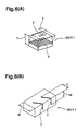
- the circumferential rigidity K of each tread element 6 is defined as the quotient of a tangential force F in kgf received at the ground contacting region divided by the displacement y in mm in the ground contacting region.
- K F y
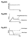
- the present inventor studied relationships between frictional coefficient and various factors, and discovered that it is most important that the tyre displays a maximum frictional coefficient under the above-mentioned relatively small slip rate of from 5 % to 10 %. As explained above, because a certain difference in slip rate is provided between the front and rear wheels, when the maximum frictional coefficient of the rear tyres is less than the maximum frictional coefficient of the front tyres, a larger braking force can be obtained.
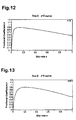
- Fig.10 shows an exemplary ⁇ -s curve, wherein " ⁇ " on the vertical axis is the frictional coefficient between the tyre tread and road surface, and "s" on the horizontal axis is the slip rate therebetween.
- the maximum frictional coefficient occurs at a slip rate of about 7 %. In general, however, the maximum frictional coefficient occurs at a relatively higher slip rate.
- this inclination is called " ⁇ -s stiffness".
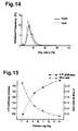
- Fig.15 shows an exemplary relationship between the pattern rigidity (index) and the slip rate, and an exemplary relationship between the pattern rigidity (index) and the ⁇ -s stiffness (index). As shown in this figure, as the pattern rigidity increases, the ⁇ -s stiffness increases, and the slip rate at the maximum frictional coefficient decreases.
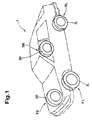
- a vehicle 1 according to the present invention is an automobile (passenger car) and has an Anti Lock Brake System (ABS).
- ABS is adjusted such that, when the ABS is in operation, the slip rate is about 5 % to about 10 % and the slip rate is lower on the rear wheels RR and RL than the front wheels FR and FL as shown in Fig.14.
- pneumatic tyres 2R and 2L are mounted, and on the rear wheels RR and RL, pneumatic tyres 3R and 3L are mounted.
- each of the pneumatic tyres 2L, 2R, 3L and 3R comprises a tread portion 4 provided with a plurality of tread elements 6 divided by tread grooves 5.
- the tread groove 5 is a groove having a certain width enough for water drainage.
- the tread grooves 5 may be circumferential grooves 5a and axial grooves 5b.
- various grooves e.g. straight grooves, curved grooves or zigzag grooves may be used.
- the tread elements 6 may include a circumferentially continuous rib such as 6a shown in Fig.2 and/or circumferentially discontinuous blocks such as 6b shown in Figs.3 to 5.
- the tread pattern in this invention includes so called “rib pattern”, “block pattern”, “rib-and-block pattern”, “rib-and-lug pattern”, “lug pattern” and the like.
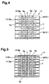
- the tread patterns can be symmetrical about the tyre equator C as shown in Figs.2 to 5, but it is also possible to make the tread patterns not symmetrical. Further, it is also possible to make the tread pattern bi-directional or unidirectional. Furthermore, as shown in Figs.4 and 5, it is possible that the tread elements 6s are provided with sipes 7 having no substantial width (for example under 1.0 mm).
- Fig.2 shows an example of the tread pattern comprising four straight circumferential grooves 5a.
- Fig.3 shows an example of the tread pattern comprising four straight circumferential grooves 5a and axial grooves 5b extending straight from one tread edge to the other tread edge in parallel with the tyre axial direction.
- Fig.4 shows an example of the tread pattern which is similar to Fig.3, but with sipes 7 extending straight from one tread edge to the other tread edge in parallel with the tyre axial direction which are disposed alternately with the axial grooves 5b.
- Fig.5 shows an example of the tread pattern which is similar to Fig.4, but the number of sipes 7 is doubled.
- all the tread elements 6 are a circumferentially continuous rib.
- the pattern is a rib pattern.
- all the tread elements 6 are a rectangular block.
- the patterns are block patters.
- the difference between the pattern in Fig.2 and that in Fig.3 is the number of axial grooves 5b.
- the difference between the patterns in Figs.3-5 is the number of sipes 7.
- the tread pattern rigidity Pr of each rear tyre 3L and 3R is set to be more than the tread pattern rigidity Pf of each front tyre 2L and 2R.
- the tread pattern rigidity Pr is more than 1.1 times, more preferably more than 1.25 times, still more preferably more 1.50 times the pattern rigidity Pf.
- the pattern rigidity P (Pf, Pr) is set in the range of from 70 to 200 kgf/mm cm 2 to achieve both steering stability and wet performance.
- the tread pattern rigidity P (Pr, Pf) is defined as the quotient of the total of circumferential rigidity of all the tread elements 6 existing partially or wholly in the ground contacting region around the tyre which is divided by the area in cm 2 of this ground contacting region.
- the ground contacting region is defined as the region between the tread edges E.
- the tread edges E are the axially outmost edges (e) of the ground contacting area 9 of the tread portion 4 when the tyre is under its standard loaded condition mounted on a standard rim and inflated to a standard inner pressure and loaded with a standard load.
- the standard rim is the "standard rim” specified in JATMA, the “Measuring Rim” in ETRTO, the “Design Rim” in TRA or the like.
- the standard pressure is the “maximum air pressure” in JATMA, the “Inflation Pressure” in ETRTO, the maximum pressure given in the "Tyre Load Limits at Various Cold Inflation Pressures” table in TRA or the like.
- the standard load is the "maximum load capacity" in JATMA, the “Load Capacity” in ETRTO, the maximum value given in the above-mentioned table in TRA or the like.
- the circumferential rigidity K is calculated on the assumption that the tread element 6 is a block having a height equal to 50% of the actual height (h) and a circumferential length equal to that of a portion of the rib actually contacting with the ground under the standard loaded condition.
- the width W2 to the tread edge E is used instead of the actual block width W3.
- the rigidity may be obtained by applying a quadrature and/or co-ordinate conversion.
- the front tyres 2 have a ⁇ -s stiffness af
- the rear tyres 3 have a ⁇ -s stiffness ⁇ r which is larger than the ⁇ -s stiffness ⁇ f.
- the ⁇ -s stiffness ⁇ ( ⁇ r, ⁇ f) is, as explained above, the inclination angle of the substantially straight portion of the ⁇ -s curve of the tyre which rises from the origin of rectangular co-ordinates, wherein the horizontal axis is the slip rate (s) and the vertical axis is the frictional coefficient ⁇ .
- the rear tyre's ⁇ -s stiffness ⁇ r is preferably more than 1.1 times, more preferably more than 1.15 times, still more preferably more than 1.30 times the front tyre's ⁇ -s stiffness ⁇ f.
- the slip rate (s) between the tyre and road is wherein
- the ⁇ -s curve is obtained by plotting data of the slip rate (s) and frictional coefficient ⁇ computed as above.
- the number of sipes per one block is preferably one to three.
- the total axial edge length Sf of the front tyre 2 is set to be more than the total axial edge length Sr of the rear tyre 3.
- the total axial edge length S (Sf, Sr) is the total length in mm of the axial component of groove edges existing in the ground contacting region under the above-mentioned standard loaded condition.
- the groove edges include edges of the sipes 7 as well as edges of the tread grooves 5 such as circumferential grooves 5a and axial grooves 5b and the like.
- a tread groove 5 having a certain width two edges one on each side thereof are counted.
- two edges should be regard as one edge.
- the total axial edge length Sf of the front tyre is more than 1.5 times, more preferably more than 1.8 times, still more preferably more than 2.0 times the total axial edge length Sr of the rear tyre.
- Table 1 shows the results of a comparison test conducted using two types of 1500cc FF-type Japanese passenger cars (A and B) both equipped with ABS.
- the test car was run on a wet asphalt road and sharply braked at a speed of 100 km/hr so that the ABS worked. Such sharp braking was repeated five times to obtain the average braking distance.
- the specifications of the test tyres A, B, C and D used are shown in Table 2.
- the pitch number corresponds to the number of axial grooves.
Landscapes
- Engineering & Computer Science (AREA)
- Mechanical Engineering (AREA)
- Tires In General (AREA)
- Regulating Braking Force (AREA)
Applications Claiming Priority (2)
| Application Number | Priority Date | Filing Date | Title |
|---|---|---|---|
| JP33151898 | 1998-11-20 | ||
| JP10331518A JP3064271B2 (ja) | 1998-11-20 | 1998-11-20 | 自動車およびそれに用いる前輪用と後輪用の空気入りタイヤの組み合わせ |
Publications (3)
| Publication Number | Publication Date |
|---|---|
| EP1002666A2 true EP1002666A2 (de) | 2000-05-24 |
| EP1002666A3 EP1002666A3 (de) | 2002-03-13 |
| EP1002666B1 EP1002666B1 (de) | 2005-10-12 |
Family
ID=18244553
Family Applications (1)
| Application Number | Title | Priority Date | Filing Date |
|---|---|---|---|
| EP99309259A Expired - Lifetime EP1002666B1 (de) | 1998-11-20 | 1999-11-19 | Vorder-und-hinter-Reifenkombination für Fahrzeug mit ABS und Fahrzeug |
Country Status (4)
| Country | Link |
|---|---|
| US (1) | US6715522B1 (de) |
| EP (1) | EP1002666B1 (de) |
| JP (1) | JP3064271B2 (de) |
| DE (1) | DE69927657T2 (de) |
Cited By (3)
| Publication number | Priority date | Publication date | Assignee | Title |
|---|---|---|---|---|
| US7360569B2 (en) * | 2003-12-09 | 2008-04-22 | Sumitomo Rubber Industries, Ltd. | Pneumatic tire with tread including circumferential rib region, block regions and sipes |
| FR2947234A1 (fr) * | 2009-06-30 | 2010-12-31 | Michelin Soc Tech | Ensemble routier comprenant un vehicule et un train de pneus. |
| EP3031624A1 (de) * | 2014-12-12 | 2016-06-15 | Sumitomo Rubber Industries Limited | Luftreifen |
Families Citing this family (21)
| Publication number | Priority date | Publication date | Assignee | Title |
|---|---|---|---|---|
| JP2001097005A (ja) * | 1999-09-29 | 2001-04-10 | Toyo Tire & Rubber Co Ltd | Abs装着車用空気入りタイヤ |
| JP4634626B2 (ja) * | 2001-02-23 | 2011-02-16 | 株式会社ブリヂストン | 前後輪用空気入りタイヤユニット、前後輪用空気入りタイヤユニットの装着方法及び前後輪用空気入りタイヤユニットを装着した車両 |
| JP2010018154A (ja) * | 2008-07-10 | 2010-01-28 | Bridgestone Corp | タイヤ |
| JP5359322B2 (ja) * | 2009-01-30 | 2013-12-04 | 横浜ゴム株式会社 | 空気入りタイヤユニット |
| WO2010137273A1 (ja) * | 2009-05-25 | 2010-12-02 | 株式会社ブリヂストン | 空気入りタイヤ |
| RU2521899C1 (ru) * | 2010-10-29 | 2014-07-10 | Мишлен Решерш Э Текник С.А. | Протектор шины, содержащий несколько слоев износа |
| BR112015014264A2 (pt) | 2012-12-19 | 2017-07-11 | Bridgestone Americas Tire Operations Llc | pneu com desempenho bidirecional |
| USD741790S1 (en) | 2013-01-09 | 2015-10-27 | Bridgestone Americas Tire Operations, Llc | Tire tread |
| US9889710B2 (en) | 2013-07-24 | 2018-02-13 | The Yokohama Rubber Co., Ltd. | Pneumatic tire mount method, and combination pneumatic tire |
| USD730817S1 (en) | 2013-10-09 | 2015-06-02 | Bridgestone Americas Tire Operations, Llc | Tire tread |
| USD734247S1 (en) | 2013-10-09 | 2015-07-14 | Bridgestone Americas Tire Operations, Llc | Tire tread |
| USD740216S1 (en) | 2013-10-09 | 2015-10-06 | Bridgestone Americas Tire Operations, Llc | Tire tread portion |
| USD740209S1 (en) | 2014-03-03 | 2015-10-06 | Bridgestone Americas Tire Operations, Llc | Tire tread |
| USD740211S1 (en) | 2014-03-03 | 2015-10-06 | Bridgestone Americas Tire Operations, Llc | Tire tread |
| USD810007S1 (en) | 2016-03-03 | 2018-02-13 | Bridgestone Americas Tire Operations, Llc | Tire tread |
| USD830290S1 (en) | 2017-06-01 | 2018-10-09 | Bridgestone Americas Tire Operations, Llc | Tire |
| USD818943S1 (en) | 2017-06-01 | 2018-05-29 | Bridgestone Americas Tire Operations, Llc | Tire |
| US11167595B2 (en) * | 2017-11-10 | 2021-11-09 | Paccar Inc | Tire tread with reduced rolling resistance |
| JP7625835B2 (ja) * | 2020-11-24 | 2025-02-04 | 住友ゴム工業株式会社 | タイヤ |
| JP7832438B2 (ja) * | 2021-09-17 | 2026-03-18 | 横浜ゴム株式会社 | タイヤ |
| JP2024037597A (ja) * | 2022-09-07 | 2024-03-19 | 住友ゴム工業株式会社 | 空気入りタイヤ |
Family Cites Families (10)
| Publication number | Priority date | Publication date | Assignee | Title |
|---|---|---|---|---|
| JP2901244B2 (ja) * | 1988-01-22 | 1999-06-07 | 株式会社ブリヂストン | 自動車とタイヤの組合せ体 |
| JPH03135749A (ja) * | 1989-10-20 | 1991-06-10 | Sumitomo Rubber Ind Ltd | タイヤの合成した前後剛性の測定方法及びタイヤトレッド部の前後剛性の測定方法 |
| JP3023191B2 (ja) * | 1991-03-07 | 2000-03-21 | 株式会社ブリヂストン | カート用ラジアルタイヤの組合せ構造 |
| JP3035005B2 (ja) * | 1991-06-26 | 2000-04-17 | 株式会社ブリヂストン | 空気入りラジアルタイヤのタイヤ対 |
| JP3135749B2 (ja) | 1993-06-24 | 2001-02-19 | 株式会社 神崎高級工機製作所 | 車両走行用のhst式変速装置 |
| ES2150531T3 (es) | 1994-06-23 | 2000-12-01 | Bridgestone Corp | Cubiertas de neumatico. |
| EP0722851A1 (de) * | 1995-01-13 | 1996-07-24 | BRIDGESTONE/FIRESTONE, Inc. | Reifen mit verbesserter Wasserverdrängungsfähigkeit |
| JP3150893B2 (ja) * | 1996-01-12 | 2001-03-26 | 住友ゴム工業株式会社 | タイヤ識別方法および装置 |
| EP0913274B2 (de) | 1996-12-10 | 2007-03-28 | The Yokohama Rubber Co., Ltd. | Luftreifen und luftreifenset |
| JP3901830B2 (ja) | 1998-03-03 | 2007-04-04 | 株式会社ブリヂストン | 後輪駆動乗用車用空気入りラジアル・タイヤ |
-
1998
- 1998-11-20 JP JP10331518A patent/JP3064271B2/ja not_active Expired - Fee Related
-
1999
- 1999-11-18 US US09/442,267 patent/US6715522B1/en not_active Expired - Lifetime
- 1999-11-19 DE DE69927657T patent/DE69927657T2/de not_active Expired - Lifetime
- 1999-11-19 EP EP99309259A patent/EP1002666B1/de not_active Expired - Lifetime
Cited By (6)
| Publication number | Priority date | Publication date | Assignee | Title |
|---|---|---|---|---|
| US7360569B2 (en) * | 2003-12-09 | 2008-04-22 | Sumitomo Rubber Industries, Ltd. | Pneumatic tire with tread including circumferential rib region, block regions and sipes |
| CN100446998C (zh) * | 2003-12-09 | 2008-12-31 | 住友橡胶工业株式会社 | 充气轮胎 |
| FR2947234A1 (fr) * | 2009-06-30 | 2010-12-31 | Michelin Soc Tech | Ensemble routier comprenant un vehicule et un train de pneus. |
| WO2011000802A1 (fr) * | 2009-06-30 | 2011-01-06 | Societe De Technologie Michelin | Ensemble routier comprenant un vehicule et un train de pneus. |
| EP3031624A1 (de) * | 2014-12-12 | 2016-06-15 | Sumitomo Rubber Industries Limited | Luftreifen |
| US10232670B2 (en) | 2014-12-12 | 2019-03-19 | Sumitomo Rubber Industries, Ltd. | Pneumatic tire |
Also Published As
| Publication number | Publication date |
|---|---|
| EP1002666B1 (de) | 2005-10-12 |
| JP3064271B2 (ja) | 2000-07-12 |
| DE69927657D1 (de) | 2006-02-23 |
| DE69927657T2 (de) | 2006-06-08 |
| EP1002666A3 (de) | 2002-03-13 |
| US6715522B1 (en) | 2004-04-06 |
| JP2000158908A (ja) | 2000-06-13 |
Similar Documents
| Publication | Publication Date | Title |
|---|---|---|
| EP1002666B1 (de) | Vorder-und-hinter-Reifenkombination für Fahrzeug mit ABS und Fahrzeug | |
| EP0875403B1 (de) | Luftreifen | |
| EP1961586B1 (de) | Spikeloser Reifen | |
| US10752057B2 (en) | Pneumatic tire | |
| US6340040B1 (en) | Vehicle tire including main grooves and lug grooves | |
| EP0904960B1 (de) | Spikeloser luftreifen | |
| EP0688685B1 (de) | Luftreifen | |
| JP3519473B2 (ja) | 氷雪上走行用空気入りタイヤ | |
| EP3248810B1 (de) | Reifen | |
| US6102093A (en) | Pneumatic tire including long blocks and wide blocks | |
| CN104010836A (zh) | 乘用车用充气子午线轮胎及其使用方法 | |
| JPH082215A (ja) | 空気入りタイヤ | |
| JP7547863B2 (ja) | タイヤ | |
| EP0812708B1 (de) | Radiale Luftreifen | |
| JP4979864B2 (ja) | 自動車用高性能タイヤ | |
| EP0916523B1 (de) | Luftreifen | |
| JP4072803B2 (ja) | 空気入りスタッドレスタイヤ | |
| EP4079540B1 (de) | Reifen | |
| KR101197195B1 (ko) | 비대칭 트레드 프로파일을 갖는 공기 타이어 | |
| JPH09226326A (ja) | 空気入りタイヤ | |
| JPH11245621A (ja) | 後輪駆動乗用車用空気入りラジアル・タイヤ | |
| JP3878757B2 (ja) | 重荷重用空気入りタイヤ | |
| JP4657404B2 (ja) | 空気入りタイヤ | |
| JP4488457B2 (ja) | 乗用車用空気入りタイヤ | |
| JP3517366B2 (ja) | Absを具えた自動車用の空気入りタイヤ |
Legal Events
| Date | Code | Title | Description |
|---|---|---|---|
| PUAI | Public reference made under article 153(3) epc to a published international application that has entered the european phase |
Free format text: ORIGINAL CODE: 0009012 |
|
| AK | Designated contracting states |
Kind code of ref document: A2 Designated state(s): AT BE CH CY DE DK ES FI FR GB GR IE IT LI LU MC NL PT SE Kind code of ref document: A2 Designated state(s): DE FR GB |
|
| AX | Request for extension of the european patent |
Free format text: AL;LT;LV;MK;RO;SI |
|
| PUAL | Search report despatched |
Free format text: ORIGINAL CODE: 0009013 |
|
| AK | Designated contracting states |
Kind code of ref document: A3 Designated state(s): AT BE CH CY DE DK ES FI FR GB GR IE IT LI LU MC NL PT SE |
|
| AX | Request for extension of the european patent |
Free format text: AL;LT;LV;MK;RO;SI |
|
| 17P | Request for examination filed |
Effective date: 20020821 |
|
| AKX | Designation fees paid |
Free format text: DE FR GB |
|
| 17Q | First examination report despatched |
Effective date: 20030514 |
|
| GRAP | Despatch of communication of intention to grant a patent |
Free format text: ORIGINAL CODE: EPIDOSNIGR1 |
|
| GRAS | Grant fee paid |
Free format text: ORIGINAL CODE: EPIDOSNIGR3 |
|
| GRAA | (expected) grant |
Free format text: ORIGINAL CODE: 0009210 |
|
| AK | Designated contracting states |
Kind code of ref document: B1 Designated state(s): DE FR GB |
|
| REG | Reference to a national code |
Ref country code: GB Ref legal event code: FG4D |
|
| REF | Corresponds to: |
Ref document number: 69927657 Country of ref document: DE Date of ref document: 20060223 Kind code of ref document: P |
|
| ET | Fr: translation filed | ||
| PLBE | No opposition filed within time limit |
Free format text: ORIGINAL CODE: 0009261 |
|
| STAA | Information on the status of an ep patent application or granted ep patent |
Free format text: STATUS: NO OPPOSITION FILED WITHIN TIME LIMIT |
|
| 26N | No opposition filed |
Effective date: 20060713 |
|
| PGFP | Annual fee paid to national office [announced via postgrant information from national office to epo] |
Ref country code: GB Payment date: 20141119 Year of fee payment: 16 |
|
| REG | Reference to a national code |
Ref country code: FR Ref legal event code: PLFP Year of fee payment: 17 |
|
| PGFP | Annual fee paid to national office [announced via postgrant information from national office to epo] |
Ref country code: DE Payment date: 20151110 Year of fee payment: 17 |
|
| PGFP | Annual fee paid to national office [announced via postgrant information from national office to epo] |
Ref country code: FR Payment date: 20151008 Year of fee payment: 17 |
|
| GBPC | Gb: european patent ceased through non-payment of renewal fee |
Effective date: 20151119 |
|
| PG25 | Lapsed in a contracting state [announced via postgrant information from national office to epo] |
Ref country code: GB Free format text: LAPSE BECAUSE OF NON-PAYMENT OF DUE FEES Effective date: 20151119 |
|
| REG | Reference to a national code |
Ref country code: DE Ref legal event code: R119 Ref document number: 69927657 Country of ref document: DE |
|
| REG | Reference to a national code |
Ref country code: FR Ref legal event code: ST Effective date: 20170731 |
|
| PG25 | Lapsed in a contracting state [announced via postgrant information from national office to epo] |
Ref country code: FR Free format text: LAPSE BECAUSE OF NON-PAYMENT OF DUE FEES Effective date: 20161130 |
|
| PG25 | Lapsed in a contracting state [announced via postgrant information from national office to epo] |
Ref country code: DE Free format text: LAPSE BECAUSE OF NON-PAYMENT OF DUE FEES Effective date: 20170601 |