EP1001484B1 - Antennenvorrichtung und tragbares elektronisches Funkgerät mit einer solchen Antennenvorrichtung - Google Patents
Antennenvorrichtung und tragbares elektronisches Funkgerät mit einer solchen Antennenvorrichtung Download PDFInfo
- Publication number
- EP1001484B1 EP1001484B1 EP99122509A EP99122509A EP1001484B1 EP 1001484 B1 EP1001484 B1 EP 1001484B1 EP 99122509 A EP99122509 A EP 99122509A EP 99122509 A EP99122509 A EP 99122509A EP 1001484 B1 EP1001484 B1 EP 1001484B1
- Authority
- EP
- European Patent Office
- Prior art keywords
- feeding spring
- antenna device
- antenna
- ribs
- holder
- Prior art date
- Legal status (The legal status is an assumption and is not a legal conclusion. Google has not performed a legal analysis and makes no representation as to the accuracy of the status listed.)
- Expired - Lifetime
Links
Images


Classifications
-
- H—ELECTRICITY
- H01—ELECTRIC ELEMENTS
- H01Q—ANTENNAS, i.e. RADIO AERIALS
- H01Q1/00—Details of, or arrangements associated with, antennas
- H01Q1/12—Supports; Mounting means
- H01Q1/1207—Supports; Mounting means for fastening a rigid aerial element
- H01Q1/1214—Supports; Mounting means for fastening a rigid aerial element through a wall
-
- H—ELECTRICITY
- H01—ELECTRIC ELEMENTS
- H01Q—ANTENNAS, i.e. RADIO AERIALS
- H01Q1/00—Details of, or arrangements associated with, antennas
- H01Q1/12—Supports; Mounting means
- H01Q1/22—Supports; Mounting means by structural association with other equipment or articles
- H01Q1/24—Supports; Mounting means by structural association with other equipment or articles with receiving set
- H01Q1/241—Supports; Mounting means by structural association with other equipment or articles with receiving set used in mobile communications, e.g. GSM
- H01Q1/242—Supports; Mounting means by structural association with other equipment or articles with receiving set used in mobile communications, e.g. GSM specially adapted for hand-held use
-
- H—ELECTRICITY
- H04—ELECTRIC COMMUNICATION TECHNIQUE
- H04B—TRANSMISSION
- H04B1/00—Details of transmission systems, not covered by a single one of groups H04B3/00 - H04B13/00; Details of transmission systems not characterised by the medium used for transmission
- H04B1/38—Transceivers, i.e. devices in which transmitter and receiver form a structural unit and in which at least one part is used for functions of transmitting and receiving
- H04B1/3827—Portable transceivers
- H04B1/3833—Hand-held transceivers
Definitions
- the present invention relates to an antenna device in accordance with the generic clause of claim 1 to be assembled from the outside of an electronic appliance case of, for example, a radio appliance or a portable phone.
- an electronic appliance case of, for example, a radio appliance or a portable phone.
- it relates to a configuration comprising ribs in the case for preventing escape of a feeding spring.
- FIG. 6 Such a conventional configuration is shown in FIG. 6 which has been adopted for attaching the antenna onto the case in an antenna device to be assembled from the outside of an electronic appliance case of a radio appliance or a portable phone. That is, as shown in FIG. 6, an antenna 11 is fixed together with a holder 12 and a feeding spring 13 through an antenna inserting hole provided in a case 14 by screwing.
- an object of the invention is to provide an antenna device without the risk of displacement or escape of a feeding spring.
- the escape and the displacement of the feeding spring can be achieved.
- an inclination is formed at the tip portion of the ribs in the direction for mounting the feeding spring.
- a further aspect of the invention is the antenna device according to any of the first to third aspects, wherein a curvature is formed at the tip portion of the ribs along the antenna insertion direction, the effect of simplifying attachment of the holder and the feeding spring can be achieved.
- a further aspect of the invention is the antenna device according to the first aspect, wherein the ribs are provided parallel to the antenna insertion direction at least at one point of one side in the vicinity of the hole, the effect of preventing escape of the feeding spring can be achieved.
- a further aspect of the invention is the antenna device according to the second aspect, wherein the ribs are provided parallel to the antenna insertion direction at least at one point of one side in the vicinity of the hole, the effect of preventing escape of the feeding spring can be achieved.
- a further aspect of the invention is a portable radio electronic appliance comprising the antenna device according to any of the first to sixth aspects, the effect of preventing escape or rotation of the feeding spring in the portable radio electronic appliance can be achieved.
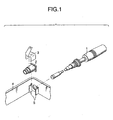
- FIG. 1 is an exploded perspective view showing the configuration of an antenna device according to an embodiment of the invention.
- FIG. 2 is a plan view of the vicinity of the hole of the case in the antenna device according to the embodiment of the invention, viewed from above.
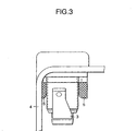
- FIG. 3 is a plan view showing the state with the holder and the feeding spring mounted in the antenna device according to the embodiment of the invention.
- FIG. 4 is an enlarged elevation view showing the configuration of the antenna device according to the embodiment of the invention immediately before completion of the assembly, viewed from the inside of the case.
- FIG. 5 is an enlarged elevation view showing the configuration of the antenna device according to the embodiment of the invention in the state after completion of the assembly, viewed from the inside of the case.
- FIG. 6 is an exploded perspective view showing the configuration of a conventional antenna device.
- FIG. 1 is an exploded perspective view showing the configuration of an antenna device according to the invention.
- the antenna device comprises an antenna 1 provided with a joining member for joining with a holder 2 through a hole, a case 4 comprising feeding spring escape/rotation prevention ribs 5 provided parallel to the antenna insertion direction in the vicinity of the hole, the holder 2 to be joined with the joining member inserted through the hole, and a feeding spring 3 engaged astride around the holder 2.
- FIG. 2 is a plan view of the vicinity of the hole of the case viewed from above. It is observed that the feeding spring escape/rotation prevention ribs 5 are provided parallel to the antenna insertion direction from the case 4. Moreover, it is observed that a curvature R is formed at the tip portion of the feeding spring escape/rotation prevention ribs 5 along the antenna insertion direction. The curvature R is formed for facilitating attachment of the parts.
- FIG. 3 is a plan view showing the state with the holder 2 and the feeding spring 3 mounted further to the state of FIG. 2. The positional relationship among the holder 2, the feeding spring 3 and the feeding spring escape/rotation prevention ribs 5 can be observed.
- FIG. 4 is an enlarged elevation view showing the configuration of the antenna device immediately before completion of the assembly, viewed from the inside of the case.
- FIG. 4 shows the state wherein the antenna is joined with the holder 2 already, and the feeding spring 3 is being attached onto the holder 2 by applying pressure. That is, it is understood that since the pressure is applied onto the feeding spring 3 for mounting on the holder 2, the feeding spring 3 can be mounted with the tip portion thereof placed around the holder 2 as well as the surface having the contact point astride on the surface of the holder 2 without contacting with the feeding spring escape/rotation prevention ribs 5. It is observed that an inclination is formed at the tip portion of the feeding spring escape/rotation prevention ribs 5 in the direction for mounting the feeding spring 3.
- FIG. 5 is an enlarged elevation view showing the configuration of the antenna device in the state after completion of the assembly, viewed from the inside of the case. Since assembly of the antenna device has been completed already in FIG. 5, for example, in the case a force of pulling out the feeding spring 3 is applied in the arrow direction, the feeding spring 3 is contacted with the feeding spring escape/rotation prevention ribs 5 owing to the spring force of the feeding spring 3 so that the feeding spring 3 cannot be pulled out owing to inhibition by the feeding spring escape/rotation prevention ribs 5.
- the feeding spring 3 is contacted with the feeding spring escape/rotation prevention ribs 5 owing to the spring force of the feeding spring 3 so that the feeding spring 3 cannot be rotated owing to inhibition by the feeding spring escape/rotation prevention ribs 5.
Landscapes
- Engineering & Computer Science (AREA)
- Computer Networks & Wireless Communication (AREA)
- Support Of Aerials (AREA)
- Mobile Radio Communication Systems (AREA)
- Telephone Set Structure (AREA)
Claims (6)
- Antennenvorrichtung, umfassend:eine Antenne (11) ausgestattet mit einem Verbindungsteil zum Verbinden mit einer Halterung (2; 12) durch eine Öffnung,ein Gehäuse (4; 14) mit einer Halterung (2; 12), die mit dem durch die Öffnung des Gehäuses (4; 14) eingeführten Verbindungsteil verbunden werden soll, und einer Zuführfeder (3; 13),
dadurch gekennzeichnet, dassdas Gehäuse (4) Zuführfederaustritt und Drehverhinderungsrippen (5) hat, die parallel zu der Antenneneinführrichtung in der Nähe der Öffnung bereit gestellt sind; unddie Zuführfeder (3) rittlings um die Halterung (2) eingreift, so dass in der montierten Vorrichtung die Zuführfeder in Berührung mit dem Zuführfederaustrittund Drehverhinderungsrippen (5) steht. - Antennenvorrichtung nach Anspruch 1, wobei an dem Spitzenteil der Rippen (5) in Einbaurichtung der Zuführfeder (3) eine Schräge ausgebildet ist.
- Antennenvorrichtung nach Anspruch 1, wobei an dem Spitzenteil der Rippen entlang der Antenneneinführrichtung eine Krümmung (R) ausgebildet ist.
- Antennenvorrichtung nach Anspruch 1, wobei die Rippen (5) zumindest an einer Stelle einer Seite in der Nähe der Öffnung parallel zu der Antenneneinführrichtung bereit gestellt sind.
- Antennenvorrichtung nach Anspruch 2, wobei die Rippen (5) zumindest an einer Stelle einer Seite in der Nähe der Öffnung parallel zu der Antenneneinführrichtung bereit gestellt sind.
- Tragbares elektronisches Funkgerät mit der Antennenvorrichtung nach Anspruch 1 bzw. 2.
Applications Claiming Priority (2)
| Application Number | Priority Date | Filing Date | Title |
|---|---|---|---|
| JP32214598A JP3645106B2 (ja) | 1998-11-12 | 1998-11-12 | アンテナ装置及び該アンテナ装置を備えた携帯無線電子機器 |
| JP32214598 | 1998-11-12 |
Publications (2)
| Publication Number | Publication Date |
|---|---|
| EP1001484A1 EP1001484A1 (de) | 2000-05-17 |
| EP1001484B1 true EP1001484B1 (de) | 2003-09-03 |
Family
ID=18140440
Family Applications (1)
| Application Number | Title | Priority Date | Filing Date |
|---|---|---|---|
| EP99122509A Expired - Lifetime EP1001484B1 (de) | 1998-11-12 | 1999-11-11 | Antennenvorrichtung und tragbares elektronisches Funkgerät mit einer solchen Antennenvorrichtung |
Country Status (5)
| Country | Link |
|---|---|
| US (1) | US6140971A (de) |
| EP (1) | EP1001484B1 (de) |
| JP (1) | JP3645106B2 (de) |
| CN (1) | CN1131574C (de) |
| DE (1) | DE69910946T2 (de) |
Families Citing this family (3)
| Publication number | Priority date | Publication date | Assignee | Title |
|---|---|---|---|---|
| JP2011061549A (ja) * | 2009-09-10 | 2011-03-24 | Panasonic Corp | 携帯端末 |
| US8531348B2 (en) | 2009-10-06 | 2013-09-10 | Ralink Technology Corp. | Electronic device with embedded antenna |
| CN203180042U (zh) * | 2013-01-31 | 2013-09-04 | 国基电子(上海)有限公司 | 电子装置 |
Family Cites Families (10)
| Publication number | Priority date | Publication date | Assignee | Title |
|---|---|---|---|---|
| US4190839A (en) * | 1977-12-13 | 1980-02-26 | American Antenna Corporation | Mobile antenna including quick-release mounting |
| DE3233976C1 (de) * | 1982-09-14 | 1983-08-25 | Daimler-Benz Ag, 7000 Stuttgart | Verdrehsicherung für Schrauben |
| IT206553Z2 (it) * | 1985-07-09 | 1987-08-10 | Zendar Spa | Supporto fisso per antenne |
| FR2631661B1 (fr) * | 1988-05-18 | 1990-09-14 | Mecaniplast | Dispositif pour fixer une embase d'antenne sur une paroi metallique recouverte d'une couche protectrice isolante, et rondelle dentee pour un tel dispositif |
| DE4126604A1 (de) * | 1991-08-12 | 1993-02-18 | Bosch Gmbh Robert | Anschlussklemme fuer einen elektrischen leiter |
| FR2694138B1 (fr) * | 1992-07-24 | 1994-08-19 | Alcatel Radiotelephone | Système d'adaptation entre une fiche d'antenne et un socle d'un radiotéléphone. |
| JP2536811B2 (ja) * | 1992-10-29 | 1996-09-25 | 株式会社タムラ電子 | アンテナ接続用コネクタ |
| JPH08139509A (ja) * | 1994-11-10 | 1996-05-31 | Kokusai Electric Co Ltd | アンテナの取付け構造 |
| FI955125A (fi) * | 1995-10-27 | 1997-04-28 | Nokia Mobile Phones Ltd | Antennin liitäntä |
| JPH10233608A (ja) * | 1997-02-19 | 1998-09-02 | Sony Corp | 携帯無線機およびアンテナ装置 |
-
1998
- 1998-11-12 JP JP32214598A patent/JP3645106B2/ja not_active Expired - Fee Related
-
1999
- 1999-11-10 US US09/437,933 patent/US6140971A/en not_active Expired - Lifetime
- 1999-11-11 DE DE69910946T patent/DE69910946T2/de not_active Expired - Lifetime
- 1999-11-11 CN CN99123534A patent/CN1131574C/zh not_active Expired - Fee Related
- 1999-11-11 EP EP99122509A patent/EP1001484B1/de not_active Expired - Lifetime
Also Published As
| Publication number | Publication date |
|---|---|
| US6140971A (en) | 2000-10-31 |
| EP1001484A1 (de) | 2000-05-17 |
| CN1254204A (zh) | 2000-05-24 |
| DE69910946D1 (de) | 2003-10-09 |
| CN1131574C (zh) | 2003-12-17 |
| JP3645106B2 (ja) | 2005-05-11 |
| JP2000151236A (ja) | 2000-05-30 |
| DE69910946T2 (de) | 2004-05-19 |
Similar Documents
| Publication | Publication Date | Title |
|---|---|---|
| EP1688306B1 (de) | Fahrzeugdachantenneninstallationsvorrichtung | |
| US20070165365A1 (en) | Structure of terminal protection cover of electronic apparatus and terminal protection cover attaching method | |
| US5114036A (en) | Covering plate for a preset hole on a computer housing | |
| US6256846B1 (en) | Fastening device | |
| EP1001484B1 (de) | Antennenvorrichtung und tragbares elektronisches Funkgerät mit einer solchen Antennenvorrichtung | |
| SK155697A3 (en) | Gripping device | |
| JP4283136B2 (ja) | 固定構造、プロテクタおよび電気接続箱 | |
| JP2002321628A (ja) | ステアリングシャフト保持クリップ | |
| US5945637A (en) | Terminal attachment structure having a cradle portion to prevent tottering of the terminal | |
| JP4242528B2 (ja) | アンテナ固定方法及び装置 | |
| JPH10199627A (ja) | アースジョイントコネクタの取付構造 | |
| JP4240687B2 (ja) | 移動体通信機のアンテナ取り付け部構造 | |
| JPH06283236A (ja) | フレキシブルフラットケーブルの端末部保護クリップ | |
| JP3043640B2 (ja) | 固定型アンテナ取付構造 | |
| JP3742961B2 (ja) | キャップの取り付け構造 | |
| KR100496968B1 (ko) | 이동통신 단말기의 안테나고정장치 | |
| EP0793300A3 (de) | Steckverbinder, Steckverbinderhalterung und Pannelanordnung für die Einbau elektronischer Bauteile | |
| US20050094995A1 (en) | Dial structure | |
| JP2008016333A (ja) | Hdmiコネクタ付き基板の取付方法及び取付構造 | |
| JP3734811B2 (ja) | アンテナ装置 | |
| JP2910477B2 (ja) | モジュラプラグ用ケーブル保護装置 | |
| JP4699798B2 (ja) | 配線ダクト | |
| JP3317210B2 (ja) | アースジョイントコネクタ | |
| JP2000287328A5 (de) | ||
| KR200149800Y1 (ko) | 트라이 포우드 하우징의 스파이더 조립체 빠짐 방지용 스토퍼 링 구조 |
Legal Events
| Date | Code | Title | Description |
|---|---|---|---|
| PUAI | Public reference made under article 153(3) epc to a published international application that has entered the european phase |
Free format text: ORIGINAL CODE: 0009012 |
|
| AK | Designated contracting states |
Kind code of ref document: A1 Designated state(s): DE FR GB SE |
|
| AX | Request for extension of the european patent |
Free format text: AL;LT;LV;MK;RO;SI |
|
| 17P | Request for examination filed |
Effective date: 20000621 |
|
| 17Q | First examination report despatched |
Effective date: 20000828 |
|
| AKX | Designation fees paid |
Free format text: DE FR GB SE |
|
| GRAH | Despatch of communication of intention to grant a patent |
Free format text: ORIGINAL CODE: EPIDOS IGRA |
|
| GRAS | Grant fee paid |
Free format text: ORIGINAL CODE: EPIDOSNIGR3 |
|
| GRAA | (expected) grant |
Free format text: ORIGINAL CODE: 0009210 |
|
| AK | Designated contracting states |
Kind code of ref document: B1 Designated state(s): DE FR GB SE |
|
| REG | Reference to a national code |
Ref country code: GB Ref legal event code: FG4D |
|
| REG | Reference to a national code |
Ref country code: SE Ref legal event code: TRGR |
|
| REF | Corresponds to: |
Ref document number: 69910946 Country of ref document: DE Date of ref document: 20031009 Kind code of ref document: P |
|
| ET | Fr: translation filed | ||
| PLBE | No opposition filed within time limit |
Free format text: ORIGINAL CODE: 0009261 |
|
| STAA | Information on the status of an ep patent application or granted ep patent |
Free format text: STATUS: NO OPPOSITION FILED WITHIN TIME LIMIT |
|
| 26N | No opposition filed |
Effective date: 20040604 |
|
| PGFP | Annual fee paid to national office [announced via postgrant information from national office to epo] |
Ref country code: FR Payment date: 20121130 Year of fee payment: 14 Ref country code: DE Payment date: 20121107 Year of fee payment: 14 |
|
| PGFP | Annual fee paid to national office [announced via postgrant information from national office to epo] |
Ref country code: GB Payment date: 20121107 Year of fee payment: 14 Ref country code: SE Payment date: 20121113 Year of fee payment: 14 |
|
| REG | Reference to a national code |
Ref country code: SE Ref legal event code: EUG |
|
| GBPC | Gb: european patent ceased through non-payment of renewal fee |
Effective date: 20131111 |
|
| REG | Reference to a national code |
Ref country code: FR Ref legal event code: ST Effective date: 20140731 |
|
| REG | Reference to a national code |
Ref country code: DE Ref legal event code: R119 Ref document number: 69910946 Country of ref document: DE Effective date: 20140603 |
|
| PG25 | Lapsed in a contracting state [announced via postgrant information from national office to epo] |
Ref country code: DE Free format text: LAPSE BECAUSE OF NON-PAYMENT OF DUE FEES Effective date: 20140603 Ref country code: SE Free format text: LAPSE BECAUSE OF NON-PAYMENT OF DUE FEES Effective date: 20131112 |
|
| PG25 | Lapsed in a contracting state [announced via postgrant information from national office to epo] |
Ref country code: GB Free format text: LAPSE BECAUSE OF NON-PAYMENT OF DUE FEES Effective date: 20131111 Ref country code: FR Free format text: LAPSE BECAUSE OF NON-PAYMENT OF DUE FEES Effective date: 20131202 |