EP1001402A2 - Système de présentation - Google Patents
Système de présentation Download PDFInfo
- Publication number
- EP1001402A2 EP1001402A2 EP99122206A EP99122206A EP1001402A2 EP 1001402 A2 EP1001402 A2 EP 1001402A2 EP 99122206 A EP99122206 A EP 99122206A EP 99122206 A EP99122206 A EP 99122206A EP 1001402 A2 EP1001402 A2 EP 1001402A2
- Authority
- EP
- European Patent Office
- Prior art keywords
- section
- posts
- presentation system
- presentation
- post
- Prior art date
- Legal status (The legal status is an assumption and is not a legal conclusion. Google has not performed a legal analysis and makes no representation as to the accuracy of the status listed.)
- Withdrawn
Links
- 230000000694 effects Effects 0.000 claims description 3
- 239000007787 solid Substances 0.000 claims 1
- 230000007704 transition Effects 0.000 claims 1
- 238000005192 partition Methods 0.000 description 7
- 239000000843 powder Substances 0.000 description 7
- 229910000831 Steel Inorganic materials 0.000 description 6
- 239000010959 steel Substances 0.000 description 6
- 238000009434 installation Methods 0.000 description 4
- 238000004519 manufacturing process Methods 0.000 description 4
- 238000010276 construction Methods 0.000 description 3
- 239000000123 paper Substances 0.000 description 3
- 238000004904 shortening Methods 0.000 description 3
- 229910000838 Al alloy Inorganic materials 0.000 description 2
- 238000004026 adhesive bonding Methods 0.000 description 2
- XAGFODPZIPBFFR-UHFFFAOYSA-N aluminium Chemical compound [Al] XAGFODPZIPBFFR-UHFFFAOYSA-N 0.000 description 2
- 229910052782 aluminium Inorganic materials 0.000 description 2
- 230000008901 benefit Effects 0.000 description 2
- 230000015572 biosynthetic process Effects 0.000 description 2
- 239000004744 fabric Substances 0.000 description 2
- 239000000463 material Substances 0.000 description 2
- 239000004952 Polyamide Substances 0.000 description 1
- 239000011111 cardboard Substances 0.000 description 1
- 239000000969 carrier Substances 0.000 description 1
- 230000008859 change Effects 0.000 description 1
- 239000002131 composite material Substances 0.000 description 1
- 230000008878 coupling Effects 0.000 description 1
- 238000010168 coupling process Methods 0.000 description 1
- 238000005859 coupling reaction Methods 0.000 description 1
- 239000010408 film Substances 0.000 description 1
- 230000003993 interaction Effects 0.000 description 1
- 239000004033 plastic Substances 0.000 description 1
- 239000002985 plastic film Substances 0.000 description 1
- 229920006255 plastic film Polymers 0.000 description 1
- 229920002647 polyamide Polymers 0.000 description 1
- 230000036316 preload Effects 0.000 description 1
- 239000012858 resilient material Substances 0.000 description 1
- 230000000284 resting effect Effects 0.000 description 1
- 238000009958 sewing Methods 0.000 description 1
- 125000006850 spacer group Chemical group 0.000 description 1
- 229920002994 synthetic fiber Polymers 0.000 description 1
- 230000007306 turnover Effects 0.000 description 1
Images


Classifications
-
- G—PHYSICS
- G09—EDUCATION; CRYPTOGRAPHY; DISPLAY; ADVERTISING; SEALS
- G09F—DISPLAYING; ADVERTISING; SIGNS; LABELS OR NAME-PLATES; SEALS
- G09F15/00—Boards, hoardings, pillars, or like structures for notices, placards, posters, or the like
- G09F15/0068—Modular articulated structures, e.g. stands, and articulation means therefor
-
- A—HUMAN NECESSITIES
- A47—FURNITURE; DOMESTIC ARTICLES OR APPLIANCES; COFFEE MILLS; SPICE MILLS; SUCTION CLEANERS IN GENERAL
- A47F—SPECIAL FURNITURE, FITTINGS, OR ACCESSORIES FOR SHOPS, STOREHOUSES, BARS, RESTAURANTS OR THE LIKE; PAYING COUNTERS
- A47F5/00—Show stands, hangers, or shelves characterised by their constructional features
- A47F5/10—Adjustable or foldable or dismountable display stands
- A47F5/13—Adjustable or foldable or dismountable display stands made of tubes or wire
-
- E—FIXED CONSTRUCTIONS
- E04—BUILDING
- E04B—GENERAL BUILDING CONSTRUCTIONS; WALLS, e.g. PARTITIONS; ROOFS; FLOORS; CEILINGS; INSULATION OR OTHER PROTECTION OF BUILDINGS
- E04B2/00—Walls, e.g. partitions, for buildings; Wall construction with regard to insulation; Connections specially adapted to walls
- E04B2/74—Removable non-load-bearing partitions; Partitions with a free upper edge
- E04B2/7407—Removable non-load-bearing partitions; Partitions with a free upper edge assembled using frames with infill panels or coverings only; made-up of panels and a support structure incorporating posts
- E04B2/7416—Removable non-load-bearing partitions; Partitions with a free upper edge assembled using frames with infill panels or coverings only; made-up of panels and a support structure incorporating posts with free upper edge, e.g. for use as office space dividers
- E04B2/7422—Removable non-load-bearing partitions; Partitions with a free upper edge assembled using frames with infill panels or coverings only; made-up of panels and a support structure incorporating posts with free upper edge, e.g. for use as office space dividers with separate framed panels without intermediary support posts
- E04B2/7427—Removable non-load-bearing partitions; Partitions with a free upper edge assembled using frames with infill panels or coverings only; made-up of panels and a support structure incorporating posts with free upper edge, e.g. for use as office space dividers with separate framed panels without intermediary support posts with adjustable angular connection of panels
- E04B2/7431—Removable non-load-bearing partitions; Partitions with a free upper edge assembled using frames with infill panels or coverings only; made-up of panels and a support structure incorporating posts with free upper edge, e.g. for use as office space dividers with separate framed panels without intermediary support posts with adjustable angular connection of panels using hinges having two parallel rotation axes
Definitions
- the present invention relates to a presentation system according to the preamble of claim 1.
- Such presentation systems also called displays, can be found primarily at exhibitions or trade fairs for presentation from graphic information in particular to primarily flexible information carriers such as paper, cardboard, plastic films, Fabric or fabric panels etc. in large quantities Use. They often serve as room dividers at the same time.
- the one on the floor in the The foot resting on the right angle to the lower bar is at the end connected to one end of a telescopic rod, which itself extends vertically from the foot upwards and also at right angles runs to the bottom bar.
- the other end of the telescopic pole has a mounting section for each outer elastically curved element.
- Each frame consists of two parallel, vertically extending side sections, a foot section connecting the side sections and one upper connecting section provided between the side sections, the parallel to the foot section or below is arranged at an angle to the side sections.
- the frame frames are at the top and bottom using spacer elements connected and pivotable relative to each other.
- DE 90 01 742 U1 also discloses a display panel arrangement with at least two frames, both on their sides have parallel legs, which are connected above and below by a cross member. On Leg of one frame is on one leg of the adjacent one Frame by means of two height-spaced swivel connections connected, each having a gear pair.
- This display panel arrangement is also in terms of size the individual frame little flexible. Beyond that is special the formation of the swivel connections is proportionate complex.
- a partition is also known from DE 30 26 305 A1, composed of support posts and partition elements is.
- the partition elements have a rigid partition plate that is surrounded by a frame.
- the frame is made of four a U-profile having spar ends formed, their abutting Ends attached to each other by means of connecting pieces are. These connecting pieces are designed as elbows, whose legs protrude into the spar ends and with these are on the one hand tense and on the other hand jammed. Hooks are formed on the connecting pieces of the partition elements, by means of which the partition elements in on the support posts attached eyelets can be hung.
- the partition has one stable construction. However, it is suitable due to its weight and the given size of their elements as well as their relative complex assembly only conditionally for flexible use especially fairs. In terms of size and weight The same finally applies to those in DE 85 28 710 U1 disclosed wall, which consists of several by means of coupling elements there are detachably coupled wall elements.
- the invention is based on the prior art according to the EP 0 231 447 A1 is based on the object of a simple design To create a presentation system that is as flexible as possible is and can be easily and safely assembled and disassembled.
- the form-fitting prevents Fixing the ends of the tensioning elements to the posts Vertical post that the lower end of the presentation section due to e.g. Drafts oscillate back and forth and the presentation section may be damaged becomes.
- Great flexibility of the presentation system according to the invention does not follow solely from the fact that the presentation system due to the detachable connection between the posts and the cross members can be folded such that it has compact dimensions when dismantled and thus can be easily transported to different locations. Rather, the arrangement that can be moved along the posts permits of the tensioning element also meet the respective requirements corresponding extension or shortening of the presentation section, the moreover in the connected state the posts and cross members can be made, i.e. without that entire presentation system would have to be dismantled.
- each post consists of at least one tubular element with an annular cross section.
- the posts are not just attractive Exterior, but also have a low weight, which in the With regard to easy transportation of the presentation system is an advantage.
- the length of the posts and thus the level of the presentation system to the respective requirements can be easily changed accordingly, so that in particular in interaction with the sliding arrangement of the Clamping element gives a variety of design options.
- the claim 3 provides that the tensioning element on Presentation section attached, preferably massive Has basic body.
- the tensioning element on Presentation section attached preferably massive Has basic body.
- the Basic body can about the own weight of the Basic body depending on the material of the presentation section for a defined preload of the presentation section be taken care of in particular the danger counter the tearing of the presentation section.
- the base body of the clamping element each have a tubular segment with a circular segment Cross section attached, which the respective end of the clamping element forms what, among other things with regard to the production costs can be rated as cheap because standard parts, i.e. for example sections or segments of standardized pipes can be used that are readily available on the market.
- the inner diameter the pipe segments of the clamping element slightly larger than that Outside diameter of the tubular elements of the posts, with the central axes of the pipe segments parallel in a common plane run to each other, with the central axes facing each other Pipe elements essentially coincide and perpendicular to the central axis of the base body of the clamping element stand.
- the claim 7 provides that the pipe segments of the Clamping element on the inner circumference each with an elastic Lining, preferably a felt section, to effect the rubbing engagement with the posts. This is about it is not just a simple measure to the frictional engagement to effect. Rather, for example, felt sections advantageous on the pipe segments of the clamping element also provided retrospectively or in the event of repeated wear Easy assembly and disassembly of the presentation system be replaced.
- an elastic Lining preferably a felt section
- system connectors are provided to two adjacent posts To connect pairs of posts by friction, being at two system connectors one at the bottom of the adjacent one Posts and one placed at the top of the adjacent posts is.
- the provision of system connectors causes on a further increase in the flexibility of the presentation system because the width and arrangement of the presentation system by connecting independent, each from a pair of posts, a lower and an upper cross member as well a presentation section with an associated clamping element existing Units according to the respective requirements can be adjusted.
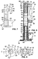
- Claim 9 provides that the tubular element with respect symmetrical about a plane perpendicular to its central axis is formed and each end has an internal thread section having. On the one hand, this has the advantage that the tubular element is easy to manufacture. On the other hand, there is one non-directional assembly of the tubular element possible, which is the structure of the presentation system.
- the contiguous Pipe elements of a post by means of a connecting element seamlessly connected the connecting element has an externally threaded portion which is in the adjacent Screwed internal thread sections of the corresponding pipe elements is. Due to the seamless connection of the pipe elements is a problem-free sliding along the tensioning element the entire length of the posts possible. Furthermore allows such a connecting element a simple and safe installation or extension according to requirements / Shortening the posts with little effort and especially without the need to use special Tools.
- connection element has a centering section, which connects to the external thread section and its Outside diameter is smaller than the outside diameter of the Male thread section, as specified in claim 11, assembly is further simplified because the connecting element not only angularly positioned with respect to the corresponding tubular element must be so that the external thread section of the Connecting element with the internal thread section of the tubular element can engage in screw engagement.
- the connecting element has one Internal thread section for fastening the foot element or of the system connector on the corresponding post.
- Claim 13 provides that the lower and the upper Cross element each have a hollow profile section whose ends each have a tubular section with an annular Cross section is fixed, the central axes of the pipe sections run parallel to each other in a common plane and perpendicular to the central axis of the hollow profile section stand.
- the cross elements thus have sufficient stability not just an advantageous light weight, but are also inexpensive and easy to manufacture because standard parts, i.e. standardized profiles or pipes are used that are easily available on the market. Furthermore is by the symmetrical design of the transverse elements is an undirected one Assembly possible (no left or right or upper or lower Side of the cross member) what the assembly of the presentation system simplified.
- Claims 14 and 15 give advantageous designs which, among other things the detachable frame-like connection of the Serve cross members with the posts. So is according to the claim 14 provided that the foot element or the system connector by means of a screw part with the respective pipe section of the corresponding cross element clamped non-positively is, the screw part with the internal thread portion the connecting element is in screw engagement, which in turn with its external thread section in the Internal thread section of the nearest pipe element of the corresponding post is screwed in and in the respective Pipe section of the corresponding cross member protrudes.
- the upper cross member at an upper, free corner of the presentation system with the nearest pipe element of the corresponding post using a plug connected to a shoulder portion rests on the respective pipe section of the upper cross element, engages tightly with one paragraph and with his End whose outer diameter is slightly smaller than that Inner diameter of the internally threaded section of the tubular element, is inserted into the nearest pipe element. So is it to connect the upper cross member to an outer one Post only necessary, a simple plug in the pipe section of the upper cross member and the corresponding Insert pipe element, no tools is needed.
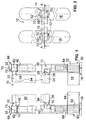
- the presentation system 10 has a pair of posts 12, a lower one Cross member 14 and an upper cross member 16, the pair Posts 12 are assigned two foot elements 18, each are connected to one of the posts 12, and one between the post 12 and the associated cross members 14, 16 extending, flexible presentation section 20 which with attached its upper end 22 to the upper cross member 16 is.
- the posts 12 and the transverse elements 14, 16 releasably like a frame connected with each other.
- a rod-shaped clamping element 26 is attached, whose ends 28 in the longitudinal direction of the posts 12 slidably disposed relative to the posts 12 and perpendicular to the posts 12 on the posts 12 are specified, which will be discussed in more detail below becomes.
- Each of the posts 12 has at least one tubular element 30 preferably aluminum or an aluminum alloy, which has an annular cross section.
- the tubular element 30 is shown in a plan view. That on has preferably deburred tubular element 30 deburred an anodized surface and is perpendicular to one its center axis 32 extending plane is symmetrical, so that it can be easily manufactured and an undirected Assembly is possible.
- the pipe element faces 30 one in relation to the total length of the tubular element 30 short internal thread section 34 (dashed in Fig. 12 shown), the connection of adjacent pipe elements 30 or the attachment of other parts.
- Exists Post 12 made of a plurality of tubular elements 30, i.e. at least two pipe elements 30, as shown in FIGS.
- connection element 36 which in Fig. 13 in A plan view is shown and preferably made of a plastic like polyamide, seamlessly connected.
- the connecting element 36 has an externally threaded section 38 which, 10 and 11 illustrate, in the neighboring Internally threaded sections 34 of the corresponding tubular elements 30 is screwed in. Closes on the external thread section 38 a cylindrical centering section 40 whose outer diameter is smaller than the outside diameter of the outside thread section 38.
- the connecting element 36 another one over the entire length of the connecting element 36 extending internal thread section 42 (dashed in Fig.
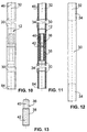
- FIG. 17 is a plan view Variant 36 'of the connecting element 36 with an external thread section 38 ', centering section 40' and internal thread section 42 '(shown in dashed lines) shows that primarily at the top End 46 such post 12 is used with a further posts 12 connected by the system connector 44 ' are (see in particular Fig.
- the lower cross member 14 is in one Front view or a plan view shown. That is preferable made of steel and powder-coated on its outer surface lower cross member 14 has a hollow profile section 48 with a rectangular outer cross-section, corresponding to it recessed ends 50 each have a tube section 52 fixed flush with an annular cross section, for example is soldered or welded, with the central axes 54 of the pipe sections 52 parallel in a common plane run to each other and perpendicular to the central axis 56 of the Stand hollow section 48, so that the lower cross member 14 with respect to the central axis 56 of the hollow profile section 48 vertical plane is symmetrical.
- the inner diameter of the pipe sections 52 is slightly larger than the outer diameter of the male threaded portion 38 of the Connecting element 36.
- the central axes 64 which is preferably on the hollow profile section 58 welded or soldered pipe sections 62 run in a common plane parallel to each other and are perpendicular to the central axis 66 of the hollow profile section 58, so that the upper cross member 16 with respect to the central axis 66 of the hollow section 58 vertical plane symmetrical is.
- the inside diameter of the pipe sections 62 is slightly larger than the external diameter of the external thread section 38 'of the connecting element 36'.
- FIGS. 1 to 3 the upper cross member 16 at an upper, free corner 68 of the presentation system 10, i.e. 1 to 3 on both sides, with the nearest pipe element 30 of the corresponding post 12 is connected by means of a plug 70 which in FIG. 16 is shown in more detail in a top view.
- a plug 70 which in FIG. 16 is shown in more detail in a top view.
- the preferred made of aluminum or an aluminum alloy, one Plug 70 having a powder-coated surface has a cylindrical shoulder portion 72 to which a cylindrical Paragraph 74 of smaller diameter, which in turn over a 45 ° bevel into a chamfered, cylindrical At the end of 76 even smaller diameter passes into the starting from its front, also for weight reasons Blind bore 78 (shown in dashed lines in Fig. 16) introduced can be.
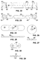
- the lower cross element 14 in the area of a lower, free corner 82 of the presentation system 10, i.e. 1 and 3 on both sides, on the respective lower ends 84 of the corresponding posts 12 below Using the foot element 18 attached. That has in 24 and 25 in a plan view and a front view shown, preferably made of sheet steel and a foot element 18 having a powder-coated surface in the middle an obliquely countersunk through hole 86 (in FIG. 25 shown in dashed lines) for receiving a screw part 88 (for example a countersunk screw), which one accordingly beveled head 90, preferably with a hexagon socket and an adjoining external thread section 92 for screw engagement with the internal thread section 42 of the connecting element 36.
- a screw part 88 for example a countersunk screw
- screw part 88 By means of the screw part 88 is the elongated one with rounded ends Foot element 18 with the respective tube section 52 of the lower one Cross member 14 clamped non-positively, which is Screw part 88 with the internal thread section 42 of the connecting element 36 is in screw engagement, which in turn with its external thread section 38 into the internal thread section 34 of the closest tubular element 30 of the corresponding one Post 12 is screwed and in the respective Pipe section 52 of the lower cross member 14 protrudes.
- the one diametrically opposite the upper end 22 lower end 24 of the presentation section 20 accordingly designed as a loop into which the tensioning element 26 is inserted.
- 1 and 3 are seams 94 for training the loops are shown in dashed lines.
- the loops can, however, also by gluing the respective end 22, 24 of the presentation section 20 or by another connection be formed, which also after assembly of the above Framework can be done.
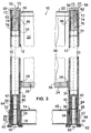
- the preferably made of steel and having a powder coated surface Clamping element 26 has one at the lower end 24 of the presentation section 20 attached as described above, preferably massive base body 96 with a round cross section.
- On the correspondingly recessed ends 98 of the base body 96 each have a tubular segment with a circular segment Cross-section and a segment angle less than 180 °, which is slightly on each side in the direction of its central axis 100 protrudes over the base body 96 and the respective Forms end 28 of the clamping element 26.
- the clamping element 26 is thus related one perpendicular to the central axis 102 of the base body 96 Level symmetrical.
- the inside diameter of the pipe segments 28 of the clamping element 26 is slightly larger than the outer diameter of the tubular elements 30 of the posts 12, wherein in the assembled state of the clamping element 26, the central axes 100 of the pipe segments 28 with the central axes 32 opposite one another Pipe elements 30 of the pair of posts 12 in essentially coincide, so that the clamping element 26 perpendicular fixed to the posts 12 in a form-fitting manner on the posts 12, arranged in the direction of the posts 12 but slidably is. As a result, the presentation section becomes 20th by the weight of the tensioning element guided on the post 12 26 excited.
- the clamping element 26 in the longitudinal direction the post 12 with the post 12 additionally in frictional engagement stand so that the clamping element 26 only with application a predetermined force relative to the post 12 is.
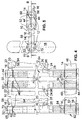
- 4 to 6 is a second embodiment of the Presentation system 10 shown in the assembled state, with reference to in particular FIGS. 1 to 3 described first embodiment corresponding parts are provided with the same reference numerals and in the following not be described again.
- the second embodiment differs from the first embodiment in that several pairs of posts 12 are associated with each Cross elements 14, 16, presentation section 20 and clamping element 26 to enlarge the presentation area with each other are connected.
- 4 to 6 are for clarity only one end of the presentation system 10 for the sake of it and the first connection of two pairs of posts 12 is shown; further pairs of posts 12 can be connected accordingly become.
- FIG Embodiment two system connectors 44, 44 ' is provided, one of which 44 at the lower end 84 of the adjacent Posts 12 and a 44 'at the top 46 of the adjacent one Post 12 is arranged.
- 28 and 29 as well 18 and 19 show the system connectors 44, 44 'in a top view or a front view.
- connection of the system connector 44, 44 'to the corresponding posts 12 is carried out analogously to that above described connection of the foot elements 18, i.e. under a Screw engagement through the through holes 104, 104 'extending screw parts 88 with in the nearest pipe elements 30 screwed connecting elements 36, 36 ', the pipe sections 52, 62 of the corresponding Cross elements 14, 16 on their end faces between the respective system connector 44, 44 'and the respective Pipe element 30 clamped.
- This allows adjacent posts 12 reliably connected to each other in an exactly parallel alignment be, it is also possible to neighboring lower cross elements 14 or upper cross elements 16 in a predetermined Fix the angular position to each other. It should be noted in this connection still that the lower system connector 44 like the foot elements 18 on the base of the presentation system 10 or lie on the floor.
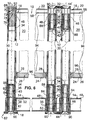
- FIG. 7 to 9 is a third embodiment of the Presentation system 10 shown in the assembled state, with reference to in particular FIGS. 1 to 6 corresponding embodiments with corresponding parts are provided with the same reference symbols and not subsequently be described again.
- the third embodiment differs from the second embodiment in that that at the free, lower corners 82 of the presentation system 10 another foot element 18 'is provided, which in the 26 and 27 in a plan view and a front view is shown. That preferably from a steel sheet has powder-coated surface existing foot element 18 ' a circular shape in plan view and is corresponding the foot element 18 in the center with a through hole 86 '(in Fig. 27 shown in dashed lines) for receiving the screw part 88 provided.
- the attachment of the foot element 18 'on outer post 12 is carried out analogously to the attachment described above of the foot element 18 and therefore will not be repeated explained.
- This foot element that offers less torque support 18 ' is used in particular when several Pairs of posts 12, each with associated cross members 14, 16, presentation section 20 and clamping element 26 with each other be connected and the stability of the presentation system 10 is achieved by the adjacent transverse elements 14, 16 of at least two pairs of posts 12 in include an angle of significantly less than 180 ° from the top view.
- FIGS. 30 to 35 show a basic illustration finally arrangement or structure variants of the presentation system 10, each of which is at least one of a Pair of posts 12, a lower cross member 14, an upper Cross member 16, a presentation section 20 and one Has clamping element 26 existing unit E.
- the size of the presentation area additionally by lengthening / shortening the presentation sections 20 (change the height of the posts 12 by adding / removing of tubular elements 30 or slidable connection of the Clamping elements 26 on the posts 12) the respective requirements can be easily adjusted accordingly.
- a presentation system with at least one pair of posts, a lower and an upper cross member that the pair Posts are assigned at least one foot element that with one of the posts is connected, and one is between the Post and the associated cross members extending, flexible Presentation section reveals that with its upper End is attached to the upper cross member.
- the posts and the cross members frame-like detachable with each other connected, being at the bottom of the presentation section a rod-shaped clamping element is attached, the Ends in the longitudinal direction of the posts relative to the Posts slidably arranged and perpendicular to the posts are positively attached to the posts.
Landscapes
- Engineering & Computer Science (AREA)
- Physics & Mathematics (AREA)
- Architecture (AREA)
- General Physics & Mathematics (AREA)
- Civil Engineering (AREA)
- Structural Engineering (AREA)
- Electromagnetism (AREA)
- Theoretical Computer Science (AREA)
- Liquid Crystal Substances (AREA)
- Separation By Low-Temperature Treatments (AREA)
- Eye Examination Apparatus (AREA)
- Invalid Beds And Related Equipment (AREA)
- Road Signs Or Road Markings (AREA)
- Mutual Connection Of Rods And Tubes (AREA)
Applications Claiming Priority (2)
| Application Number | Priority Date | Filing Date | Title |
|---|---|---|---|
| DE29820223U DE29820223U1 (de) | 1998-11-12 | 1998-11-12 | Präsentationssystem |
| DE29820223U | 1998-11-12 |
Publications (2)
| Publication Number | Publication Date |
|---|---|
| EP1001402A2 true EP1001402A2 (fr) | 2000-05-17 |
| EP1001402A3 EP1001402A3 (fr) | 2000-11-29 |
Family
ID=8065234
Family Applications (1)
| Application Number | Title | Priority Date | Filing Date |
|---|---|---|---|
| EP99122206A Withdrawn EP1001402A3 (fr) | 1998-11-12 | 1999-11-06 | Système de présentation |
Country Status (2)
| Country | Link |
|---|---|
| EP (1) | EP1001402A3 (fr) |
| DE (1) | DE29820223U1 (fr) |
Cited By (3)
| Publication number | Priority date | Publication date | Assignee | Title |
|---|---|---|---|---|
| WO2001091091A1 (fr) * | 2000-05-18 | 2001-11-29 | Bieri Blachen Ag | Dispositif pour tendre un materiau de type feuille et porte-affiches conçu avec ce dispositif |
| FR2821254A1 (fr) * | 2001-02-26 | 2002-08-30 | Alain Collard | Dispositif modulaire, a assemblage rapide, de construction de decors legers, permettant la presentation de visuels |
| DE102005054154A1 (de) * | 2005-11-09 | 2007-05-24 | Bernd Apel | Aufsteller |
Families Citing this family (17)
| Publication number | Priority date | Publication date | Assignee | Title |
|---|---|---|---|---|
| FR2793268B1 (fr) * | 1999-05-07 | 2001-07-13 | Reyem Sarl | Cloison de separation notamment de bureaux |
| DE10304943B3 (de) | 2003-02-06 | 2004-08-19 | Autoliv Development Ab | Endbeschlagstraffer |
| US9254051B2 (en) | 2013-01-11 | 2016-02-09 | Atomic Design, Inc. | Display system |
| WO2015058050A1 (fr) * | 2013-10-17 | 2015-04-23 | Atomic Design | Connecteur d'affichage |
| US9506636B2 (en) | 2014-05-20 | 2016-11-29 | Atomic Design Inc. | Lighted display connector |
| USD801433S1 (en) | 2015-06-18 | 2017-10-31 | Atomic Design Inc. | Base panel connector |
| USD802054S1 (en) | 2015-06-18 | 2017-11-07 | Atomic Design Inc. | Support connector |
| USD800840S1 (en) | 2015-06-19 | 2017-10-24 | Atomic Design Inc. | Panel connector |
| USD800839S1 (en) | 2015-06-19 | 2017-10-24 | Atomic Design Inc. | Base panel connector |
| USD800838S1 (en) | 2015-06-19 | 2017-10-24 | Atomic Design Inc. | Base panel connector |
| US9788668B2 (en) | 2015-06-19 | 2017-10-17 | Atomic Design Inc. | Display system |
| USD797857S1 (en) | 2015-06-19 | 2017-09-19 | Atomic Design Inc. | Panel connector |
| USD815689S1 (en) | 2015-10-14 | 2018-04-17 | Atomic Design Inc. | Display panel assembly |
| US10226715B2 (en) | 2015-10-14 | 2019-03-12 | Atomic Design Inc. | Display panel system |
| US10431130B2 (en) | 2015-12-10 | 2019-10-01 | Atomic Design Inc. | Display system |
| US10327545B2 (en) | 2016-08-26 | 2019-06-25 | Atomic Design Inc. | Display support system |
| US10473260B2 (en) | 2016-08-26 | 2019-11-12 | Atomic Design Inc. | Display support system |
Citations (11)
| Publication number | Priority date | Publication date | Assignee | Title |
|---|---|---|---|---|
| DE3026305A1 (de) | 1980-07-11 | 1982-02-04 | Eduard Rosenkranz u. Cie., 6290 Weilburg | Rahmen |
| DE3120656C1 (de) | 1981-05-23 | 1982-12-16 | Messerschmitt-Bölkow-Blohm GmbH, 8000 München | Spannrahmen |
| DE8528710U1 (de) | 1985-10-09 | 1986-01-30 | Fugmann, Stephan | Wand, die aus mehreren lösbar miteinander gekuppelten Wandelementen besteht |
| FR2587606A2 (fr) | 1985-04-03 | 1987-03-27 | Cre Rossi | Ensemble d'elements complementaires pour la realisation de cloisons de separation, de panneaux d'exposition et similaires |
| EP0231447A1 (fr) | 1985-11-12 | 1987-08-12 | Nimlok Company | Encart publicitaire portatif |
| DE8815358U1 (de) | 1988-12-10 | 1989-01-26 | Mez Ag, 7800 Freiburg | Regal, insbesondere Wand- oder Mittelraumregal |
| DE8907326U1 (de) | 1989-06-15 | 1989-08-10 | D-TEC Industriedesign GmbH, 4000 Düsseldorf | Vorrichtung zur Präsentation von Gardinen, Stores, Vertikaljalousetten, Rollos o.dgl. |
| DE9001742U1 (de) | 1989-02-14 | 1990-04-19 | Dimension & Design mpd Ltd., Basildon, Essex | Displaytafel-Anordnung |
| DE3801772C2 (fr) | 1988-01-22 | 1991-08-08 | Duscholux Gmbh, 6905 Schriesheim, De | |
| DE9103993U1 (de) | 1991-04-03 | 1991-10-31 | Papst, Hans Dieter, Dipl.-Ing., 7742 St Georgen | Schutzgitter mit fester Umrahmung |
| US5791391A (en) | 1996-06-17 | 1998-08-11 | Carter; Wallace Thomas | Display system |
Family Cites Families (3)
| Publication number | Priority date | Publication date | Assignee | Title |
|---|---|---|---|---|
| US4368586A (en) * | 1980-07-03 | 1983-01-18 | Forzelias Tage N | Tensioning and attachment means for display stands and similar devices |
| US4866866A (en) * | 1987-11-09 | 1989-09-19 | Rotter Bernard J | Collapsible sign |
| WO1992002919A1 (fr) * | 1990-08-02 | 1992-02-20 | Locke, Christina, Joyce | Support d'exposition |
-
1998
- 1998-11-12 DE DE29820223U patent/DE29820223U1/de not_active Expired - Lifetime
-
1999
- 1999-11-06 EP EP99122206A patent/EP1001402A3/fr not_active Withdrawn
Patent Citations (11)
| Publication number | Priority date | Publication date | Assignee | Title |
|---|---|---|---|---|
| DE3026305A1 (de) | 1980-07-11 | 1982-02-04 | Eduard Rosenkranz u. Cie., 6290 Weilburg | Rahmen |
| DE3120656C1 (de) | 1981-05-23 | 1982-12-16 | Messerschmitt-Bölkow-Blohm GmbH, 8000 München | Spannrahmen |
| FR2587606A2 (fr) | 1985-04-03 | 1987-03-27 | Cre Rossi | Ensemble d'elements complementaires pour la realisation de cloisons de separation, de panneaux d'exposition et similaires |
| DE8528710U1 (de) | 1985-10-09 | 1986-01-30 | Fugmann, Stephan | Wand, die aus mehreren lösbar miteinander gekuppelten Wandelementen besteht |
| EP0231447A1 (fr) | 1985-11-12 | 1987-08-12 | Nimlok Company | Encart publicitaire portatif |
| DE3801772C2 (fr) | 1988-01-22 | 1991-08-08 | Duscholux Gmbh, 6905 Schriesheim, De | |
| DE8815358U1 (de) | 1988-12-10 | 1989-01-26 | Mez Ag, 7800 Freiburg | Regal, insbesondere Wand- oder Mittelraumregal |
| DE9001742U1 (de) | 1989-02-14 | 1990-04-19 | Dimension & Design mpd Ltd., Basildon, Essex | Displaytafel-Anordnung |
| DE8907326U1 (de) | 1989-06-15 | 1989-08-10 | D-TEC Industriedesign GmbH, 4000 Düsseldorf | Vorrichtung zur Präsentation von Gardinen, Stores, Vertikaljalousetten, Rollos o.dgl. |
| DE9103993U1 (de) | 1991-04-03 | 1991-10-31 | Papst, Hans Dieter, Dipl.-Ing., 7742 St Georgen | Schutzgitter mit fester Umrahmung |
| US5791391A (en) | 1996-06-17 | 1998-08-11 | Carter; Wallace Thomas | Display system |
Cited By (4)
| Publication number | Priority date | Publication date | Assignee | Title |
|---|---|---|---|---|
| WO2001091091A1 (fr) * | 2000-05-18 | 2001-11-29 | Bieri Blachen Ag | Dispositif pour tendre un materiau de type feuille et porte-affiches conçu avec ce dispositif |
| FR2821254A1 (fr) * | 2001-02-26 | 2002-08-30 | Alain Collard | Dispositif modulaire, a assemblage rapide, de construction de decors legers, permettant la presentation de visuels |
| DE102005054154A1 (de) * | 2005-11-09 | 2007-05-24 | Bernd Apel | Aufsteller |
| DE102005054154B4 (de) * | 2005-11-09 | 2009-04-30 | Bernd Apel | Aufsteller |
Also Published As
| Publication number | Publication date |
|---|---|
| DE29820223U1 (de) | 1999-02-18 |
| EP1001402A3 (fr) | 2000-11-29 |
Similar Documents
| Publication | Publication Date | Title |
|---|---|---|
| EP1001402A2 (fr) | Système de présentation | |
| DE19529897A1 (de) | Halteelement aus Kunststoff | |
| EP0297033A2 (fr) | Elément de fixation pour une barre | |
| EP0966585A1 (fr) | Petite cabine autonome | |
| WO2021148669A1 (fr) | Système de structure et rayonnage | |
| DE8906283U1 (de) | Verbindungsbeschlag für Stabelemente | |
| DE4126991A1 (de) | Stab mit einer verbindungsanordnung | |
| EP0629253A1 (fr) | Systeme de construction | |
| DE2912815C2 (fr) | ||
| DE29603402U1 (de) | Rahmenwerk mit Winkel- oder Eckverbindungen von Metallprofilen, insbesondere aus Leichtmetall | |
| DE3914420A1 (de) | Knoten fuer rohrkonstruktionen od. dgl. | |
| DE3805232C2 (fr) | ||
| DE2915276C3 (de) | Verbindung für Flächenkonstruktionselemente | |
| DE202017107484U1 (de) | Tragvorrichtung mit einem Tragarm zum Tragen eines Gegenstandes | |
| DE7617050U1 (de) | Zerlegbarer schrank | |
| DE9204208U1 (de) | Verbindungsknoten für Fachwerke | |
| DE4219852A1 (de) | Vorrichtung für ein schraubenlos zusammenfügbares Regalsystem | |
| AT519924B1 (de) | System zur Herstellung einer Gabione oder eines Zauns | |
| DE1905829A1 (de) | Halterung zur Befestigung an hohlen,rohrfoermigen Traegern mit einem Schlitz auf einer ihrer Aussenflaechen | |
| DE9101423U1 (de) | Bausatz | |
| CH679174A5 (en) | Bar connector for lattice work structure | |
| DE9301561U1 (de) | Absperrschranke | |
| DE20218098U1 (de) | Verbindung für eine Verstrebung aus Rohr und damit aufgebaute Konstruktion | |
| DE20202484U1 (de) | Wandungssystem | |
| DE10225955A1 (de) | Gitter, Zaun sowie Fenstergitter und Türgitter |
Legal Events
| Date | Code | Title | Description |
|---|---|---|---|
| PUAI | Public reference made under article 153(3) epc to a published international application that has entered the european phase |
Free format text: ORIGINAL CODE: 0009012 |
|
| AK | Designated contracting states |
Kind code of ref document: A2 Designated state(s): AT BE CH CY DE DK ES FI FR GB GR IE IT LI LU MC NL PT SE |
|
| AX | Request for extension of the european patent |
Free format text: AL;LT;LV;MK;RO;SI |
|
| PUAL | Search report despatched |
Free format text: ORIGINAL CODE: 0009013 |
|
| AK | Designated contracting states |
Kind code of ref document: A3 Designated state(s): AT BE CH CY DE DK ES FI FR GB GR IE IT LI LU MC NL PT SE |
|
| AX | Request for extension of the european patent |
Free format text: AL;LT;LV;MK;RO;SI |
|
| RIC1 | Information provided on ipc code assigned before grant |
Free format text: 7G 09F 15/00 A, 7A 47F 5/13 B, 7E 04B 2/74 B |
|
| STAA | Information on the status of an ep patent application or granted ep patent |
Free format text: STATUS: THE APPLICATION HAS BEEN WITHDRAWN |
|
| 18W | Application withdrawn |
Withdrawal date: 20010411 |