EP0998601B1 - Kettenwirkmaschine, insbesondere häkelgalonmaschine - Google Patents
Kettenwirkmaschine, insbesondere häkelgalonmaschine Download PDFInfo
- Publication number
- EP0998601B1 EP0998601B1 EP98929184A EP98929184A EP0998601B1 EP 0998601 B1 EP0998601 B1 EP 0998601B1 EP 98929184 A EP98929184 A EP 98929184A EP 98929184 A EP98929184 A EP 98929184A EP 0998601 B1 EP0998601 B1 EP 0998601B1
- Authority
- EP
- European Patent Office
- Prior art keywords
- weft
- warp
- knitting
- machine according
- knitting machine
- Prior art date
- Legal status (The legal status is an assumption and is not a legal conclusion. Google has not performed a legal analysis and makes no representation as to the accuracy of the status listed.)
- Expired - Lifetime
Links
- 238000009940 knitting Methods 0.000 title claims description 108
- 238000009945 crocheting Methods 0.000 title 1
- 239000004744 fabric Substances 0.000 claims description 5
- 238000013461 design Methods 0.000 description 3
- 238000003780 insertion Methods 0.000 description 2
- 230000037431 insertion Effects 0.000 description 2
- 238000012549 training Methods 0.000 description 2
- 238000011144 upstream manufacturing Methods 0.000 description 2
- 230000005540 biological transmission Effects 0.000 description 1
- 238000011161 development Methods 0.000 description 1
- 230000000694 effects Effects 0.000 description 1
- 210000003746 feather Anatomy 0.000 description 1
- 238000004519 manufacturing process Methods 0.000 description 1
- 239000000463 material Substances 0.000 description 1
- 238000012546 transfer Methods 0.000 description 1
Images


Classifications
-
- D—TEXTILES; PAPER
- D04—BRAIDING; LACE-MAKING; KNITTING; TRIMMINGS; NON-WOVEN FABRICS
- D04B—KNITTING
- D04B27/00—Details of, or auxiliary devices incorporated in, warp knitting machines, restricted to machines of this kind
- D04B27/10—Devices for supplying, feeding, or guiding threads to needles
- D04B27/24—Thread guide bar assemblies
-
- D—TEXTILES; PAPER
- D04—BRAIDING; LACE-MAKING; KNITTING; TRIMMINGS; NON-WOVEN FABRICS
- D04B—KNITTING
- D04B23/00—Flat warp knitting machines
- D04B23/22—Flat warp knitting machines with special thread-guiding means
Definitions
- the invention relates to a warp knitting machine, in particular Crochet gallon machine, according to the preamble of claim 1.
- a warp knitting machine of the type mentioned at the outset is, for example known from DE-A-27 58 421.
- this warp knitting machine the weft guide rods and the ones on them arranged weft guide not only along the weft guide bars be moved back and forth, but also still up and down to find a corresponding weft on one Underlay knitting needle.
- the weft thread rods are used exposed to a very high dynamic load, resulting in deflection, wear and high noise emissions leads.
- the poles have to be very have a large cross-section and therefore require a lot of space. This space requirement on the one hand and on the warp knitting machine only limited available space limit the number of maximum Weft thread bars considerably, e.g. on eight, one.
- the warp threads are in the extended position inserted in the knitting needle heads.
- the Distance between the tee bar and this extended Position stands for the number of offset rows for weft laying available and today is a maximum of seven Series.
- To lay the weft under and between the Knitting needles are used for thread guides with tips or end tubes.
- the tip of the thread guide can also be equipped with an end tube be provided, but it takes up a lot of space.
- the offset division is on average today about 3 mm. This limits the number of offset levels to seven, with a knitting needle stroke of 25 to 30 mm.
- the active site is designed according to the state of the art according to the crochet gallon principle, which means that the Threads on the goods edge is not possible. This gives the disadvantage that so far only knitwear with a relatively low weft density can be produced. The area of application of the Warp knitting machines are limited.
- DE-A-3 022 086 describes the presentation of mesh threads (10) to the needles (6) by means of feeder elements (B) in a warp knitting machine. However, this machine does not have one Weft guide.
- the object of the invention is a warp knitting machine to improve the type mentioned at the beginning.
- the task set is due to the characteristic features of claim 1 solved.
- weft guide of the weft guide rods do not cross the path of the knitting needles, they do not have to be opened and closed be moved, but a reciprocating is sufficient Move.
- the weft thread is fed to the knitting needles through the feeder. This results in an essential one Simplification of the weft guide and the weft guide rods, so that a very large, so far not practical Number of weft guide rods and weft guides is possible.
- the number of rows of offsets is also no longer imperatively restricted so that the maximum possible number is equal to the number of weft guide bars installed.
- the knitting needle stroke can also be reduced to a minimum size be because there is only one feeder in a knitting needle lane between the knitting needles.
- Knitting needle stroke essentially depends on the width of the Feeder. Since the weft guides no longer between the Knitting needles can get into the knitting needle lanes any size of weft thread without loss of knitting needle be worked. This can be further supported by that electronically drive the weft guide rods controlled drives are used, which is a gentle Allows movement to protect the weft threads.
- weft thread rods in addition to a back and forth movement also one Exercise crosswise, provided that the weft guides do not cross the path of the knitting needles. It is more advantageous however, if the weft thread rods and thus also the Weft guide only a back and forth movement in exercise their longitudinal direction, causing the drive and the Storage is significantly simplified, so that a larger Number of weft guide rods and thus weft guides can be used. It is also advantageous if according to Claim 3 the knitting needles only a reciprocating movement execute in their effective axis.
- the feeders are the weft guides of the Do not cross the weft thread bars or the knitting needles but run at a distance from them.
- Particularly advantageous is, however, an embodiment according to claim 5, whereby not only a more compact design results, but also the functionality of the warp knitting machine is increased.
- the feeders can optionally be used individually or in groups are driven, but an embodiment is more advantageous according to claim 6 on a common feed rod.
- the feeders can be straight and / or curved Paths can be moved.
- Claim 10 describes an advantageous arrangement of the Weft guide bars.
- the Training according to claim 12 improves stability and Functional reliability of the feeder. It is particularly advantageous also a further development according to claim 13, whereby a can produce dense knitwear.
- the one according to claim 14 is particularly preferred since it is electronic controlled actuator an effective drive for represents every laying bar that takes up little space and on simple way, both in terms of timing and in terms of the stroke size according to a predefinable pattern Production of the knitted fabric can be controlled.
- the embodiment according to claim is also particularly advantageous 15, after which the size of the up and down movement of the Feeder is adjustable.
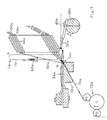
- Figures 1 to 3 show a first embodiment a warp knitting machine which in a knock-off bar 32 in guided and driven in their longitudinal direction back and forth Knitting needles 34, the warp thread guide 36th are upstream.
- the warp thread guides 36 are on a warp thread layer 38 attached and move around the knitting needles 34, each with a warp thread 40 in a knitting needle 34 to insert when this is in the foremost position located, as shown in dashed lines in Figure 1.
- the knitting needles 34 are in this embodiment as Carabiner needles designed and in a not shown, driven in a known manner.
- a package 42 is on a carrier 42 above the knitting needles 34 arranged from weft thread rods 44 with the numbers 1 to 24, that is held on the top by a guide 46 is.
- Each weft bar 44 includes a number of tubular weft guides 48 to 50 wefts Feed active point 52.
- Weft threading rods 44 serve, for example, grooves 54, in the springs 56 of the adjacent components engage.
- the individual Weft guide rods 44 by individual actuators 58, for example, electrically driven linear motors individually via corresponding gear 60 exclusively in the longitudinal direction driven back and forth.
- These actuators 58 are with an electronic, supported by a computer Control device 61 connected, which actuators 58th exemplary in terms of their use and / or stroke controls.
- feeders 62 For feeding the individual weft threads 50 to the knitting point 52 are feeders 62 which are arranged on a feeder rod 64 are up and in a manner not shown starting from the dashed starting position A can be moved into the active position W shown in solid lines.
- the feeders have and pass through a fork-like head 66 the weft guides 48 after their transfer finger-like to the staggered weft threads to the Take knitting point 52 and underlay knitting needles 34, before moving from the retracted position to the advanced position Position (shown in dashed lines in Figure 1) extended become.
- Weft threads for example, as stems S only in a chain K or as a partial shot over part of the width or as a long shot LS can be placed over the entire width of the knitted fabric 70.
- FIGS Another exemplary embodiment is shown in FIGS a warp knitting machine shown that essentially corresponds to that of Figures 1 to 3, so that the same parts are provided with the same reference numerals, but supplemented by the index a.
- the feeders 62a in turn have a fork-shaped head 66a, the one in the Wirknadelgasse 76 between the knitting needles 34a, the immersed part is provided with guide elevations 78, on the one hand the insertion of the feeders 62a into the knitting needle lanes 76 and on the other hand the knitting needles 34a to keep at a distance.
- the warp knitting machine of FIGS. 4 to 7 is further gone modified that the weft guide rods 44a and thus also the weft guide 48a with the carrier 42a and Guide 46a are arranged inclined to the horizontal, that the weft threads 50a run as freely as possible to the active point 52a.
- the tee bar 32a a band holder 80 is associated with the tee bar forms a guide gap 82 for the knitted fabric 70a which is withdrawn from the trigger device 72a.
- Figure 8 shows another warp knitting machine that is functional the warp knitting machines of FIGS. 1 to 7 above corresponds, so that the same parts with the same reference numerals but are provided with the index b.
- the knitting needles 34b arranged in knock-off bars 32b are preferably designed as carabiner needles.
- the tee bar 32b is associated with a band holder 80b, which with this forms a guide gap 82b.
- the knitting needles 34b are on a warp thread guide 36b arranged a warp thread guide 38b for Upstream feeding of warp threads 40b.
- the weft guide rods 44b with the weft guides 48b are arranged above the knitting needles 34b and in opposite directions to the direction in which the warp threads 40b of the knitting point 52b can be supplied.
- the arrangement of the weft thread rods 44b and the weft guide 48b hit that they lie in an arcuate path 86 in which also the feeders arranged on a feeder rod 64b 62b the thread guides 48b finger-like from the starting position A Walk through to the active position W.
- the drive device 74b for the feed bar 64b and the feeder 62b is designed such that the return path 75b for the fork-shaped head 66b of the feeder 62b outside the Weft guide 48b lies.
- the feeder rod is for this 64b is attached to a rocker arm 88 which is about the axis 90 swings, which in turn by means of a driven eccentric 92 describes the eccentric path 94, whereby the distance between the feeding arcuate path 86 through the weft guides 48b and the return path 75b distant therefrom becomes.
- the up and down movement is generated by a Eccentric drive 96, the eccentric 98 with a connecting rod 100 is connected, the other end of which is connected via a joint 102 the rocker arm 88 is coupled.
Landscapes
- Engineering & Computer Science (AREA)
- Textile Engineering (AREA)
- Knitting Machines (AREA)
- Looms (AREA)
Description
- Figur 1
- eine erste Kettenwirkmaschine mit angehobenem Zubringer im Vertikalschnitt;
- Figur 2
- die Kettenwirkmaschine der Figur 1 mit dem Zubringer in Ausgangsstellung, in Ansicht auf die Schussfadenlegestangen, im Ausschnitt;
- Figur 3
- die Kettenwirkmaschine der Figur 2 mit dem Zubringer an der Wirkstelle, in Ansicht auf die Schussfadenlegestangen, im Ausschnitt und in grösserem Massstab;
- Figur 4
- eine weitere Kettenwirkmaschine mit dem Zubringer in Ausgangsstellung, im Vertikalschnitt;
- Figur 5
- die Kettenwirkmaschine der Figur 4 mit dem Zubringer an der Wirkstelle, im Ausschnitt und in grösserem Massstab;
- Figur 6
- die Kettenwirkmaschine der Figur 5 im Grundriss;
- Figur 7
- die Kettenwirkmaschine der Figur 4 mit dem Zubringer auf dem Rückweg; und
- Figur 8
- eine weitere Kettenwirkmaschine mit längs einer bogenförmigen Fläche angeordneten Schussfadenlegestange, im Vertikalschnitt.
- A
- Ausgangsstellung
- LS
- Langschuss
- K
- Kette
- S
- Stengel
- W
- Wirkstellung
- 32
- Abschlagbalken
- 32a
- Abschlagbalken
- 32b
- Abschlagbalken
- 34
- Wirknadel
- 34a
- Wirknadel
- 34b
- Wirknadel
- 36
- Kettfadenführer
- 36a
- Kettfadenführer
- 36b
- Kettfadenführer
- 38
- Kettfadenleger
- 38a
- Kettfadenleger
- 38b
- Kettfadenleger
- 40
- Kettfaden
- 40a
- Kettfaden
- 40b
- Kettfaden
- 42
- Träger
- 42a
- Träger
- 44
- Schussfadenlegestange
- 44a
- Schussfadenlegestange
- 44b
- Schussfadenlegestange
- 46
- Führung
- 46a
- Führung
- 48
- Schussfadenführer
- 48a
- Schussfadenführer
- 48b
- Schussfadenführer
- 50
- Schussfaden
- 50a
- Schussfaden
- 50b
- Schussfaden
- 52
- Wirkstelle
- 52a
- Wirkstelle
- 52b
- Wirkstelle
- 54
- Nut
- 56
- Feder
- 58
- Aktuator
- 60
- Getriebe
- 61
- Steuervorrichtung
- 62
- Zubringer
- 62a
- Zubringer
- 62b
- Zubringer
- 64
- Zubringerstange
- 64a
- Zubringerstange
- 64b
- Zubringerstange
- 66
- Kopf gabelförmiger
- 66a
- Kopf gabelförmiger
- 66b
- Kopf gabelförmiger
- 68
- Warenrand
- 68a
- Warenrand
- 70
- Wirkware
- 70a
- Wirkware
- 70b
- Wirkware
- 72
- Abzugsvorrichtung
- 72a
- Abzugsvorrichtung
- 74
- Antriebsvorrichtung
- 74b
- Antriebsvorrichtung
- 75
- Rückweg
- 75b
- Rückweg
- 76
- Wirknadelgasse
- 78
- Führungserhebung
- 80
- Bandhalter
- 80b
- Bandhalter
- 82
- Führungsspalt
- 82b
- Führungsspalt
- 86
- Bahn bogenförmige
- 88
- Schwinghebel
- 90
- Achse
- 92
- Exzenter
- 94
- Exzenterweg
- 96
- Exzenterantrieb
- 98
- Exzenter
- 100
- Pleuelstange
- 102
- Gelenk
Claims (15)
- Kettenwirkmaschine, mit an einem Abschlagbalken (32,32a,32b) geführten Wirknadeln (34,34a,34b), denen Kettfadenleger (38,38a,38b) mit Kettfadenführern (36,36a,36b) vorgelagert und Schussfadenlegestangen (44,44a,44b) mit Schussfadenführern (48,48a,48b) zugeordnet sind, dadurch gekennzeichnet, dass die Schussfadenführer (48,48a,48b) der Schussfadenlegestangen (44, 44a,44b) die Bahn der Wirknadeln (34,34a,34b) nicht durchkreuzen und dass den Schussfadenführern (48,48a,48b) der Schussfadenlegestangen (44,44a,44b) Zubringer (62,62a,62b) zu den Wirknadeln (34,34a,34b) zugeordnet sind, die quer zur Versatzrichtung der Schussfadenlegestangen (44,44a,44b) zwischen den Schussfadenführern (48,48a,48b) und den Wirknadeln (34,34a,34b) derart auf- und abgehend geführt und antreibbar sind, dass die Zubringer (62,62a,62b) versetzt gelegte Schussfäden (50,50a,50b) den zugeordneten Wirknadeln (34,34a,34b) unterlegen.
- Kettenwirkmaschine nach Anspruch 1, dadurch gekennzeichnet, dass die Schussfadenlegestangen (44,44a,44b) mit den Schussfadenführern (48,48a,48b) nur in ihrer Versatzrichtung hin- und hergehend bewegbar sind.
- Kettenwirkmaschine nach Anspruch 1 oder 2, dadurch gekennzeichnet, dass die Wirknadel (34,34a,34b) nur in ihrer Wirkachse bewegbar ausgeführt ist.
- Kettenwirkmaschine nach einem der Ansprüche 1 bis 3, dadurch gekennzeichnet, dass jeder Wirknadel (34,34a,34b) ein Zubringer (62,62a,62b) zugeordnet ist.
- Kettenwirkmaschine nach einem der Ansprüche 1 bis 4, dadurch gekennzeichnet, dass die Zubringer (62,62a,62b) die Schussfadenführer (48,48a,48b) der Schussfadenlegestangen (44,44a,44b) und die Wirknadeln (34,34a,34b) fingerartig durchkreuzen.
- Kettenwirkmaschine nach einem der Ansprüche 1 bis 5, dadurch gekennzeichnet, dass die Zubringer (62,62a,62b) an einer gemeinsamen, antreibbaren Zubringerstange (64,64a, 64b) angeordnet sind.
- Kettenwirkmaschine nach einem der Ansprüche 1 bis 6, dadurch gekennzeichnet, dass der Rückweg (75,75b) des Zubringers (62a,62b) von der Wirkstelle mit Abstand von den Schussfadenführern (48a,48b) angeordnet ist.
- Kettenwirkmaschine nach einem der Ansprüche 1 bis 7, dadurch gekennzeichnet, dass die Schussfadenlegestangen (44a) mit den Schussfadenführern (48a) derart angeordnet sind, dass die Schussfäden (50a) durch die Schussfadenführer (48a) im wesentlichen in gleicher Richtung der Wirkstelle (52a) zugeführt sind wie die Kettfäden (40a).
- Kettenwirkmaschine nach einem der Ansprüche 1 bis 7, dadurch gekennzeichnet, dass die Schussfadenlegestangen (44,44b) mit den Schussfadenführern (48,48b) derart angeordnet sind, dass die Schussfäden (50,50b) durch die Schussfadenführer (48,48b) in der entgegengesetzten Richtung der Wirkstelle (52,52b) zugeführt sind wie die Kettfäden (40,40b).
- Kettenwirkmaschine nach einem der Ansprüche 1 bis 9, dadurch gekennzeichnet, dass die Schussfadenlegestangen (44,44a,44b) derart angeordnet sind, dass die Mündungen der Schussfadenführer (48,48a,48b) in einer geraden oder bogenförmigen Fläche zur Wirkstelle (52,52a,52b) angeordnet sind.
- Kettenwirkmaschine nach einem der Ansprüche 1 bis 10, dadurch gekennzeichnet, dass die Zubringer (62,62a,62b) einen nach unten offenen gabelförmigen Kopf (66,66a,66b) zum Erfassen der Schussfäden (50,50a,50b) aufweisen.
- Kettenwirkmaschine nach einem der Ansprüche 1 bis 11, dadurch gekennzeichnet, dass die Zubringer (62a) jeweils an einem zwischen die Wirknadeln (34a) in die Wirknadelgasse (76) eingreifenden Kopf (66a) beidseits Führungserhebungen (78) aufweisen.
- Kettenwirkmaschine nach einem der Ansprüche 1 bis 12, dadurch gekennzeichnet, dass die Zubringer (62,62a,62b) so ausgelegt sind, dass sie nach dem Durchkreuzen der Wirknadeln (34,34a,34b) die Schussfäden (50,50a,50b) an den Warenrand (68,68a) der Wirkware (70,70a) andrücken bzw. anschlagen.
- Kettenwirkmaschine nach einem der Ansprüche 1 bis 13, dadurch gekennzeichnet, dass die Schussfadenlegestangen (44,44a,44b) jeweils durch einen elektrischen Aktuator (58) antreibbar sind, der vorzugsweise mittels einer elektronischen Steuervorrichtung (61) steuerbar ist.
- Kettenwirkmaschine nach einem der Ansprüche 1 bis 14, dadurch gekennzeichnet, dass die auf- und abgehende Bewegung der Zubringer (62,62a) in ihrer Grösse einstellbar ist.
Applications Claiming Priority (3)
| Application Number | Priority Date | Filing Date | Title |
|---|---|---|---|
| CH179897 | 1997-07-25 | ||
| CH179897 | 1997-07-25 | ||
| PCT/CH1998/000288 WO1999005351A1 (de) | 1997-07-25 | 1998-07-02 | Kettenwirkmaschine, insbesondere häkelgalonmaschine |
Publications (2)
| Publication Number | Publication Date |
|---|---|
| EP0998601A1 EP0998601A1 (de) | 2000-05-10 |
| EP0998601B1 true EP0998601B1 (de) | 2002-02-06 |
Family
ID=4218855
Family Applications (1)
| Application Number | Title | Priority Date | Filing Date |
|---|---|---|---|
| EP98929184A Expired - Lifetime EP0998601B1 (de) | 1997-07-25 | 1998-07-02 | Kettenwirkmaschine, insbesondere häkelgalonmaschine |
Country Status (11)
| Country | Link |
|---|---|
| US (1) | US6209362B1 (de) |
| EP (1) | EP0998601B1 (de) |
| JP (1) | JP4128328B2 (de) |
| CN (1) | CN1079457C (de) |
| AU (1) | AU7904098A (de) |
| BR (1) | BR9811550B1 (de) |
| DE (1) | DE59803026D1 (de) |
| ES (1) | ES2169527T3 (de) |
| RU (1) | RU2190709C2 (de) |
| TW (1) | TW436546B (de) |
| WO (1) | WO1999005351A1 (de) |
Families Citing this family (9)
| Publication number | Priority date | Publication date | Assignee | Title |
|---|---|---|---|---|
| DE10041192C2 (de) * | 2000-08-23 | 2002-09-19 | Mayer Textilmaschf | Musterlegebarrenanordnung für Kettenwirkmaschinen |
| EP1520922B1 (de) * | 2003-09-30 | 2008-11-19 | Luigi Omodeo Zorini | Textilmaschine und deren Steuerung |
| ATE418635T1 (de) * | 2006-06-27 | 2009-01-15 | Luigi Omodeo Zorini | Häkelgalonmaschine |
| DE102006055497B4 (de) * | 2006-11-24 | 2009-01-02 | Karl Mayer Textilmaschinenfabrik Gmbh | Musterungshilfsvorrichtung einer Kettenwirkmaschine |
| CN104750048A (zh) * | 2013-12-31 | 2015-07-01 | 南京理工大学常熟研究院有限公司 | 一种嵌入式织带机集散控制系统 |
| ES2681446T3 (es) * | 2016-07-28 | 2018-09-13 | Karl Mayer Textilmaschinenfabrik Gmbh | Máquina de género de punto por urdimbre y procedimiento para la fabricación de un género de punto por urdimbre |
| KR101916013B1 (ko) * | 2017-07-12 | 2018-11-07 | 배차용 | 코로셋 머신 |
| CN108166149A (zh) * | 2018-02-08 | 2018-06-15 | 江苏佳成科技股份有限公司 | 高质量防损伤长毛纱钩编机 |
| CN114960019B (zh) * | 2022-07-18 | 2023-09-05 | 泉州众锦源精密机械有限公司 | 一种高速钩编机 |
Family Cites Families (7)
| Publication number | Priority date | Publication date | Assignee | Title |
|---|---|---|---|---|
| IT1067328B (it) * | 1976-12-28 | 1985-03-16 | Brevitex Ets Exploit | Perfezionamenti alle macchine a crochet,allo scopo di aumentarne la velocita' di lavoro |
| DE2706974C3 (de) * | 1977-02-18 | 1979-11-08 | Karl Mayer Textil-Maschinen-Fabrik Gmbh, 6053 Obertshausen | Kettenwirkmaschine mit mehreren teilschuOlegenden SchuBfadenführern |
| JPS5844779B2 (ja) * | 1979-06-20 | 1983-10-05 | 株式会社 武田機械 | 経編機に於ける編成装置 |
| DE3011963A1 (de) | 1980-03-25 | 1981-10-01 | Gebrüder Sulzer AG, 8401 Winterthur | Raschelmaschine |
| CH675135A5 (de) * | 1987-10-05 | 1990-08-31 | Textilma Ag | |
| DE9306474U1 (de) * | 1993-04-07 | 1993-06-24 | Textilma Ag, Hergiswil | Wirkmaschine, insbesondere Häkelgalonmaschine |
| DE4435562C2 (de) * | 1994-10-05 | 1998-12-17 | Mayer Textilmaschf | Legebarrenanordnung für eine Kettenwirkmaschine |
-
1998
- 1998-07-02 AU AU79040/98A patent/AU7904098A/en not_active Abandoned
- 1998-07-02 EP EP98929184A patent/EP0998601B1/de not_active Expired - Lifetime
- 1998-07-02 WO PCT/CH1998/000288 patent/WO1999005351A1/de not_active Ceased
- 1998-07-02 JP JP2000504315A patent/JP4128328B2/ja not_active Expired - Fee Related
- 1998-07-02 DE DE59803026T patent/DE59803026D1/de not_active Expired - Lifetime
- 1998-07-02 US US09/463,150 patent/US6209362B1/en not_active Expired - Fee Related
- 1998-07-02 RU RU2000102921/12A patent/RU2190709C2/ru not_active IP Right Cessation
- 1998-07-02 CN CN98807421A patent/CN1079457C/zh not_active Expired - Fee Related
- 1998-07-02 BR BRPI9811550-2A patent/BR9811550B1/pt not_active IP Right Cessation
- 1998-07-02 ES ES98929184T patent/ES2169527T3/es not_active Expired - Lifetime
- 1998-07-14 TW TW087111425A patent/TW436546B/zh not_active IP Right Cessation
Also Published As
| Publication number | Publication date |
|---|---|
| JP4128328B2 (ja) | 2008-07-30 |
| TW436546B (en) | 2001-05-28 |
| ES2169527T3 (es) | 2002-07-01 |
| BR9811550A (pt) | 2000-08-29 |
| US6209362B1 (en) | 2001-04-03 |
| RU2190709C2 (ru) | 2002-10-10 |
| HK1027137A1 (en) | 2001-01-05 |
| DE59803026D1 (de) | 2002-03-21 |
| BR9811550B1 (pt) | 2008-11-18 |
| CN1079457C (zh) | 2002-02-20 |
| AU7904098A (en) | 1999-02-16 |
| WO1999005351A1 (de) | 1999-02-04 |
| JP2001511488A (ja) | 2001-08-14 |
| EP0998601A1 (de) | 2000-05-10 |
| CN1264439A (zh) | 2000-08-23 |
Similar Documents
| Publication | Publication Date | Title |
|---|---|---|
| EP3347512B1 (de) | Webmaschine zur herstellung von webgut mit eingearbeiteten wirk- oder legefäden | |
| CH641851A5 (de) | Flachstrickmaschine. | |
| EP1120485B1 (de) | Webmaschine zum Herstellen eines Drehergewebes | |
| CH659835A5 (de) | Flachstrickmaschine mit nadelauswahleinrichtung. | |
| EP0998601B1 (de) | Kettenwirkmaschine, insbesondere häkelgalonmaschine | |
| DE69612200T2 (de) | Vorrichtung zum Einbringen von abwechselnd zwischengelegter Schussfäden an einer Häkelgalonmaschine und damit hergestellter Artikel | |
| EP3741892B1 (de) | Webmaschine zur herstellung von webgut mit eingearbeiteten effektfäden | |
| DE19802994C1 (de) | Verfahren und Vorrichtung zum Legen von einander unter verschiedenen Winkeln kreuzenden Diagonalfadenlagen | |
| DE19739540C1 (de) | Verfahren und Vorrichtung zur Herstellung einer gemusterten Wirkware | |
| DE9306474U1 (de) | Wirkmaschine, insbesondere Häkelgalonmaschine | |
| DE1585536B2 (de) | Kettenwirkmaschine zur spitzenherstellung | |
| DE3346246C2 (de) | Kettenwirkmaschine, insbesondere Häkelgalonmaschine | |
| DE102005013214A1 (de) | Vorrichtung sowie Verfahren zur Herstellung einer Kettenwirkware | |
| DE102011089657B4 (de) | Vorrichtung zum Aufbringen einer Fadenlage auf parallel laufende Förderketten | |
| EP0854949A1 (de) | Wirkmaschine, insbesondere kettenwirkmaschine | |
| EP0179072B1 (de) | Verfahren zur herstellung eines gemusterten kettengewirkes und kettenwirkmaschine zur ausführung des verfahrens | |
| WO1988002038A1 (fr) | Tissu tricote en chaine et metier a tricoter a fil de trame pour produire le tissu tricote en chaine | |
| EP0530488B1 (de) | Häkelgalonmaschine | |
| EP0937800B1 (de) | Verfahren zur Herstellung eines Gestricks auf einer Flachstrickmaschine | |
| DE4213354C2 (de) | Verfahren und EA-Platine zum Stricken eines RL-Gestrickes | |
| DE2460737C3 (de) | Vorrichtung in einer Nadelwebmaschine zur Herstellung von Bandgeweben mit Schußschlaufen | |
| DE1635760A1 (de) | Raschelwirkstuhl | |
| DD248709A3 (de) | Verfahren und flache kettenwirkmaschine zum herstellen eines schusskettengewirkes | |
| DE2027078C3 (de) | Verfahren zur Herstellung eines ReiBverschluBstreifens und Kettenwirkmaschine zur Durchführung des Verfahrens | |
| DE170736C (de) |
Legal Events
| Date | Code | Title | Description |
|---|---|---|---|
| PUAI | Public reference made under article 153(3) epc to a published international application that has entered the european phase |
Free format text: ORIGINAL CODE: 0009012 |
|
| 17P | Request for examination filed |
Effective date: 19991204 |
|
| AK | Designated contracting states |
Kind code of ref document: A1 Designated state(s): CH DE ES FR GB IT LI |
|
| GRAG | Despatch of communication of intention to grant |
Free format text: ORIGINAL CODE: EPIDOS AGRA |
|
| 17Q | First examination report despatched |
Effective date: 20010222 |
|
| GRAG | Despatch of communication of intention to grant |
Free format text: ORIGINAL CODE: EPIDOS AGRA |
|
| GRAH | Despatch of communication of intention to grant a patent |
Free format text: ORIGINAL CODE: EPIDOS IGRA |
|
| GRAH | Despatch of communication of intention to grant a patent |
Free format text: ORIGINAL CODE: EPIDOS IGRA |
|
| GRAA | (expected) grant |
Free format text: ORIGINAL CODE: 0009210 |
|
| REG | Reference to a national code |
Ref country code: GB Ref legal event code: IF02 |
|
| AK | Designated contracting states |
Kind code of ref document: B1 Designated state(s): CH DE ES FR GB IT LI |
|
| REG | Reference to a national code |
Ref country code: CH Ref legal event code: EP |
|
| REG | Reference to a national code |
Ref country code: CH Ref legal event code: NV Representative=s name: SCHMAUDER & PARTNER AG PATENTANWALTSBUERO |
|
| GBT | Gb: translation of ep patent filed (gb section 77(6)(a)/1977) |
Effective date: 20020207 |
|
| REF | Corresponds to: |
Ref document number: 59803026 Country of ref document: DE Date of ref document: 20020321 |
|
| ET | Fr: translation filed | ||
| REG | Reference to a national code |
Ref country code: ES Ref legal event code: FG2A Ref document number: 2169527 Country of ref document: ES Kind code of ref document: T3 |
|
| PLBE | No opposition filed within time limit |
Free format text: ORIGINAL CODE: 0009261 |
|
| STAA | Information on the status of an ep patent application or granted ep patent |
Free format text: STATUS: NO OPPOSITION FILED WITHIN TIME LIMIT |
|
| 26N | No opposition filed |
Effective date: 20021107 |
|
| PGFP | Annual fee paid to national office [announced via postgrant information from national office to epo] |
Ref country code: CH Payment date: 20080715 Year of fee payment: 11 |
|
| PGFP | Annual fee paid to national office [announced via postgrant information from national office to epo] |
Ref country code: GB Payment date: 20080722 Year of fee payment: 11 |
|
| REG | Reference to a national code |
Ref country code: CH Ref legal event code: PCAR Free format text: SCHMAUDER & PARTNER AG PATENT- UND MARKENANWAELTE VSP;ZWAENGIWEG 7;8038 ZUERICH (CH) |
|
| PGFP | Annual fee paid to national office [announced via postgrant information from national office to epo] |
Ref country code: FR Payment date: 20090716 Year of fee payment: 12 |
|
| REG | Reference to a national code |
Ref country code: CH Ref legal event code: PL |
|
| GBPC | Gb: european patent ceased through non-payment of renewal fee |
Effective date: 20090702 |
|
| PG25 | Lapsed in a contracting state [announced via postgrant information from national office to epo] |
Ref country code: LI Free format text: LAPSE BECAUSE OF NON-PAYMENT OF DUE FEES Effective date: 20090731 Ref country code: CH Free format text: LAPSE BECAUSE OF NON-PAYMENT OF DUE FEES Effective date: 20090731 |
|
| PG25 | Lapsed in a contracting state [announced via postgrant information from national office to epo] |
Ref country code: GB Free format text: LAPSE BECAUSE OF NON-PAYMENT OF DUE FEES Effective date: 20090702 |
|
| REG | Reference to a national code |
Ref country code: FR Ref legal event code: ST Effective date: 20110331 |
|
| PG25 | Lapsed in a contracting state [announced via postgrant information from national office to epo] |
Ref country code: FR Free format text: LAPSE BECAUSE OF NON-PAYMENT OF DUE FEES Effective date: 20100802 |
|
| PGFP | Annual fee paid to national office [announced via postgrant information from national office to epo] |
Ref country code: IT Payment date: 20120724 Year of fee payment: 15 Ref country code: ES Payment date: 20120726 Year of fee payment: 15 Ref country code: DE Payment date: 20120720 Year of fee payment: 15 |
|
| PG25 | Lapsed in a contracting state [announced via postgrant information from national office to epo] |
Ref country code: DE Free format text: LAPSE BECAUSE OF NON-PAYMENT OF DUE FEES Effective date: 20140201 |
|
| REG | Reference to a national code |
Ref country code: DE Ref legal event code: R119 Ref document number: 59803026 Country of ref document: DE Effective date: 20140201 |
|
| PG25 | Lapsed in a contracting state [announced via postgrant information from national office to epo] |
Ref country code: IT Free format text: LAPSE BECAUSE OF NON-PAYMENT OF DUE FEES Effective date: 20130702 |
|
| REG | Reference to a national code |
Ref country code: ES Ref legal event code: FD2A Effective date: 20140905 |
|
| PG25 | Lapsed in a contracting state [announced via postgrant information from national office to epo] |
Ref country code: ES Free format text: LAPSE BECAUSE OF NON-PAYMENT OF DUE FEES Effective date: 20130703 |