EP0995901A1 - Kraftstoffeinspritzventil - Google Patents
Kraftstoffeinspritzventil Download PDFInfo
- Publication number
- EP0995901A1 EP0995901A1 EP99307865A EP99307865A EP0995901A1 EP 0995901 A1 EP0995901 A1 EP 0995901A1 EP 99307865 A EP99307865 A EP 99307865A EP 99307865 A EP99307865 A EP 99307865A EP 0995901 A1 EP0995901 A1 EP 0995901A1
- Authority
- EP
- European Patent Office
- Prior art keywords
- fuel
- piezoelectric actuator
- fuel injector
- control piston
- actuator
- Prior art date
- Legal status (The legal status is an assumption and is not a legal conclusion. Google has not performed a legal analysis and makes no representation as to the accuracy of the status listed.)
- Granted
Links
- 239000000446 fuel Substances 0.000 title claims abstract description 90
- 239000011248 coating agent Substances 0.000 claims description 8
- 238000000576 coating method Methods 0.000 claims description 8
- 239000000565 sealant Substances 0.000 claims description 5
- 238000002347 injection Methods 0.000 description 17
- 239000007924 injection Substances 0.000 description 17
- 230000000694 effects Effects 0.000 description 7
- 238000005553 drilling Methods 0.000 description 6
- 239000000853 adhesive Substances 0.000 description 3
- 230000001070 adhesive effect Effects 0.000 description 3
- 230000005540 biological transmission Effects 0.000 description 2
- 238000002485 combustion reaction Methods 0.000 description 2
- 238000004519 manufacturing process Methods 0.000 description 2
- 229920002530 polyetherether ketone Polymers 0.000 description 2
- 239000012812 sealant material Substances 0.000 description 2
- 125000006850 spacer group Chemical group 0.000 description 2
- 230000004323 axial length Effects 0.000 description 1
- 229910010293 ceramic material Inorganic materials 0.000 description 1
- 230000006835 compression Effects 0.000 description 1
- 238000007906 compression Methods 0.000 description 1
- 239000000356 contaminant Substances 0.000 description 1
- 229920003247 engineering thermoplastic Polymers 0.000 description 1
- 239000012212 insulator Substances 0.000 description 1
- 239000000463 material Substances 0.000 description 1
- 230000003071 parasitic effect Effects 0.000 description 1
- 238000007789 sealing Methods 0.000 description 1
- 238000011144 upstream manufacturing Methods 0.000 description 1
Images

Classifications
-
- F—MECHANICAL ENGINEERING; LIGHTING; HEATING; WEAPONS; BLASTING
- F02—COMBUSTION ENGINES; HOT-GAS OR COMBUSTION-PRODUCT ENGINE PLANTS
- F02M—SUPPLYING COMBUSTION ENGINES IN GENERAL WITH COMBUSTIBLE MIXTURES OR CONSTITUENTS THEREOF
- F02M51/00—Fuel-injection apparatus characterised by being operated electrically
- F02M51/06—Injectors peculiar thereto with means directly operating the valve needle
- F02M51/0603—Injectors peculiar thereto with means directly operating the valve needle using piezoelectric or magnetostrictive operating means
-
- F—MECHANICAL ENGINEERING; LIGHTING; HEATING; WEAPONS; BLASTING
- F02—COMBUSTION ENGINES; HOT-GAS OR COMBUSTION-PRODUCT ENGINE PLANTS
- F02M—SUPPLYING COMBUSTION ENGINES IN GENERAL WITH COMBUSTIBLE MIXTURES OR CONSTITUENTS THEREOF
- F02M51/00—Fuel-injection apparatus characterised by being operated electrically
-
- F—MECHANICAL ENGINEERING; LIGHTING; HEATING; WEAPONS; BLASTING
- F02—COMBUSTION ENGINES; HOT-GAS OR COMBUSTION-PRODUCT ENGINE PLANTS
- F02M—SUPPLYING COMBUSTION ENGINES IN GENERAL WITH COMBUSTIBLE MIXTURES OR CONSTITUENTS THEREOF
- F02M47/00—Fuel-injection apparatus operated cyclically with fuel-injection valves actuated by fluid pressure
- F02M47/02—Fuel-injection apparatus operated cyclically with fuel-injection valves actuated by fluid pressure of accumulator-injector type, i.e. having fuel pressure of accumulator tending to open, and fuel pressure in other chamber tending to close, injection valves and having means for periodically releasing that closing pressure
-
- F—MECHANICAL ENGINEERING; LIGHTING; HEATING; WEAPONS; BLASTING
- F02—COMBUSTION ENGINES; HOT-GAS OR COMBUSTION-PRODUCT ENGINE PLANTS
- F02M—SUPPLYING COMBUSTION ENGINES IN GENERAL WITH COMBUSTIBLE MIXTURES OR CONSTITUENTS THEREOF
- F02M51/00—Fuel-injection apparatus characterised by being operated electrically
- F02M51/005—Arrangement of electrical wires and connections, e.g. wire harness, sockets, plugs; Arrangement of electronic control circuits in or on fuel injection apparatus
-
- F—MECHANICAL ENGINEERING; LIGHTING; HEATING; WEAPONS; BLASTING
- F02—COMBUSTION ENGINES; HOT-GAS OR COMBUSTION-PRODUCT ENGINE PLANTS
- F02M—SUPPLYING COMBUSTION ENGINES IN GENERAL WITH COMBUSTIBLE MIXTURES OR CONSTITUENTS THEREOF
- F02M61/00—Fuel-injectors not provided for in groups F02M39/00 - F02M57/00 or F02M67/00
- F02M61/16—Details not provided for in, or of interest apart from, the apparatus of groups F02M61/02 - F02M61/14
- F02M61/20—Closing valves mechanically, e.g. arrangements of springs or weights or permanent magnets; Damping of valve lift
- F02M61/205—Means specially adapted for varying the spring tension or assisting the spring force to close the injection-valve, e.g. with damping of valve lift
Definitions
- This invention relates to a fuel injector for use in the delivery of fuel to a combustion space of an internal combustion engine.
- the invention relates to a fuel injector of the type intended for use in a fuel system of the accumulator or common rail type, the injector being of the type controlled using a piezoelectric actuator.
- a piezoelectric actuator is operable to control the position occupied by a control piston, the piston being moveable to control the fuel pressure within a control chamber defined, in part, by a surface associated with the valve needle of the injector to control movement of the injector.
- a piezoelectrically actuable fuel injector comprising a fuel inlet arranged, in use, to receive fuel under high pressure from a source of pressurized fuel, an outlet, and an accumulator volume located between the inlet and the outlet, a piezoelectric actuator being located within the accumulator volume and being operable to move a control piston to modify the fuel pressure within a control chamber.
- Such an arrangement is advantageous in that the end of the control piston remote from the control chamber may be exposed to fuel at high pressure.
- the fuel pressure drop along the length of the piston may therefore be reduced, and as a result leakage of fuel from the control chamber can be reduced.
- the injector with such an accumulator volume, depending upon the capacity of the accumulator volume, the effect of the fall in fuel pressure due to the fuel passages and lines upstream of the fuel inlet can be reduced.
- An articulated connection is conveniently provided between the actuator and the control piston. Such an arrangement permits compensation for slight manufacturing inaccuracies.
- the articulated connection is conveniently arranged to permit the application of a retracting force to the piston upon energizing the actuator in such a manner as to reduce the length thereof. This is conveniently achieved by arranging for a seal to be formed between the actuator and the piston such that, upon the length of the actuator being reduced, a partial vacuum is drawn in a volume between the actuator and the piston serving to draw the piston to follow the movement of the end of the actuator.
- the volume between the piston and the actuator may communicate with the control chamber, if desired.
- the actuator is conveniently provided with a flexible sealant coating, preferably an electronics conformal sealant coating.
- a flexible sealant coating preferably an electronics conformal sealant coating.
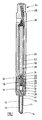
- the fuel injector illustrated in the accompanying drawings comprises a nozzle body 10 provided with a blind bore 11 within which a valve needle 12 is reciprocable.
- the valve needle 12 is shaped for engagement with a seating defined adjacent the blind end of the bore 11.
- the needle 12 is of stepped form, including a relatively large diameter region which is of diameter substantially equal to that of the adjacent part of the bore 11 and arranged to guide the needle 12 for sliding movement within the bore 11, and a reduced diameter portion which defines, with the bore 11, a delivery chamber 13. It will be appreciated that engagement of the needle 12 with the seating controls communication between the delivery chamber 13 and one or more outlets openings 14 located downstream of the seating.
- the bore 11 is shaped to define an annular gallery 15 which communicates with a drilling 16 provided in the nozzle body.
- the needle 12 is provided with flutes 17 defining flow paths between the annular gallery 15 and the delivery chamber 13.
- the needle 12 defines an angled step at the interconnection of the relatively large and smaller diameter regions thereof, the step forming a thrust surface which is exposed to the fuel pressure within the delivery chamber 13 such that when fuel under high pressure is applied to the delivery chamber 13, the action of the fuel applies a force to the needle 12 urging the needle 12 away from its seating.
- the exposed end surface of the needle 12 similarly forms a thrust surface against which fuel under pressure may act to urge the needle towards its seating.
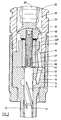
- the nozzle body 10 abuts a distance piece 18 provided with a through bore within which a piston member 19 of tubular form is slidable.
- a screw-threaded rod 20 is engaged within the passage defined by the tubular piston member, a spring 21 being engaged between the screw-threaded rod 20 and the end surface of the valve needle 12.
- the spring 21 applies a biasing force to the needle 12, urging the needle 12 towards its seating. It will be appreciated that for a given position of the piston member 19, adjustment of the axial position of the screw-threaded rod 20 by rotating the rod 20 relative to the piston member 19 will vary the spring force applied by the spring 21 to the needle 12.
- the distance piece 18 abuts an end of an actuator housing 23 which is of elongate form and is provided with a bore defining an accumulator 22.
- the actuator housing 23 is provided with an inlet region 24 arranged to be coupled to a high pressure fuel line (not shown) to permit connection of the fuel injector to a source of fuel under high pressure, for example a common rail charged to an appropriate high pressure by a suitable high pressure fuel pump.
- the inlet region 24 houses an edge filter member 25 to remove particulate contaminants from the flow of fuel to the injector, in use, thereby reducing the risk of damage to the various components of the injector.
- the clean side of the filter formed by the edge filter member 25 communicates through a drilling 26 with the accumulator 22.
- a drilling 27 provided in the distance piece 18 permits communication between the accumulator 22 and the drilling 16 provided in the nozzle body 10.
- a cap nut 28 is used to secure the nozzle body 10 and distance piece 18 to the actuator housing 23.
- a piezoelectric actuator stack 29 is located within the accumulator 22.
- the actuator stack 29 may be provided with a coating 30 of a flexible sealant material, the sealant material being of an electronics conformal nature.
- the coating 30 acts to prevent or restrict the ingress of fuel into the joints between the individual elements forming the piezoelectric actuator stack 29, thus reducing the risk of damage to the actuator stack 29. Further, as the stack is subject to the compressive load applied by the fuel under pressure, the risk of propagation of cracks is reduced.
- the actuator stack 29 carries, at its lower end, an anvil member 31 which is shaped to define a part-spherical recess.
- a load transmitting member 32 including a region of part-spherical form extends into the part-spherical recess of the anvil member 31.
- the load transmitting member 32 is provided with an axially extending, screw-threaded passage within which the screw-threaded rod 20 engages.
- a spacer or shim 33 is located between the load transmitting member 32 and the adjacent face of the tubular piston member 19 to control the spacing of these components.
- the screw threaded rod 20 is shaped to receive a tool for use in rotating the rod 20 to adjust the spring force applied to the needle 12.
- the radius of curvature of the pan-spherical surface of the load transmitting member 32 is slightly greater than that of the part-spherical recess of the anvil member 31. It will be appreciated, therefore, that the engagement between these components occurs around a substantially circular sealing line adjacent the outer periphery of the anvil member 31, and that a small volume is defined between these components.
- the cooperation between the anvil member 31 and load transmitting member 32 is such as to define an imperfect seal between these components, the seal being sufficient to restrict the rate at which fuel can flow to the volume defined therebetween from the accumulator 22.
- the upper end of the actuator stack 29 is secured to a first terminal member 34 using an appropriate adhesive, an insulating spacer member 35 being located between the first terminal member 34 and the end surface of the actuator stack 29.
- a second, outer terminal member 36 surrounds a stem 34 a of the first terminal member 34, another insulator member 37 being located between the first and second terminal members. Again, a suitable adhesive is conveniently used to secure these integers to one another.
- a seal member 38 engages around part of the second terminal member 36.
- the seal member 38 includes a surface of part-spherical or part-spheroidal form which is arranged to seat within a correspondingly shaped recess formed around a drilling which opens into an end of the accumulator 22, to compensate for slight misalignments and manufacturing inaccuracies.
- the first and second terminals 34, 36 extend into a radial drilling 39 provided in the actuator housing 23 whereby appropriate electrical connections can be made to permit control of the piezoelectric actuator.
- the fuel pressure within the accumulator assists the
- the seal member 38 may be constructed from a high performance engineering thermoplastics material such as Poly Ethyl Ether Ketone (PEEK), PPS or LCP, or may be constructed from a ceramic material.
- PEEK Poly Ethyl Ether Ketone
- PPS Poly Ethyl Ether Ketone
- the end surface of the needle 12 which engages the spring 21 is exposed to the fuel pressure within a control chamber 40 defined between the nozzle body 10, the distance piece 18, the piston member 19 and the screw-threaded rod 20. It will be appreciated that the fuel pressure within the control chamber 40 assists the spring 21 in applying a force to the needle 12 urging the needle 12 towards its seating.
- the piston member 19 occupies a position in which the fuel within the control chamber 40 is pressurized to an extent sufficient to ensure that the force applied to the needle 12 by the fuel under pressure within the control chamber 40 in conjunction with the action of the spring 21 is sufficient to hold the needle 12 in engagement with its seating against the action of the fuel under pressure within the delivery chamber 13. It will be appreciated, therefore, that injection of fuel is not taking place.
- the fuel pressure within the accumulator 22 is high, thus a relatively small pressure drop occurs along the length of the piston member 19. As a result, leakage of fuel between the piston member 19 and the distance piece 18 from the control chamber 40 to the accumulator 22 is restricted to a low level.
- the distance piece 18 is shaped to include a region 18 a of reduced diameter which extends into the accumulator 22.
- the fuel under pressure within the accumulator 22 acts upon the outer surface of this part of the distance piece 18 applying a radial compressive load to the distance piece 18, and a result, leakage of fuel between the piston member 19 and the distance piece 18 is further restricted.
- the actuator stack 29 is operated to move to a second energization state in which it is of reduced axial length. Since the upper end of the actuator stack 29, in the orientation illustrated, is held in a fixed position relative to the actuator housing 23, the change in energization state of the stack 29 to reduce the length thereof results in upward movement of the lower end of the stack 29. The movement of the lower end of the actuator stack 29 is transmitted to the anvil 31. As a seal is formed between the anvil 31 and the load transmitting member 32, the movement of the anvil member 31 reduces the fuel pressure within the volume defined between these components, the reduced fuel pressure serving to draw the load transmitting member 32 to move with the stack 29.
- the stack 29 is returned to its original energization state, and as a result the anvil 31 and load transmitting member 32 are pushed in a downward direction returning the piston member 19 to substantially its original position.
- the fuel pressure within the control chamber 40 increases, thus applying a greater magnitude force to the needle 12, and a point will be reached beyond which the fuel pressure within the control chamber 40 in conjunction with the spring 21 is able to return the needle 12 into engagement with its seating.
- the volume between the anvil 31 and the load transmitting member 32 communicates with the control chamber 40, conveniently through the screw-threaded engagement between the piston member 19 and the rod 20, and between the rod 20 and the load transmitting member 32.
- the volume between the anvil 31 and the load transmitting member 32 is held at a relatively low pressure, between the accumulator pressure and the control chamber pressure, the control chamber 40 being at a relatively low pressure, thus any leakage of fuel to the volume from the accumulator 22 is of little effect.
- the communication between the volume defined between the anvil 31 and the load transmitting member 32 and the control chamber 40 may be broken.
- leakage of fuel to the volume from the accumulator 22 will gradually reduce the partial vacuum drawn therebetween, and as a result, if injection is not terminated within a predetermined time, for example upon the failure of the piezoelectric stack 29, then the load transmitting member 32 will separate from the anvil 31, and the fuel pressure within the accumulator 22 will return the piston member 19 to a position in which the fuel pressure within the control chamber 40 is sufficient to return the needle 12 into engagement with its seating. It will be appreciated, therefore, that a second fail-safe may be provided.
- the embodiment described hereinbefore is advantageous in that an accumulator is provided between the inlet arrangement 24 and the outlets 14 of the injector.
- a further advantage of the arrangement described hereinbefore is that pressure waves transmitted along the high pressure fuel line, for example reflected waves occurring after termination of injection, will arrive at the delivery chamber 13 very shortly after their transmission to the accumulator 22.
- pressure waves transmitted along the high pressure fuel line for example reflected waves occurring after termination of injection
- the effect of the pressure waves upon the needle 12 and the piston member 19 urging the piston member 19 in an upward direction in the orientation illustrated will be countered by the effect of the pressure waves within the accumulator 22 urging the piston member 19 in a downward direction to increase the fuel pressure within the control chamber 40.
- the risk of secondary injection of fuel as a result of the transmission of such reflected waves may thus be reduced.
- the injector described hereinbefore is suitable for use in applications in which the injector must be of relatively small diameter. In such applications, the stresses applied to the various components are sufficient that it is not practical to use one or more dowels to ensure that the various components are properly aligned. In order to avoid the use of such dowels, and permit correct orientation of the various components, the nozzle body 10 is conveniently provided with a slot or groove 41 or an alternative identification feature which is accessible once the injector has been assembled to permit determination of the orientation of the nozzle body 10.
Landscapes
- Engineering & Computer Science (AREA)
- Chemical & Material Sciences (AREA)
- Combustion & Propulsion (AREA)
- Mechanical Engineering (AREA)
- General Engineering & Computer Science (AREA)
- Physics & Mathematics (AREA)
- Fluid Mechanics (AREA)
- Fuel-Injection Apparatus (AREA)
Applications Claiming Priority (2)
| Application Number | Priority Date | Filing Date | Title |
|---|---|---|---|
| GBGB9823028.7A GB9823028D0 (en) | 1998-10-22 | 1998-10-22 | Fuel injector |
| GB9823028 | 1998-10-22 |
Publications (2)
| Publication Number | Publication Date |
|---|---|
| EP0995901A1 true EP0995901A1 (de) | 2000-04-26 |
| EP0995901B1 EP0995901B1 (de) | 2003-01-29 |
Family
ID=10841007
Family Applications (1)
| Application Number | Title | Priority Date | Filing Date |
|---|---|---|---|
| EP99307865A Expired - Lifetime EP0995901B1 (de) | 1998-10-22 | 1999-10-06 | Kraftstoffeinspritzventil |
Country Status (7)
| Country | Link |
|---|---|
| US (1) | US6234404B1 (de) |
| EP (1) | EP0995901B1 (de) |
| JP (2) | JP4674928B2 (de) |
| KR (1) | KR20000029217A (de) |
| DE (1) | DE69905116T2 (de) |
| ES (1) | ES2192366T3 (de) |
| GB (1) | GB9823028D0 (de) |
Cited By (34)
| Publication number | Priority date | Publication date | Assignee | Title |
|---|---|---|---|---|
| EP1096136A2 (de) * | 1999-10-29 | 2001-05-02 | Delphi Technologies, Inc. | Kraftstoffeinspritzventil |
| DE10053928A1 (de) * | 2000-10-31 | 2002-05-29 | Siemens Ag | Einspritzventil mit einem Mittel zum Fernhalten von Kraftstoff von einer Aktoreinheit |
| DE10307003B3 (de) * | 2003-02-19 | 2004-05-13 | Siemens Ag | Einspritzventil für die Einspritzung von Kraftstoff in eine Verbrennungskraftmaschine |
| WO2004081367A1 (de) * | 2003-03-12 | 2004-09-23 | Robert Bosch Gmbh | Brennstoffeinspritzventil |
| DE10333690A1 (de) * | 2003-07-24 | 2005-02-17 | Robert Bosch Gmbh | Kraftstoffeinspritzvorrichtung |
| US6889913B2 (en) | 1999-03-20 | 2005-05-10 | Robert Bosch Gmbh | Fuel injector |
| EP1574702A1 (de) * | 2004-03-11 | 2005-09-14 | Delphi Technologies, Inc. | Verfahren zum Zusammenbau eines Kraftstoffeinspritzventils |
| EP1596058A1 (de) * | 2004-05-14 | 2005-11-16 | Delphi Technologies, Inc. | Steckverbinderanordnung |
| EP1705369A1 (de) | 2005-03-01 | 2006-09-27 | Robert Bosch Gmbh | Kraftstoffinjektor für Verbrennungskraftmaschinen |
| EP1757803A1 (de) | 2005-08-24 | 2007-02-28 | Delphi Technologies, Inc. | Einspritzdüse |
| WO2007023049A1 (de) | 2005-08-26 | 2007-03-01 | Robert Bosch Gmbh | Kraftstoffinjektor mit direkter nadelsteuerung |
| EP1783842A1 (de) | 2005-11-04 | 2007-05-09 | Delphi Technologies, Inc. | Aktuatoranordnung |
| EP1811583A1 (de) | 2006-01-23 | 2007-07-25 | Delphi Technologies, Inc. | Piezoelektrischer Aktor |
| EP1813802A1 (de) | 2006-01-30 | 2007-08-01 | Delphi Technologies, Inc. | Piezoelektrischer Aktuator |
| WO2007102088A2 (en) | 2006-03-06 | 2007-09-13 | Delphi Technologies, Inc. | Encapsulating arrangement for an electrical component |
| EP1868253A2 (de) * | 2005-02-03 | 2007-12-19 | Delphi Technologies, Inc. | Piezoelektrischer Aktor |
| EP1956229A1 (de) | 2007-02-09 | 2008-08-13 | Delphi Technologies, Inc. | Piezoelektrischer Aktuator und Gehäuse dafür |
| EP1962351A1 (de) * | 2007-02-22 | 2008-08-27 | Robert Bosch Gmbh | Piezoaktormodul mit einer Kabeldurchführung |
| WO2008101782A1 (de) * | 2007-02-20 | 2008-08-28 | Robert Bosch Gmbh | Kraftstoffeinspritzventil zur kraftstoffeinspritzung in brennkraftmaschinen |
| EP2050951A1 (de) | 2007-10-18 | 2009-04-22 | Delphi Technologies, Inc. | Kraftstoffeinspritzdüse |
| EP2071178A1 (de) | 2007-12-10 | 2009-06-17 | Delphi Technologies, Inc. | Einspritzdüse |
| EP2083158A1 (de) | 2008-01-22 | 2009-07-29 | Delphi Technologies, Inc. | Piezoelektrisch betätigtes Kraftstoffeinspritzventil und Betriebsverfahren dafür |
| EP2128415A1 (de) | 2008-05-27 | 2009-12-02 | Delphi Technologies, Inc. | Verbesserungen einer Steuerung von Kraftstoffeinspritzdüsen |
| EP2224123A1 (de) | 2009-02-25 | 2010-09-01 | Delphi Technologies Holding S.à.r.l. | Piezoelektrischer Aktor |
| WO2010145911A1 (en) | 2009-06-15 | 2010-12-23 | Delphi Technologies Holding S.À.R.L. | Fuel injector |
| WO2011012519A1 (en) | 2009-07-29 | 2011-02-03 | Delphi Technologies Holding S.À.R.L. | Fuel injector |
| EP2295785A1 (de) | 2009-07-29 | 2011-03-16 | Delphi Technologies Holding S.à.r.l. | Kraftstoffeinspritzdüse |
| EP2372139A1 (de) | 2010-03-25 | 2011-10-05 | Delphi Technologies Holding S.à.r.l. | Aktuatoranordnung zur Verwendung mit einem Kraftstoffinjektor |
| EP2378107A1 (de) | 2010-04-19 | 2011-10-19 | Delphi Technologies Holding S.à.r.l. | Aktuatoranordnung zur Verwendung mit einem Kraftstoffinjektor |
| EP2426749A1 (de) | 2010-09-01 | 2012-03-07 | Delphi Technologies Holding S.à.r.l. | Aktuatoranordnung zur Verwendung mit einem Kraftstoffinjektor |
| EP2476896A1 (de) | 2011-01-13 | 2012-07-18 | Delphi Automotive Systems Luxembourg SA | Aktuatoranordnung zur Verwendung mit einem Kraftstoffinjektor |
| US20140048041A1 (en) * | 2011-02-25 | 2014-02-20 | Keihin Corporation | In-cylinder pressure detecting device of direct injection type internal combustion engine |
| WO2015110450A1 (en) * | 2014-01-27 | 2015-07-30 | Delphi International Operations Luxembourg S.À R.L. | Seal arrangement for a fuel injector actuator |
| US9897058B2 (en) | 2009-07-29 | 2018-02-20 | Delphi International Operations S.A.R.L. | Fuel injector |
Families Citing this family (21)
| Publication number | Priority date | Publication date | Assignee | Title |
|---|---|---|---|---|
| DE19901057A1 (de) * | 1999-01-14 | 2000-07-27 | Bosch Gmbh Robert | Kraftstoffeinspritzventil für Brennkraftmaschinen |
| US6520423B1 (en) * | 2000-03-21 | 2003-02-18 | Delphi Technologies, Inc. | Hydraulic intensifier assembly for a piezoelectric actuated fuel injector |
| DE10014737A1 (de) * | 2000-03-24 | 2001-10-11 | Bosch Gmbh Robert | Verfahren zur Bestimmung des Raildrucks eines Einspritzventils mit einem piezoelektrischen Aktor |
| ITTO20010539A1 (it) * | 2001-06-05 | 2002-12-05 | Fiat Ricerche | Iniettore di combustibile per un motore a combustione interna. |
| JP2003097418A (ja) * | 2001-07-18 | 2003-04-03 | Denso Corp | 圧電体素子の変位伝達構造 |
| EA008903B1 (ru) * | 2002-04-19 | 2007-08-31 | Марк У. Хатчинсон | Способ определения глубины скважины |
| US6760212B2 (en) * | 2002-09-23 | 2004-07-06 | Delphi Technologies, Inc. | Piezoelectric injector drive circuit |
| US6811093B2 (en) * | 2002-10-17 | 2004-11-02 | Tecumseh Products Company | Piezoelectric actuated fuel injectors |
| DE102004022958A1 (de) * | 2004-05-10 | 2005-12-22 | Siemens Ag | Kraftstoffinjektor mit einer korrigierbaren Einstellung eines Leerhubs einer Aktoreinheit |
| DE102004046888A1 (de) * | 2004-09-28 | 2006-03-30 | Robert Bosch Gmbh | Injektor zur Kraftstoffeinspritzung an einer Brennkraftmaschine |
| JP4502940B2 (ja) * | 2004-11-29 | 2010-07-14 | 京セラ株式会社 | 圧電素子用支持部材およびこれを用いた燃料噴射ノズルの駆動部 |
| EP1788232A1 (de) | 2005-11-16 | 2007-05-23 | Siemens Aktiengesellschaft | Aktorvorrichtung und Fluidinjektor |
| DE102006012845A1 (de) * | 2006-03-21 | 2007-10-04 | Daimlerchrysler Ag | Injektor für Speichereinspritzsysteme |
| US7552717B2 (en) | 2007-08-07 | 2009-06-30 | Delphi Technologies, Inc. | Fuel injector and method for controlling fuel injectors |
| JP5195451B2 (ja) * | 2008-04-15 | 2013-05-08 | 株式会社デンソー | 燃料噴射装置、それに用いられる蓄圧式燃料噴射装置システム |
| JP5093122B2 (ja) * | 2009-01-08 | 2012-12-05 | 株式会社デンソー | 燃料噴射装置 |
| EP2343746B1 (de) | 2010-01-11 | 2012-10-24 | Delphi Technologies Holding S.à.r.l. | Verfahren zur Verkapselung eines Aktuators mit einem piezoelektrischen Aktuatorstapel |
| WO2013183306A1 (ja) * | 2012-06-08 | 2013-12-12 | 本田技研工業株式会社 | 燃料噴射装置 |
| JP7022513B2 (ja) * | 2017-03-24 | 2022-02-18 | 日本ルメンタム株式会社 | 光送信モジュール、光モジュール、及び光伝送装置、並びにそれらの製造方法 |
| US10371110B2 (en) * | 2017-12-21 | 2019-08-06 | Caterpillar Inc. | Fuel injector having particulate-blocking perforation array |
| KR102653135B1 (ko) | 2024-01-18 | 2024-04-01 | (주)피에이엔지니어링 | 속도 감지에 따른 보조 바퀴 제어가 가능한 전동 킥보드 |
Citations (4)
| Publication number | Priority date | Publication date | Assignee | Title |
|---|---|---|---|---|
| DE1751543A1 (de) * | 1968-06-15 | 1970-08-27 | Kloeckner Humboldt Deutz Ag | Elektrisch steuerbares Einspritzventil |
| US4579283A (en) * | 1983-06-16 | 1986-04-01 | Nippon Soken, Inc. | Pressure responsive fuel injector actuated by pump |
| US4725002A (en) * | 1985-09-17 | 1988-02-16 | Robert Bosch Gmbh | Measuring valve for dosing liquids or gases |
| EP0324905A1 (de) * | 1988-01-21 | 1989-07-26 | Toyota Jidosha Kabushiki Kaisha | Kraftstoffeinspritzventil für einen Motor |
Family Cites Families (13)
| Publication number | Priority date | Publication date | Assignee | Title |
|---|---|---|---|---|
| US4370583A (en) * | 1981-01-16 | 1983-01-25 | The Singer Company | Piezoelectric motor for dithering ring laser gyroscopes |
| JPS59218784A (ja) * | 1983-05-26 | 1984-12-10 | Nippon Soken Inc | 積層セラミツク圧電体 |
| US4784102A (en) * | 1984-12-25 | 1988-11-15 | Nippon Soken, Inc. | Fuel injector and fuel injection system |
| JPS63136260U (de) * | 1987-02-28 | 1988-09-07 | ||
| JPS63156461U (de) * | 1987-04-01 | 1988-10-13 | ||
| US4907748A (en) * | 1988-08-12 | 1990-03-13 | Ford Motor Company | Fuel injector with silicon nozzle |
| JP2754913B2 (ja) * | 1990-11-29 | 1998-05-20 | トヨタ自動車株式会社 | 内燃機関の燃料噴射制御装置 |
| JP3197385B2 (ja) * | 1993-03-24 | 2001-08-13 | 株式会社日本自動車部品総合研究所 | 燃料噴射弁 |
| DE19500706C2 (de) * | 1995-01-12 | 2003-09-25 | Bosch Gmbh Robert | Zumeßventil zur Dosierung von Flüssigkeiten oder Gasen |
| US5651345A (en) * | 1995-06-02 | 1997-07-29 | Caterpillar Inc. | Direct operated check HEUI injector |
| JP3738519B2 (ja) * | 1997-02-19 | 2006-01-25 | いすゞ自動車株式会社 | エンジンの燃料噴射装置 |
| JPH10246167A (ja) * | 1997-02-28 | 1998-09-14 | Nippon Soken Inc | 内燃機関用燃料噴射弁 |
| US5875764A (en) * | 1998-05-13 | 1999-03-02 | Siemens Aktiengesellschaft | Apparatus and method for valve control |
-
1998
- 1998-10-22 GB GBGB9823028.7A patent/GB9823028D0/en not_active Ceased
-
1999
- 1999-10-06 ES ES99307865T patent/ES2192366T3/es not_active Expired - Lifetime
- 1999-10-06 EP EP99307865A patent/EP0995901B1/de not_active Expired - Lifetime
- 1999-10-06 DE DE69905116T patent/DE69905116T2/de not_active Expired - Lifetime
- 1999-10-12 US US09/416,350 patent/US6234404B1/en not_active Expired - Lifetime
- 1999-10-19 JP JP29692799A patent/JP4674928B2/ja not_active Expired - Fee Related
- 1999-10-21 KR KR1019990045722A patent/KR20000029217A/ko not_active Application Discontinuation
-
2010
- 2010-06-18 JP JP2010139107A patent/JP5373705B2/ja not_active Expired - Fee Related
Patent Citations (4)
| Publication number | Priority date | Publication date | Assignee | Title |
|---|---|---|---|---|
| DE1751543A1 (de) * | 1968-06-15 | 1970-08-27 | Kloeckner Humboldt Deutz Ag | Elektrisch steuerbares Einspritzventil |
| US4579283A (en) * | 1983-06-16 | 1986-04-01 | Nippon Soken, Inc. | Pressure responsive fuel injector actuated by pump |
| US4725002A (en) * | 1985-09-17 | 1988-02-16 | Robert Bosch Gmbh | Measuring valve for dosing liquids or gases |
| EP0324905A1 (de) * | 1988-01-21 | 1989-07-26 | Toyota Jidosha Kabushiki Kaisha | Kraftstoffeinspritzventil für einen Motor |
Cited By (48)
| Publication number | Priority date | Publication date | Assignee | Title |
|---|---|---|---|---|
| US6889913B2 (en) | 1999-03-20 | 2005-05-10 | Robert Bosch Gmbh | Fuel injector |
| EP1080305B2 (de) † | 1999-03-20 | 2012-04-25 | Robert Bosch Gmbh | Brennstoffeinspritzventil |
| EP1096136A3 (de) * | 1999-10-29 | 2002-10-09 | Delphi Technologies, Inc. | Kraftstoffeinspritzventil |
| EP1096136A2 (de) * | 1999-10-29 | 2001-05-02 | Delphi Technologies, Inc. | Kraftstoffeinspritzventil |
| DE10053928A1 (de) * | 2000-10-31 | 2002-05-29 | Siemens Ag | Einspritzventil mit einem Mittel zum Fernhalten von Kraftstoff von einer Aktoreinheit |
| WO2004074672A1 (de) | 2003-02-19 | 2004-09-02 | Siemens Aktiengesellschaft | Einspritzventil für die einspritzung von kraftstoff in eine verbrennungskraftmaschine |
| DE10307003B3 (de) * | 2003-02-19 | 2004-05-13 | Siemens Ag | Einspritzventil für die Einspritzung von Kraftstoff in eine Verbrennungskraftmaschine |
| WO2004081367A1 (de) * | 2003-03-12 | 2004-09-23 | Robert Bosch Gmbh | Brennstoffeinspritzventil |
| US7635093B2 (en) | 2003-03-12 | 2009-12-22 | Robert Bosch Gmbh | Fuel injection valve |
| DE10333690A1 (de) * | 2003-07-24 | 2005-02-17 | Robert Bosch Gmbh | Kraftstoffeinspritzvorrichtung |
| EP1574702A1 (de) * | 2004-03-11 | 2005-09-14 | Delphi Technologies, Inc. | Verfahren zum Zusammenbau eines Kraftstoffeinspritzventils |
| EP1596058A1 (de) * | 2004-05-14 | 2005-11-16 | Delphi Technologies, Inc. | Steckverbinderanordnung |
| US7486005B2 (en) | 2004-05-14 | 2009-02-03 | Delphi Technologies, Inc. | Connector arrangement |
| EP1868253A2 (de) * | 2005-02-03 | 2007-12-19 | Delphi Technologies, Inc. | Piezoelektrischer Aktor |
| US7804230B2 (en) | 2005-02-03 | 2010-09-28 | Delphi Technologies Holding S.Arl | Piezoelectric actuator |
| EP1868253A3 (de) * | 2005-02-03 | 2008-02-27 | Delphi Technologies, Inc. | Piezoelektrischer Aktor |
| EP1705369A1 (de) | 2005-03-01 | 2006-09-27 | Robert Bosch Gmbh | Kraftstoffinjektor für Verbrennungskraftmaschinen |
| EP1757803A1 (de) | 2005-08-24 | 2007-02-28 | Delphi Technologies, Inc. | Einspritzdüse |
| WO2007023049A1 (de) | 2005-08-26 | 2007-03-01 | Robert Bosch Gmbh | Kraftstoffinjektor mit direkter nadelsteuerung |
| EP1783842A1 (de) | 2005-11-04 | 2007-05-09 | Delphi Technologies, Inc. | Aktuatoranordnung |
| EP1811583A1 (de) | 2006-01-23 | 2007-07-25 | Delphi Technologies, Inc. | Piezoelektrischer Aktor |
| EP1813802A1 (de) | 2006-01-30 | 2007-08-01 | Delphi Technologies, Inc. | Piezoelektrischer Aktuator |
| WO2007085795A1 (en) * | 2006-01-30 | 2007-08-02 | Delphi Technologies, Inc. | Piezoelectric actuator |
| WO2007102088A2 (en) | 2006-03-06 | 2007-09-13 | Delphi Technologies, Inc. | Encapsulating arrangement for an electrical component |
| WO2007102088A3 (en) * | 2006-03-06 | 2007-12-27 | Delphi Tech Inc | Encapsulating arrangement for an electrical component |
| EP1956229A1 (de) | 2007-02-09 | 2008-08-13 | Delphi Technologies, Inc. | Piezoelektrischer Aktuator und Gehäuse dafür |
| WO2008101782A1 (de) * | 2007-02-20 | 2008-08-28 | Robert Bosch Gmbh | Kraftstoffeinspritzventil zur kraftstoffeinspritzung in brennkraftmaschinen |
| EP1962351A1 (de) * | 2007-02-22 | 2008-08-27 | Robert Bosch Gmbh | Piezoaktormodul mit einer Kabeldurchführung |
| EP2050951A1 (de) | 2007-10-18 | 2009-04-22 | Delphi Technologies, Inc. | Kraftstoffeinspritzdüse |
| EP2071178A1 (de) | 2007-12-10 | 2009-06-17 | Delphi Technologies, Inc. | Einspritzdüse |
| EP2083158A1 (de) | 2008-01-22 | 2009-07-29 | Delphi Technologies, Inc. | Piezoelektrisch betätigtes Kraftstoffeinspritzventil und Betriebsverfahren dafür |
| EP2128415A1 (de) | 2008-05-27 | 2009-12-02 | Delphi Technologies, Inc. | Verbesserungen einer Steuerung von Kraftstoffeinspritzdüsen |
| EP2136062A1 (de) | 2008-05-27 | 2009-12-23 | Delphi Technologies, Inc. | Verbesserungen einer Steuerung von Kraftstoffeinspritzdüsen |
| EP2224123A1 (de) | 2009-02-25 | 2010-09-01 | Delphi Technologies Holding S.à.r.l. | Piezoelektrischer Aktor |
| WO2010145911A1 (en) | 2009-06-15 | 2010-12-23 | Delphi Technologies Holding S.À.R.L. | Fuel injector |
| WO2011012519A1 (en) | 2009-07-29 | 2011-02-03 | Delphi Technologies Holding S.À.R.L. | Fuel injector |
| EP2295785A1 (de) | 2009-07-29 | 2011-03-16 | Delphi Technologies Holding S.à.r.l. | Kraftstoffeinspritzdüse |
| EP2295787A1 (de) | 2009-07-29 | 2011-03-16 | Delphi Technologies Holding S.à.r.l. | Kraftstoffeinspritzdüse |
| US9897058B2 (en) | 2009-07-29 | 2018-02-20 | Delphi International Operations S.A.R.L. | Fuel injector |
| EP2372139A1 (de) | 2010-03-25 | 2011-10-05 | Delphi Technologies Holding S.à.r.l. | Aktuatoranordnung zur Verwendung mit einem Kraftstoffinjektor |
| EP2378107A1 (de) | 2010-04-19 | 2011-10-19 | Delphi Technologies Holding S.à.r.l. | Aktuatoranordnung zur Verwendung mit einem Kraftstoffinjektor |
| WO2011131566A1 (en) | 2010-04-19 | 2011-10-27 | Delphi Technologies Holding S.À.R.L. | Actuator arrangement for use in a fuel injector |
| EP2426749A1 (de) | 2010-09-01 | 2012-03-07 | Delphi Technologies Holding S.à.r.l. | Aktuatoranordnung zur Verwendung mit einem Kraftstoffinjektor |
| EP2476896A1 (de) | 2011-01-13 | 2012-07-18 | Delphi Automotive Systems Luxembourg SA | Aktuatoranordnung zur Verwendung mit einem Kraftstoffinjektor |
| WO2012095377A1 (en) | 2011-01-13 | 2012-07-19 | Delphi Automotive Systems Luxembourg Sa | Actuator arrangement for use in a fuel injector |
| US20140048041A1 (en) * | 2011-02-25 | 2014-02-20 | Keihin Corporation | In-cylinder pressure detecting device of direct injection type internal combustion engine |
| US9587612B2 (en) * | 2011-02-25 | 2017-03-07 | Honda Motor Co., Ltd. | In-cylinder pressure detecting device of direct injection type internal combustion engine |
| WO2015110450A1 (en) * | 2014-01-27 | 2015-07-30 | Delphi International Operations Luxembourg S.À R.L. | Seal arrangement for a fuel injector actuator |
Also Published As
| Publication number | Publication date |
|---|---|
| KR20000029217A (ko) | 2000-05-25 |
| JP5373705B2 (ja) | 2013-12-18 |
| JP2010196714A (ja) | 2010-09-09 |
| JP4674928B2 (ja) | 2011-04-20 |
| ES2192366T3 (es) | 2003-10-01 |
| JP2000130285A (ja) | 2000-05-09 |
| DE69905116D1 (de) | 2003-03-06 |
| EP0995901B1 (de) | 2003-01-29 |
| DE69905116T2 (de) | 2004-01-15 |
| GB9823028D0 (en) | 1998-12-16 |
| US6234404B1 (en) | 2001-05-22 |
Similar Documents
| Publication | Publication Date | Title |
|---|---|---|
| US6234404B1 (en) | Fuel injector | |
| US6390385B1 (en) | Fuel injector | |
| US6520423B1 (en) | Hydraulic intensifier assembly for a piezoelectric actuated fuel injector | |
| US6119952A (en) | Device and method for dosing fluid | |
| US6224001B1 (en) | Fuel injector | |
| US6012430A (en) | Fuel injector | |
| KR20000015898A (ko) | 압전적 또는 자기 변형적 작동자를 가진 연료 분사 밸브 | |
| EP0937891A2 (de) | Kraftstoffeinspritzventil | |
| US6168087B1 (en) | Valve, for use with a fuel injector | |
| US20020104976A1 (en) | Valve for controlling liquids | |
| EP1813802B1 (de) | Piezoelektrischer Aktuator | |
| US6254103B1 (en) | Seal | |
| US7699242B2 (en) | Injector | |
| US20040061003A1 (en) | Fuel injection valve | |
| EP1098087B1 (de) | Brennstoffinjektor | |
| EP0736687B1 (de) | Brennstoffeinspritzvorrichtung | |
| GB2338513A (en) | Fuel injector with variable force leaf spring | |
| EP1077326A2 (de) | Kraftstoffeinspritzventil | |
| GB2364101A (en) | Pressure-controlled control part for common-rail fuel injectors | |
| EP1096137B1 (de) | Betätigungseinrichtung | |
| GB2336627A (en) | Fuel injector with biassing spring in blind bore in valve needle | |
| US6648610B2 (en) | Fuel injection system with structurally biased relief valve | |
| US5704552A (en) | Injector | |
| EP1247976A2 (de) | Überdruckentlastungsventil in einem Kraftstoffsystem | |
| EP1063418A2 (de) | Brennstoffeinspritzventil |
Legal Events
| Date | Code | Title | Description |
|---|---|---|---|
| PUAI | Public reference made under article 153(3) epc to a published international application that has entered the european phase |
Free format text: ORIGINAL CODE: 0009012 |
|
| AK | Designated contracting states |
Kind code of ref document: A1 Designated state(s): DE ES FR GB IT |
|
| AX | Request for extension of the european patent |
Free format text: AL;LT;LV;MK;RO;SI |
|
| 17P | Request for examination filed |
Effective date: 20001019 |
|
| AKX | Designation fees paid |
Free format text: DE ES FR GB IT |
|
| RAP1 | Party data changed (applicant data changed or rights of an application transferred) |
Owner name: DELPHI TECHNOLOGIES, INC. |
|
| GRAH | Despatch of communication of intention to grant a patent |
Free format text: ORIGINAL CODE: EPIDOS IGRA |
|
| GRAH | Despatch of communication of intention to grant a patent |
Free format text: ORIGINAL CODE: EPIDOS IGRA |
|
| GRAA | (expected) grant |
Free format text: ORIGINAL CODE: 0009210 |
|
| AK | Designated contracting states |
Designated state(s): DE ES FR GB IT |
|
| REG | Reference to a national code |
Ref country code: GB Ref legal event code: FG4D |
|
| REF | Corresponds to: |
Ref document number: 69905116 Country of ref document: DE Date of ref document: 20030306 Kind code of ref document: P |
|
| ET | Fr: translation filed | ||
| REG | Reference to a national code |
Ref country code: ES Ref legal event code: FG2A Ref document number: 2192366 Country of ref document: ES Kind code of ref document: T3 |
|
| PG25 | Lapsed in a contracting state [announced via postgrant information from national office to epo] |
Ref country code: GB Free format text: LAPSE BECAUSE OF NON-PAYMENT OF DUE FEES Effective date: 20031006 |
|
| PG25 | Lapsed in a contracting state [announced via postgrant information from national office to epo] |
Ref country code: ES Free format text: LAPSE BECAUSE OF NON-PAYMENT OF DUE FEES Effective date: 20031007 |
|
| PLBE | No opposition filed within time limit |
Free format text: ORIGINAL CODE: 0009261 |
|
| STAA | Information on the status of an ep patent application or granted ep patent |
Free format text: STATUS: NO OPPOSITION FILED WITHIN TIME LIMIT |
|
| 26N | No opposition filed |
Effective date: 20031030 |
|
| GBPC | Gb: european patent ceased through non-payment of renewal fee |
Effective date: 20031006 |
|
| REG | Reference to a national code |
Ref country code: ES Ref legal event code: FD2A Effective date: 20031007 |
|
| PG25 | Lapsed in a contracting state [announced via postgrant information from national office to epo] |
Ref country code: IT Free format text: LAPSE BECAUSE OF NON-PAYMENT OF DUE FEES Effective date: 20051006 |
|
| REG | Reference to a national code |
Ref country code: FR Ref legal event code: TP |
|
| REG | Reference to a national code |
Ref country code: FR Ref legal event code: TP Owner name: DELPHI INTERNATIONAL OPERATIONS LUXEMBOURG S.A, LU Effective date: 20140516 |
|
| REG | Reference to a national code |
Ref country code: DE Ref legal event code: R082 Ref document number: 69905116 Country of ref document: DE Representative=s name: MANITZ, FINSTERWALD & PARTNER GBR, DE |
|
| REG | Reference to a national code |
Ref country code: DE Ref legal event code: R082 Ref document number: 69905116 Country of ref document: DE Representative=s name: MANITZ FINSTERWALD PATENTANWAELTE PARTMBB, DE Effective date: 20140702 Ref country code: DE Ref legal event code: R082 Ref document number: 69905116 Country of ref document: DE Representative=s name: MANITZ, FINSTERWALD & PARTNER GBR, DE Effective date: 20140702 Ref country code: DE Ref legal event code: R081 Ref document number: 69905116 Country of ref document: DE Owner name: DELPHI INTERNATIONAL OPERATIONS LUXEMBOURG S.A, LU Free format text: FORMER OWNER: DELPHI TECHNOLOGIES HOLDING S.A.R.L., BASCHARAGE, LU Effective date: 20140702 |
|
| REG | Reference to a national code |
Ref country code: FR Ref legal event code: PLFP Year of fee payment: 17 |
|
| PGFP | Annual fee paid to national office [announced via postgrant information from national office to epo] |
Ref country code: DE Payment date: 20151028 Year of fee payment: 17 |
|
| PGFP | Annual fee paid to national office [announced via postgrant information from national office to epo] |
Ref country code: FR Payment date: 20151019 Year of fee payment: 17 |
|
| REG | Reference to a national code |
Ref country code: DE Ref legal event code: R119 Ref document number: 69905116 Country of ref document: DE |
|
| REG | Reference to a national code |
Ref country code: FR Ref legal event code: ST Effective date: 20170630 |
|
| PG25 | Lapsed in a contracting state [announced via postgrant information from national office to epo] |
Ref country code: DE Free format text: LAPSE BECAUSE OF NON-PAYMENT OF DUE FEES Effective date: 20170503 Ref country code: FR Free format text: LAPSE BECAUSE OF NON-PAYMENT OF DUE FEES Effective date: 20161102 |