EP0995418B1 - Sanitärwanne mit Luftsprudeleinrichtung - Google Patents
Sanitärwanne mit Luftsprudeleinrichtung Download PDFInfo
- Publication number
- EP0995418B1 EP0995418B1 EP99114709A EP99114709A EP0995418B1 EP 0995418 B1 EP0995418 B1 EP 0995418B1 EP 99114709 A EP99114709 A EP 99114709A EP 99114709 A EP99114709 A EP 99114709A EP 0995418 B1 EP0995418 B1 EP 0995418B1
- Authority
- EP
- European Patent Office
- Prior art keywords
- air
- sanitary tub
- pump
- air pump
- water
- Prior art date
- Legal status (The legal status is an assumption and is not a legal conclusion. Google has not performed a legal analysis and makes no representation as to the accuracy of the status listed.)
- Expired - Lifetime
Links
- XLYOFNOQVPJJNP-UHFFFAOYSA-N water Substances O XLYOFNOQVPJJNP-UHFFFAOYSA-N 0.000 claims abstract description 12
- 239000012229 microporous material Substances 0.000 claims description 3
- 238000005192 partition Methods 0.000 claims 2
- 230000001143 conditioned effect Effects 0.000 claims 1
- 239000011148 porous material Substances 0.000 abstract description 3
- OKTJSMMVPCPJKN-UHFFFAOYSA-N Carbon Chemical compound [C] OKTJSMMVPCPJKN-UHFFFAOYSA-N 0.000 description 2
- 238000003287 bathing Methods 0.000 description 2
- 229910052799 carbon Inorganic materials 0.000 description 2
- 239000002817 coal dust Substances 0.000 description 2
- 230000000694 effects Effects 0.000 description 2
- 239000013013 elastic material Substances 0.000 description 2
- 238000004519 manufacturing process Methods 0.000 description 2
- 239000012528 membrane Substances 0.000 description 2
- 239000004033 plastic Substances 0.000 description 2
- 238000007789 sealing Methods 0.000 description 2
- 230000036642 wellbeing Effects 0.000 description 2
- BGPVFRJUHWVFKM-UHFFFAOYSA-N N1=C2C=CC=CC2=[N+]([O-])C1(CC1)CCC21N=C1C=CC=CC1=[N+]2[O-] Chemical compound N1=C2C=CC=CC2=[N+]([O-])C1(CC1)CCC21N=C1C=CC=CC1=[N+]2[O-] BGPVFRJUHWVFKM-UHFFFAOYSA-N 0.000 description 1
- 230000005587 bubbling Effects 0.000 description 1
- 230000015556 catabolic process Effects 0.000 description 1
- 238000001816 cooling Methods 0.000 description 1
- 230000002950 deficient Effects 0.000 description 1
- 238000006731 degradation reaction Methods 0.000 description 1
- 230000008020 evaporation Effects 0.000 description 1
- 238000001704 evaporation Methods 0.000 description 1
- 238000002169 hydrotherapy Methods 0.000 description 1
- 230000001771 impaired effect Effects 0.000 description 1
- 239000008262 pumice Substances 0.000 description 1
- 239000004575 stone Substances 0.000 description 1
- 230000002195 synergetic effect Effects 0.000 description 1
Images

Classifications
-
- F—MECHANICAL ENGINEERING; LIGHTING; HEATING; WEAPONS; BLASTING
- F04—POSITIVE - DISPLACEMENT MACHINES FOR LIQUIDS; PUMPS FOR LIQUIDS OR ELASTIC FLUIDS
- F04B—POSITIVE-DISPLACEMENT MACHINES FOR LIQUIDS; PUMPS
- F04B45/00—Pumps or pumping installations having flexible working members and specially adapted for elastic fluids
- F04B45/04—Pumps or pumping installations having flexible working members and specially adapted for elastic fluids having plate-like flexible members, e.g. diaphragms
- F04B45/047—Pumps having electric drive
-
- A—HUMAN NECESSITIES
- A61—MEDICAL OR VETERINARY SCIENCE; HYGIENE
- A61H—PHYSICAL THERAPY APPARATUS, e.g. DEVICES FOR LOCATING OR STIMULATING REFLEX POINTS IN THE BODY; ARTIFICIAL RESPIRATION; MASSAGE; BATHING DEVICES FOR SPECIAL THERAPEUTIC OR HYGIENIC PURPOSES OR SPECIFIC PARTS OF THE BODY
- A61H33/00—Bathing devices for special therapeutic or hygienic purposes
- A61H33/02—Bathing devices for use with gas-containing liquid, or liquid in which gas is led or generated, e.g. carbon dioxide baths
- A61H33/026—Gas nozzles specially adapted therefor
-
- A—HUMAN NECESSITIES
- A61—MEDICAL OR VETERINARY SCIENCE; HYGIENE
- A61H—PHYSICAL THERAPY APPARATUS, e.g. DEVICES FOR LOCATING OR STIMULATING REFLEX POINTS IN THE BODY; ARTIFICIAL RESPIRATION; MASSAGE; BATHING DEVICES FOR SPECIAL THERAPEUTIC OR HYGIENIC PURPOSES OR SPECIFIC PARTS OF THE BODY
- A61H33/00—Bathing devices for special therapeutic or hygienic purposes
- A61H33/02—Bathing devices for use with gas-containing liquid, or liquid in which gas is led or generated, e.g. carbon dioxide baths
- A61H33/028—Means for producing a flow of gas, e.g. blowers, compressors
-
- A—HUMAN NECESSITIES
- A61—MEDICAL OR VETERINARY SCIENCE; HYGIENE
- A61H—PHYSICAL THERAPY APPARATUS, e.g. DEVICES FOR LOCATING OR STIMULATING REFLEX POINTS IN THE BODY; ARTIFICIAL RESPIRATION; MASSAGE; BATHING DEVICES FOR SPECIAL THERAPEUTIC OR HYGIENIC PURPOSES OR SPECIFIC PARTS OF THE BODY
- A61H2201/00—Characteristics of apparatus not provided for in the preceding codes
- A61H2201/12—Driving means
- A61H2201/1207—Driving means with electric or magnetic drive
Definitions
- the invention relates to a sanitary tub with a Air bubble device according to the preamble of claim 1.
- JP (A) 01 190 979 is an electromagnetically operated blower known, which due to its design at low temperatures To prevent performance degradation.
- US-A-4 858 255 relates to a hydrotherapy device which is used for avoidance the cooling of the bath water is supplied with preheated air.
- the object of the present invention is to provide a sanitary tub to propose the type mentioned in which the problems mentioned are avoided are and in particular an operation of the air bubble device at low Noise level and high well-being is possible.
- the electromagnetic An oscillating air pump can be a diaphragm air pump, for example his.
- Electromagnetically oscillating Air pumps have few moving parts and consequently few Total wear and long service life. Electromagnetically oscillating Air pumps are also very compact. You don't necessarily need one to be magnetic diaphragm or diaphragm air pump; There are also other options, for example a motor with reciprocating Pistons (suction and pressure pumps).
- the use of electromagnetic oscillating is surprisingly effective Air pumps according to the invention, characterized in that in the area of the transfer of the Airflow into the water of the tub interior too Flow division obstacle is provided, especially if this is made of an air permeable microporous material like this EP-A-0 619 110 is known per se.
- the combination of one Electromagnetic oscillating air pump with an obstacle to flow division made of breathable microporous material obviously synergistic effects.
- the air bubbles generated by the air outlet nozzle are extremely small, which means that when in contact with the Skin of a user of the sanitary tub come to have little opportunity expand and therefore the additional heat requirement due to evaporation of the Water is lower.
- Air bubbles are particularly comfortable because the unpleasant effect is colder Bubbles of conventional air bubble systems are eliminated.
- the bath water also cools for the reasons mentioned less quickly; in addition, small Air bubbles less often in the top water level, causing that Bathing water on the surface also cools down less.
- the air pumps can advantageously be operated with a mains frequency (50 to 60 Hz) operate.
- the diaphragm air pump 1 according to FIG. 1 is double.
- the two Pumps (left and right) are adjusted to each other and work together, so that air is generated at all times.
- the air pump 1 has an electromagnet 2 and a permanent magnet 3.
- An operating rod or Vibration element 4 moves back and forth as by the arrow indicated.
- each pump has a diaphragm or membrane 5, made of an elastic material, for example rubber or plastic.
- the air pump 1 has an air inlet opening 6 and an air outlet opening 7 provided.
- An air intake valve 8 made of an elastic material, for example rubber or plastic, and a Air outlet valve 9 of a similar design provide the necessary Flow direction in the branch pipes 10 and Air pipe 11 of the air outlet nozzle D.
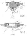
- the air outlet nozzles D according to FIGS. 2 and 3 are in the Floor or wall 12 of a bathtub can be tightened.
- Nozzle housing 13 is for this purpose with appropriate Provide external threads, so that tightening with the help an outer cover plate 14 with an internal thread and central Hole as well as with a clamping ring 15 with an internal thread can.
- the air is in via an air supply pipe 20 the housing 13 and from there via an air inlet 17 in the Body 16 out.
- the air inlet 17 is by means of a Sealing ring 18 made of rubber or the like in the conical Inlet 19 insertable and there with the help of the cover plate 14 securely clamped.
- the air passes over the Air supply pipe 20 from below into a chamber of the housing 13 a, which upwards from the plate-shaped body 16 air-permeable porous material is covered.
- the plate-shaped body 16 lies over a sealing ring 18 resilient on a shoulder of the housing 13 and can in this way with the help of the cover plate 14 be tightened. In both cases the exchange of the Body 16 possible in a simple manner, should it be defective or to be congested.
Landscapes
- Health & Medical Sciences (AREA)
- Engineering & Computer Science (AREA)
- Public Health (AREA)
- Rehabilitation Therapy (AREA)
- Animal Behavior & Ethology (AREA)
- Epidemiology (AREA)
- Pain & Pain Management (AREA)
- Physical Education & Sports Medicine (AREA)
- Mechanical Engineering (AREA)
- Life Sciences & Earth Sciences (AREA)
- General Engineering & Computer Science (AREA)
- General Health & Medical Sciences (AREA)
- Veterinary Medicine (AREA)
- Percussion Or Vibration Massage (AREA)
- Devices For Medical Bathing And Washing (AREA)
- Reciprocating Pumps (AREA)
- Gas Separation By Absorption (AREA)
Description
- Fig. 1
- schematisch eine erfindungsgemäss eingesetzte DiaphragmaLuftpumpe gemäss einem Ausführungsbeispiel,
- Fig. 2
- schematisch im Schnitt eine erfindungsgemässe Luftaustrittsdüse gemäss einer Ausgestaltung der Erfindung, und
- Fig. 3
- eine andere Ausführungsform einer erfindungsgemäss in Kombination mit einer elektromagnetisch oszillierenden Luftpumpe einzusetzenden Luftaustrittsdüse.
- 1
- elektromagnetisch oszillierende Luftpumpe (Diaphragma-Luftpumpe)
- 2
- Elektromagnet
- 3
- Permanentmagnet
- 4
- Bedienungsstange oder Schwingungselement
- 5
- Diaphragma oder Membran
- 6
- Lufteinlassöffnung
- 7
- Luftauslassöffnung
- 8
- Lufteinlassventil
- 9
- Luftauslassventil
- 10
- Zweigrohr
- 11
- Luftrohrleitung
- 12
- Boden oder Wand der Badewanne
- 13
- Düsengehäuse
- 14
- Abdeckplatte
- 15
- Klemmring
- 16
- Körper
- 17
- Lufteinlass
- 18
- Dichtring
- 19
- konisch zulaufender Stutzen
- 20
- Luftzuführungsrohr
- D
- Luftaustrittsdüsen
Claims (5)
- Sanitärwanne mit einer wenigstens eine Luftaustrittsdüse (D) aufweisenden und mit einer Luftzufuhr versehenen Luftsprudeleinrichtung, dadurch gekennzeichnet, dass für die Luftzufuhr zu der Luftaustrittsdüse (D) an diese eine elektromagnetisch oszillierende Luftpumpe (1) angeschlossen ist.
- Sanitärwanne nach Anspruch 1, dadurch gekennzeichnet, dass in dem Bereich des Übertritts des Luftstroms in das Wasser des Wanneninnenraums ein Strömungsteilungshindernis (16) vorgesehen ist.
- Sanitärwanne nach Anspruch 2, dadurch gekennzeichnet, dass das Strömungsteilungshindernis ein luftdurchlässiges mikroporöses Material ist.
- Sanitärwanne nach einem der vorhergehenden Ansprüche, dadurch gekennzeichnet, dass den Luftaustrittsdüsen (D) Wasseraustrittsdüsen zugeordnet sind.
- Sanitärwanne nach einem der vorhergehenden Ansprüche, dadurch gekennzeichnet, dass die der Luftaustrittsdüse (D) zugeführte Luft konditionierbar ist.
Applications Claiming Priority (2)
| Application Number | Priority Date | Filing Date | Title |
|---|---|---|---|
| DE19848322A DE19848322C2 (de) | 1998-10-20 | 1998-10-20 | Sanitärwanne mit Luftsprudeleinrichtung |
| DE19848322 | 1998-10-20 |
Publications (3)
| Publication Number | Publication Date |
|---|---|
| EP0995418A2 EP0995418A2 (de) | 2000-04-26 |
| EP0995418A3 EP0995418A3 (de) | 2002-03-13 |
| EP0995418B1 true EP0995418B1 (de) | 2004-10-13 |
Family
ID=7885050
Family Applications (1)
| Application Number | Title | Priority Date | Filing Date |
|---|---|---|---|
| EP99114709A Expired - Lifetime EP0995418B1 (de) | 1998-10-20 | 1999-07-28 | Sanitärwanne mit Luftsprudeleinrichtung |
Country Status (4)
| Country | Link |
|---|---|
| EP (1) | EP0995418B1 (de) |
| AT (1) | ATE279172T1 (de) |
| DE (2) | DE19848322C2 (de) |
| ES (1) | ES2229597T3 (de) |
Families Citing this family (2)
| Publication number | Priority date | Publication date | Assignee | Title |
|---|---|---|---|---|
| CN101892976B (zh) * | 2010-08-17 | 2012-07-04 | 中国工程物理研究院核物理与化学研究所 | 一种用于氚纯化的真空气体隔膜循环泵 |
| DE202010016928U1 (de) * | 2010-12-23 | 2011-08-09 | Gunther Stolz | Therapiewanne mit einer geneigten Rückenanlage-Wand |
Family Cites Families (8)
| Publication number | Priority date | Publication date | Assignee | Title |
|---|---|---|---|---|
| GB2040163A (en) * | 1979-01-24 | 1980-08-28 | Maysay Kk | Facial-washing unit |
| GB8302885D0 (en) | 1983-02-02 | 1983-03-09 | Ici Plc | Catalyst |
| DE8512416U1 (de) * | 1985-04-26 | 1986-03-06 | Schuessler, Guenter, 8000 Muenchen | Wasserbecken mit Luftsprudelvorrichtung |
| US4858255A (en) * | 1986-05-23 | 1989-08-22 | Premier Pump & Pool Products, Inc. | Hydrotherapy apparatus having preheated air agitation feature |
| JP2637135B2 (ja) * | 1988-01-26 | 1997-08-06 | マルカ精器株式会社 | 電磁ブロワー |
| EP0619110A1 (de) * | 1993-03-05 | 1994-10-12 | Ucosan B.V. | Sanitärwanne mit Luftsprudeleinrichtung |
| JPH08690A (ja) * | 1994-06-20 | 1996-01-09 | Sekisui Chem Co Ltd | 気泡発生浴槽 |
| DE19627836A1 (de) * | 1996-07-10 | 1998-01-15 | Missel Gmbh & Co E | Vorrichtung zur körperschallentkoppelten Fixierung der Ränder von Bade- und Duschwannen |
-
1998
- 1998-10-20 DE DE19848322A patent/DE19848322C2/de not_active Expired - Fee Related
-
1999
- 1999-07-28 ES ES99114709T patent/ES2229597T3/es not_active Expired - Lifetime
- 1999-07-28 DE DE1999510819 patent/DE59910819D1/de not_active Expired - Lifetime
- 1999-07-28 EP EP99114709A patent/EP0995418B1/de not_active Expired - Lifetime
- 1999-07-28 AT AT99114709T patent/ATE279172T1/de not_active IP Right Cessation
Also Published As
| Publication number | Publication date |
|---|---|
| ATE279172T1 (de) | 2004-10-15 |
| DE19848322A1 (de) | 2000-05-11 |
| EP0995418A2 (de) | 2000-04-26 |
| EP0995418A3 (de) | 2002-03-13 |
| DE59910819D1 (de) | 2004-11-18 |
| ES2229597T3 (es) | 2005-04-16 |
| DE19848322C2 (de) | 2000-12-14 |
Similar Documents
| Publication | Publication Date | Title |
|---|---|---|
| DE8631764U1 (de) | Austrittsdüse für das Austrittsventil einer Whirlpool-Wanne | |
| DE2250474C3 (de) | Unterwassermassage-Vorrichtung | |
| WO1998026810A1 (de) | Verfahren und vorrichtung zum reinstfiltern und desinfizieren vonluft | |
| DE69229187T2 (de) | Automatischer Beckenreiniger | |
| EP0209646A2 (de) | Wasserbecken mit Luftsprudelvorrichtung | |
| EP0115603A1 (de) | Hydropneumatisches Massagebad | |
| EP0290476A1 (de) | Hydro-massagedüse zur erzeugung eines luftsprudels in einem wasserbecken. | |
| DE2743530C3 (de) | Vorrichtung zum Reinigen von großflächigen TextUauflagen, insbesondere von Teppichen und Teppichboden | |
| DE3716683A1 (de) | Hydro-massageduese mit angebautem druckerzeuger | |
| DE2836708A1 (de) | Mobiles reinluftgeraet | |
| DE19848322C2 (de) | Sanitärwanne mit Luftsprudeleinrichtung | |
| AT522780B1 (de) | Vorrichtung zur reinigung von gas | |
| DE102004021470B3 (de) | Vorrichtung zur Erzeugung eines Massagestromes in einer Sanitärwanne | |
| DE69321529T2 (de) | Whirlpooldüse zur Herstellung eines Wasser/Luft-Gemisches | |
| EP0351813B1 (de) | Reinigungseinrichtung für das Rohrleitungssystem einer Whirlpool-Wanne | |
| DE68912402T2 (de) | Massage-Einheit. | |
| DE3515139A1 (de) | Wasserbecken mit luftsprudelvorrichtung | |
| EP0232532B1 (de) | Fliehkraftbearbeitungsmaschine | |
| EP0613673B2 (de) | Austrittsdüse für Badewanne zum Erzeugen eines Luft- und/oder eines Wassersprudels | |
| DE29622001U1 (de) | Vorrichtung zum Reinstfiltern und Desinfizieren von Luft | |
| DE19713381C1 (de) | Massagegerät | |
| DE3339948C2 (de) | Umwälzpumpe für Wasserstrahler an Badewannen | |
| EP0503239A1 (de) | Wanne, insbesondere Sanitärwanne, mit Luftsprudeleinrichtung | |
| DE10029415C2 (de) | Duschkopf zur Säuberung und Behandlung von Hautflächen und Körperöffnungen | |
| DE19933994A1 (de) | Zu- und Entlüftungssystem |
Legal Events
| Date | Code | Title | Description |
|---|---|---|---|
| PUAI | Public reference made under article 153(3) epc to a published international application that has entered the european phase |
Free format text: ORIGINAL CODE: 0009012 |
|
| AK | Designated contracting states |
Kind code of ref document: A2 Designated state(s): AT BE CH CY DE DK ES FI FR GB GR IE IT LI LU MC NL PT SE |
|
| AX | Request for extension of the european patent |
Free format text: AL;LT;LV;MK;RO;SI |
|
| PUAL | Search report despatched |
Free format text: ORIGINAL CODE: 0009013 |
|
| AK | Designated contracting states |
Kind code of ref document: A3 Designated state(s): AT BE CH CY DE DK ES FI FR GB GR IE IT LI LU MC NL PT SE |
|
| AX | Request for extension of the european patent |
Free format text: AL;LT;LV;MK;RO;SI |
|
| RAP1 | Party data changed (applicant data changed or rights of an application transferred) |
Owner name: VILLEROY & BOCH WELLNESS B.V. |
|
| 17P | Request for examination filed |
Effective date: 20020404 |
|
| AKX | Designation fees paid |
Free format text: AT BE CH CY DE DK ES FI FR GB GR IE IT LI LU MC NL PT SE |
|
| 17Q | First examination report despatched |
Effective date: 20030326 |
|
| GRAP | Despatch of communication of intention to grant a patent |
Free format text: ORIGINAL CODE: EPIDOSNIGR1 |
|
| GRAS | Grant fee paid |
Free format text: ORIGINAL CODE: EPIDOSNIGR3 |
|
| GRAA | (expected) grant |
Free format text: ORIGINAL CODE: 0009210 |
|
| AK | Designated contracting states |
Kind code of ref document: B1 Designated state(s): AT BE CH CY DE DK ES FI FR GB GR IE IT LI LU MC NL PT SE |
|
| PG25 | Lapsed in a contracting state [announced via postgrant information from national office to epo] |
Ref country code: IE Free format text: LAPSE BECAUSE OF FAILURE TO SUBMIT A TRANSLATION OF THE DESCRIPTION OR TO PAY THE FEE WITHIN THE PRESCRIBED TIME-LIMIT Effective date: 20041013 Ref country code: FI Free format text: LAPSE BECAUSE OF FAILURE TO SUBMIT A TRANSLATION OF THE DESCRIPTION OR TO PAY THE FEE WITHIN THE PRESCRIBED TIME-LIMIT Effective date: 20041013 |
|
| REG | Reference to a national code |
Ref country code: GB Ref legal event code: FG4D Free format text: NOT ENGLISH |
|
| REG | Reference to a national code |
Ref country code: CH Ref legal event code: EP |
|
| REG | Reference to a national code |
Ref country code: IE Ref legal event code: FG4D Free format text: GERMAN |
|
| REF | Corresponds to: |
Ref document number: 59910819 Country of ref document: DE Date of ref document: 20041118 Kind code of ref document: P |
|
| PG25 | Lapsed in a contracting state [announced via postgrant information from national office to epo] |
Ref country code: SE Free format text: LAPSE BECAUSE OF FAILURE TO SUBMIT A TRANSLATION OF THE DESCRIPTION OR TO PAY THE FEE WITHIN THE PRESCRIBED TIME-LIMIT Effective date: 20050113 Ref country code: GR Free format text: LAPSE BECAUSE OF FAILURE TO SUBMIT A TRANSLATION OF THE DESCRIPTION OR TO PAY THE FEE WITHIN THE PRESCRIBED TIME-LIMIT Effective date: 20050113 Ref country code: DK Free format text: LAPSE BECAUSE OF FAILURE TO SUBMIT A TRANSLATION OF THE DESCRIPTION OR TO PAY THE FEE WITHIN THE PRESCRIBED TIME-LIMIT Effective date: 20050113 |
|
| GBT | Gb: translation of ep patent filed (gb section 77(6)(a)/1977) |
Effective date: 20050117 |
|
| REG | Reference to a national code |
Ref country code: ES Ref legal event code: FG2A Ref document number: 2229597 Country of ref document: ES Kind code of ref document: T3 |
|
| REG | Reference to a national code |
Ref country code: IE Ref legal event code: FD4D |
|
| PG25 | Lapsed in a contracting state [announced via postgrant information from national office to epo] |
Ref country code: LU Free format text: LAPSE BECAUSE OF NON-PAYMENT OF DUE FEES Effective date: 20050728 Ref country code: CY Free format text: LAPSE BECAUSE OF FAILURE TO SUBMIT A TRANSLATION OF THE DESCRIPTION OR TO PAY THE FEE WITHIN THE PRESCRIBED TIME-LIMIT Effective date: 20050728 Ref country code: AT Free format text: LAPSE BECAUSE OF NON-PAYMENT OF DUE FEES Effective date: 20050728 |
|
| PG25 | Lapsed in a contracting state [announced via postgrant information from national office to epo] |
Ref country code: MC Free format text: LAPSE BECAUSE OF NON-PAYMENT OF DUE FEES Effective date: 20050731 Ref country code: LI Free format text: LAPSE BECAUSE OF NON-PAYMENT OF DUE FEES Effective date: 20050731 Ref country code: CH Free format text: LAPSE BECAUSE OF NON-PAYMENT OF DUE FEES Effective date: 20050731 Ref country code: BE Free format text: LAPSE BECAUSE OF NON-PAYMENT OF DUE FEES Effective date: 20050731 |
|
| ET | Fr: translation filed | ||
| PLBE | No opposition filed within time limit |
Free format text: ORIGINAL CODE: 0009261 |
|
| STAA | Information on the status of an ep patent application or granted ep patent |
Free format text: STATUS: NO OPPOSITION FILED WITHIN TIME LIMIT |
|
| 26N | No opposition filed |
Effective date: 20050714 |
|
| REG | Reference to a national code |
Ref country code: CH Ref legal event code: PL |
|
| BERE | Be: lapsed |
Owner name: *VILLEROY & BOCH WELLNESS B.V. Effective date: 20050731 |
|
| PG25 | Lapsed in a contracting state [announced via postgrant information from national office to epo] |
Ref country code: PT Free format text: LAPSE BECAUSE OF NON-PAYMENT OF DUE FEES Effective date: 20050313 |
|
| REG | Reference to a national code |
Ref country code: DE Ref legal event code: R082 Ref document number: 59910819 Country of ref document: DE Representative=s name: MEISSNER BOLTE PATENTANWAELTE RECHTSANWAELTE P, DE Ref country code: DE Ref legal event code: R082 Ref document number: 59910819 Country of ref document: DE Representative=s name: MEISSNER, BOLTE & PARTNER GBR, DE |
|
| REG | Reference to a national code |
Ref country code: FR Ref legal event code: PLFP Year of fee payment: 18 |
|
| REG | Reference to a national code |
Ref country code: FR Ref legal event code: PLFP Year of fee payment: 19 |
|
| REG | Reference to a national code |
Ref country code: FR Ref legal event code: PLFP Year of fee payment: 20 |
|
| PGFP | Annual fee paid to national office [announced via postgrant information from national office to epo] |
Ref country code: NL Payment date: 20180724 Year of fee payment: 20 Ref country code: FR Payment date: 20180726 Year of fee payment: 20 Ref country code: DE Payment date: 20180730 Year of fee payment: 20 Ref country code: IT Payment date: 20180725 Year of fee payment: 20 Ref country code: ES Payment date: 20180828 Year of fee payment: 20 |
|
| PGFP | Annual fee paid to national office [announced via postgrant information from national office to epo] |
Ref country code: GB Payment date: 20180716 Year of fee payment: 20 |
|
| REG | Reference to a national code |
Ref country code: DE Ref legal event code: R071 Ref document number: 59910819 Country of ref document: DE |
|
| REG | Reference to a national code |
Ref country code: NL Ref legal event code: MK Effective date: 20190727 |
|
| REG | Reference to a national code |
Ref country code: GB Ref legal event code: PE20 Expiry date: 20190727 |
|
| PG25 | Lapsed in a contracting state [announced via postgrant information from national office to epo] |
Ref country code: GB Free format text: LAPSE BECAUSE OF EXPIRATION OF PROTECTION Effective date: 20190727 |
|
| REG | Reference to a national code |
Ref country code: ES Ref legal event code: FD2A Effective date: 20220127 |
|
| PG25 | Lapsed in a contracting state [announced via postgrant information from national office to epo] |
Ref country code: ES Free format text: LAPSE BECAUSE OF EXPIRATION OF PROTECTION Effective date: 20190729 |