EP0995188B1 - Verfahren und vorrichtung zum messen der signal-pegel und verzögerung bei einer vielzahl von sensoren - Google Patents
Verfahren und vorrichtung zum messen der signal-pegel und verzögerung bei einer vielzahl von sensoren Download PDFInfo
- Publication number
- EP0995188B1 EP0995188B1 EP98934034A EP98934034A EP0995188B1 EP 0995188 B1 EP0995188 B1 EP 0995188B1 EP 98934034 A EP98934034 A EP 98934034A EP 98934034 A EP98934034 A EP 98934034A EP 0995188 B1 EP0995188 B1 EP 0995188B1
- Authority
- EP
- European Patent Office
- Prior art keywords
- signal
- processing device
- filter
- signal processing
- filtering characteristic
- Prior art date
- Legal status (The legal status is an assumption and is not a legal conclusion. Google has not performed a legal analysis and makes no representation as to the accuracy of the status listed.)
- Expired - Lifetime
Links
- 238000000034 method Methods 0.000 title claims description 14
- 230000003044 adaptive effect Effects 0.000 claims description 67
- 238000012545 processing Methods 0.000 claims description 35
- 238000001914 filtration Methods 0.000 claims description 34
- 239000013598 vector Substances 0.000 claims description 17
- 230000000694 effects Effects 0.000 claims description 16
- 238000004422 calculation algorithm Methods 0.000 claims description 14
- YBJHBAHKTGYVGT-ZKWXMUAHSA-N (+)-Biotin Chemical compound N1C(=O)N[C@@H]2[C@H](CCCCC(=O)O)SC[C@@H]21 YBJHBAHKTGYVGT-ZKWXMUAHSA-N 0.000 claims description 7
- FEPMHVLSLDOMQC-UHFFFAOYSA-N virginiamycin-S1 Natural products CC1OC(=O)C(C=2C=CC=CC=2)NC(=O)C2CC(=O)CCN2C(=O)C(CC=2C=CC=CC=2)N(C)C(=O)C2CCCN2C(=O)C(CC)NC(=O)C1NC(=O)C1=NC=CC=C1O FEPMHVLSLDOMQC-UHFFFAOYSA-N 0.000 claims description 7
- NCGICGYLBXGBGN-UHFFFAOYSA-N 3-morpholin-4-yl-1-oxa-3-azonia-2-azanidacyclopent-3-en-5-imine;hydrochloride Chemical compound Cl.[N-]1OC(=N)C=[N+]1N1CCOCC1 NCGICGYLBXGBGN-UHFFFAOYSA-N 0.000 claims description 4
- 239000011159 matrix material Substances 0.000 claims description 4
- 230000005540 biological transmission Effects 0.000 claims description 3
- 238000007493 shaping process Methods 0.000 claims 2
- 238000013459 approach Methods 0.000 description 10
- 230000035945 sensitivity Effects 0.000 description 9
- 230000001934 delay Effects 0.000 description 7
- 230000003111 delayed effect Effects 0.000 description 7
- 238000005259 measurement Methods 0.000 description 7
- 230000001364 causal effect Effects 0.000 description 5
- 238000013461 design Methods 0.000 description 4
- 230000002238 attenuated effect Effects 0.000 description 3
- 238000006243 chemical reaction Methods 0.000 description 3
- 238000004891 communication Methods 0.000 description 3
- 230000009977 dual effect Effects 0.000 description 3
- 238000007781 pre-processing Methods 0.000 description 3
- 238000000926 separation method Methods 0.000 description 3
- 238000004364 calculation method Methods 0.000 description 2
- 238000005070 sampling Methods 0.000 description 2
- 239000000654 additive Substances 0.000 description 1
- 230000000996 additive effect Effects 0.000 description 1
- 230000001413 cellular effect Effects 0.000 description 1
- 238000001514 detection method Methods 0.000 description 1
- 238000002592 echocardiography Methods 0.000 description 1
- 230000007613 environmental effect Effects 0.000 description 1
- 238000009434 installation Methods 0.000 description 1
- 230000010354 integration Effects 0.000 description 1
- 238000004088 simulation Methods 0.000 description 1
- 230000003595 spectral effect Effects 0.000 description 1
Images

Classifications
-
- G—PHYSICS
- G10—MUSICAL INSTRUMENTS; ACOUSTICS
- G10K—SOUND-PRODUCING DEVICES; METHODS OR DEVICES FOR PROTECTING AGAINST, OR FOR DAMPING, NOISE OR OTHER ACOUSTIC WAVES IN GENERAL; ACOUSTICS NOT OTHERWISE PROVIDED FOR
- G10K11/00—Methods or devices for transmitting, conducting or directing sound in general; Methods or devices for protecting against, or for damping, noise or other acoustic waves in general
- G10K11/16—Methods or devices for protecting against, or for damping, noise or other acoustic waves in general
- G10K11/175—Methods or devices for protecting against, or for damping, noise or other acoustic waves in general using interference effects; Masking sound
- G10K11/178—Methods or devices for protecting against, or for damping, noise or other acoustic waves in general using interference effects; Masking sound by electro-acoustically regenerating the original acoustic waves in anti-phase
-
- G—PHYSICS
- G10—MUSICAL INSTRUMENTS; ACOUSTICS
- G10K—SOUND-PRODUCING DEVICES; METHODS OR DEVICES FOR PROTECTING AGAINST, OR FOR DAMPING, NOISE OR OTHER ACOUSTIC WAVES IN GENERAL; ACOUSTICS NOT OTHERWISE PROVIDED FOR
- G10K11/00—Methods or devices for transmitting, conducting or directing sound in general; Methods or devices for protecting against, or for damping, noise or other acoustic waves in general
- G10K11/18—Methods or devices for transmitting, conducting or directing sound
- G10K11/26—Sound-focusing or directing, e.g. scanning
- G10K11/34—Sound-focusing or directing, e.g. scanning using electrical steering of transducer arrays, e.g. beam steering
- G10K11/341—Circuits therefor
- G10K11/345—Circuits therefor using energy switching from one active element to another
-
- H—ELECTRICITY
- H04—ELECTRIC COMMUNICATION TECHNIQUE
- H04M—TELEPHONIC COMMUNICATION
- H04M9/00—Arrangements for interconnection not involving centralised switching
- H04M9/08—Two-way loud-speaking telephone systems with means for conditioning the signal, e.g. for suppressing echoes for one or both directions of traffic
Definitions
- the present invention relates to signal processing, and more particularly to the measurement of signal levels and time delays at multiple signal sensors.
- dual microphones can be used in combination with beamforming methods to reduce the effects of background noise and echoes in an automobile.
- information regarding the relative sensitivities of the microphones with respect to different acoustic sources is used, for example, to form a spatial beam toward a particular user and/or to form a spatial notch against another user or a loudspeaker.
- Such an approach requires that dynamic information with respect to microphone sensitivity be quickly and accurately obtained.
- Figure 1 depicts a prior art system 100 for measuring the relative sensitivities of dual microphones with respect to different signal sources in the context of hands-free mobile telephony.
- the prior art system 100 includes a first microphone 115, a second microphone 125, an adaptive filter 135 and a summing device 140.
- An output y 1 ( k ) of the first microphone 115 is coupled to a positive input of the summing device 140, and an output y 2 ( k ) of the second microphone 125 is coupled to an input of the adaptive filter 135.
- An output ⁇ 1 ( k ) of the adaptive filter 135 is coupled to a negative input of the summing device 140, and an output e ( k ) of the summing device 140 is used as a feedback signal to the adaptive filter 135.
- the first microphone 115 is positioned nearer a first source 110
- the second microphone 125 is positioned nearer a second source 120.
- the first microphone 115 can be a hands-free microphone attached to a sun visor situated nearer a driver of an automobile
- the second microphone 125 can be a built-in microphone within a mobile unit attached nearer a passenger in the automobile.
- analog pre-processing and analog-to-digital conversion circuitry can be included at the output of each of the first and second microphones 115, 125 so that digital signals are processed by the adaptive filter 135 and the summing device 140.
- the output e ( k ) of the summing device 140 represents the difference between the output y 1 ( k ) of the first microphone 115 and the output ⁇ 1 ( k ) of the adaptive filter 135 and is referred to herein as an error signal.
- filter coefficients of the adaptive filter 135 are adjusted using a least-squares algorithm such that the error signal e ( k ) is minimized.
- the adaptive filter 135 is adjusted such that the output ⁇ 1 ( k ) of the adaptive filter 135 is as close as possible to (i.e., is an estimator of) the output y 1 ( k ) of the first microphone 115.
- the adaptive filter 135 attempts to model the signal effects created by the physical separation of the microphones 115, 125.
- the adaptive filter 135 is adjusted to provide similar delay and attenuation effects.
- the relative time delay and signal attenuation at the microphones with respect to each user can be calculated based on the coefficients of the adaptive filter 135 as described, for example, in Y.T. Chan, J.M. Riley and J.B. Plant, "A parameter estimation approach to time delay estimation and signal detection", IEEE Transactions on Acoustics, Speech and Signal Processing, vol. ASSP-28, Feb. 1980.
- US-A-4,672,674 discloses a system for noise cancellation, in which inputs from two microphones are both filtered, and the resulting filtered signals are summed. An adaptive filter in one of the input paths is adjusted to enable improved noise cancellation.
- the present invention fulfills the above-described and other needs by providing a system according to claim 1 in which a fixed filter and an adaptive filter are used in combination to provide accurate and robust estimates of signal levels and time delays for multiple sensors.
- the fixed filter includes at least one relatively narrow passband which is used to distinguish signal sources of interest from broad-band background noise.
- the fixed filter is coupled to a reference sensor and the adaptive filter is coupled to a secondary sensor.
- An error signal derived from the outputs of the fixed filter and the adaptive filter is used to adjust filter coefficients of the adaptive filter according to a suitable least-squares algorithm.
- the coefficients of the fixed filter and the adaptive filter are used to compute estimates of the time delay and relative level between the two sensors. The estimates can then be used to make decisions regarding sensor selection and beamforming.
- the functionality of the system is supplemented with an activity detector which indicates when no signal of interest is present.
- activity detector In the activity detector, accumulated energy in the adaptive filter is compared with an expected least value derived from the coefficients of the fixed filter. When the accumulated energy is smaller than the expected value, indicating that there is no signal of interest present (i.e., only background noise is present), the time delay and relative level estimates are set to appropriate values to ensure proper operation of the system even during periods where no signals of interest are present.
- more than two signal sensors are employed.
- one sensor is treated as a reference sensor and coupled to a fixed filter, while each of the additional sensors is coupled to an adaptive filter.
- an error signal derived from the outputs of the fixed filter and the corresponding adaptive filter is used to update the coefficients of the corresponding adaptive filter.
- the present invention provides a computationally simple yet accurate and robust method according to claim 23 for estimating the time delays and relative signal levels at multiple sensors.
- the teachings of the invention are applicable in a wide variety of signal processing contexts.
- the invention may be used for other acoustic applications such as teleconferencing.
- the present invention is applicable in radio communication applications where the signals of interest are radio-frequency transmissions (e.g., from mobile units and/or base stations in a cellular radio system) and the sensors are radio-frequency-sensitive antenna elements.
- Figure 2 depicts a level and delay measurement system 200 constructed in accordance with the teachings of the present invention.
- the system 200 includes a first sensor 215, a second sensor 225, a fixed FIR filter 230, an adaptive FIR filter 235 and a summing device 240.
- An output y 1 ( k ) of the first sensor 215 is coupled to an input of the fixed filter 230, and an output y F ( k ) of the fixed filter 230 is coupled to a positive input of the summing device 240.
- An output y 2 ( k ) of the second sensor 225 is coupled to an input of the adaptive filter 235 and an output ⁇ ( k ) of the adaptive filter 235 is coupled to a negative input of the summing device 240.
- An error signal e ( k ) which is output by the summing device 240 is fed back to the adaptive filter 235.
- the first sensor 215 is positioned nearer a first signal source 210
- the second sensor 225 is positioned nearer a second signal source 220.
- the first sensor 215 can be a hands-free microphone attached to a sun visor situated nearer a driver of an automobile
- the second sensor 225 can be a built-in microphone within a mobile unit attached nearer a passenger in the automobile.
- the first and second sensors 215, 225 can be antenna elements positioned nearer first and second radio-frequency signal sources, respectively.
- analog pre-processing and analog-to-digital conversion circuitry can be included at the output of each of the first and second sensors 215, 225 so that digital signals are processed by the fixed filter 230, the adaptive filter 235 and the summing device 240.
- the fixed filter 230 is designed to include at least one relatively narrow pass-band of interest.
- a pass-band can correspond to the 300-600 Hz frequency band in which most of the energy of human speech is concentrated.
- a pass-band can correspond to a bandwidth allocated for radio-frequency transmissions.
- the coefficients of the fixed filter 230 can be adjusted as necessary to compensate for changes in application requirements or environmental conditions.
- the fixed filter 230 can be set to optimize received signal-to-noise ratio for a particular automobile installation.
- the coefficients of the filter 230 can be adjusted dynamically, for example in dependence upon measured signal-to-noise ratio.
- the fixed filter 230 is designed to provide unity gain and zero phase in each passband. Additionally, the noise gain of the fixed filter 230 is minimized in order to ensure maximal stop-band attenuation. As described in more detail below, the prior information provided by the fixed filter 230 (i.e., the narrowband nature of the signals output by the fixed filter 230) is used to make the system robust against background noise.
- filter coefficients of the adaptive filter 235 are adjusted using a suitable least-squares algorithm such that the error signal e ( k ) is minimized and such that the output ⁇ ( k ) of the adaptive filter 235 is as close as possible to the output y F ( k ) of the fixed filter 230.
- the relative time delay and signal attenuation at the first and second sensors 215, 225 with respect to each source 210, 220 are calculated based on the coefficients of the adaptive filter 235 and the prior information associated with the fixed filter 230.
- an appropriate digital signal processor can be integrated with the system 200 to perform the least-squares update of the adaptive filter 235 and to compute the time delay and signal level estimates.
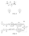
- Figure 3 depicts a typical example of source and sensor placement in two dimensions.
- first and second sensors 215, 225 are positioned adjacent two signal sources 210, 220.
- a signal emanating from the first signal source 210 (as indicated by a first dashed arc 315) will impinge upon the first signal sensor 215 before impinging upon the second signal sensor 225.
- the signal received at the second sensor 225 due to the first signal source 210 will be a delayed and attenuated version of the signal received at the first sensor 215 due to the same source 210.
- a signal emanating from the second source 220 (as indicated by a second dashed arc 325) will impinge upon the second sensor 225 before impinging upon the first sensor 215, and the signal received at the first sensor 215 due to the second signal source 220 will be a delayed and attenuated version of the signal received at the second sensor 225 due to the same source 220.
- the spacial separation (and thus the corresponding time delay and level attenuation) of the sensors 215, 225 with respect to the first and second signal sources 210, 220 are indicated in Figure 3 by second and first line segments 320, 310, respectively.
- the second sensor input x 2 ( k ) is generally a delayed and scaled version of the first sensor input x 1 ( k ).
- x 2 ( k ) 1/ S ⁇ x 1 ( k - D ), where the scale factor S is greater than zero and where the delay D may take positive as well as negative values.
- the first input x 1 ( k ) is a delayed and scaled version of the second input x 2 ( k ).
- the second input x 2 ( k ) is denoted the delayed signal for all values of D without loss of generality.
- D is defined to be ⁇ - D . Note that, for causal filtering, ⁇ > D .
- Figure 4 illustrates the input signals x 1 ( k ), x 2 ( k ) and the intermediate signals y 1 ( k ), y 2 ( k ) in the context of a level and delay measurement system.
- the system 400 of Figure 4 is identical to the system 200 of Figure 2 except that a delay block 410 (corresponding to the fixed delay ⁇ described above) is positioned between the first sensor 215 and the fixed filter 230.
- a delay block 410 corresponding to the fixed delay ⁇ described above
- the present invention provides a computationally simple yet accurate method for estimating the delay D and the scale factor S based on the measured sensor inputs x 1 ( k ) and x 2 ( k ).
- the method is robust against background noise so that it may be used successfully, for example, in the above described hands-free mobile telephony context.
- the estimated quantities say D k and S k (where k indicates that sensor inputs up to and including time instant k are used for the calculation of D and S ), can be used to improve system performance.
- the estimates D k and ⁇ k can be used in combination with well known beamforming techniques to electronically enhance and reduce the sensitivity of the sensors 215, 225 with respect to the first and second sources 210, 220.
- a beam may be formed in the direction of that source to optimize its reception.
- spatial filtering can be employed to diminish the sensitivity of the sensors with respect to that source.
- the system can selectively transmit only the signal detected at a particular sensor when a particular source is active. For example, if one sensor is much more sensitive to the passenger than to the driver (e.g., due to a close physical proximity to the passenger), then it may be desirable to transmit only the signal received at that sensor when only the passenger is speaking.
- ⁇ is a gain factor (constant or time-varying) in the interval 0 ⁇ ⁇ ⁇ 2
- ⁇ 2 denotes the squared Euclidian vector norm.
- the adaptive algorithm described by equations (9) and (10) is the well known Normalized Least Mean Squares (N-LMS) algorithm.
- the coefficients of the adaptive filter 235 converge toward a delayed and scaled version of the coefficients of the fixed filter 230.
- the present invention teaches that by incorporating prior knowledge which distinguishes the source signals from background noise, system performance can be significantly improved. To ensure improved overall performance, the priors should be true in all situations. For example, the present invention teaches that such prior information is available when the energy in the source signals of interest is concentrated around one or more center frequencies, while the background noise has a relatively flat and broadband frequency content, or power spectral density. In such a context, the present invention teaches that the fixed FIR filter 230 can be designed as a band-pass filter having one or several pass bands.
- the fixed filter 230 can be designed to include two pass-bands, the first and second passbands having center frequencies of 100Hz and 250Hz, respectively.
- the fixed filter 230 can be designed to include a single pass-band having a center frequency of 200Hz and spanning a frequency band which includes the fundamental frequency of female speakers as well as the first harmonic frequency of male speakers.
- the former approach requires the use of higher order filters as compared to the latter approach.
- the order L of the filter is doubled as well.
- NG filter noise gain
- the adaptive algorithm used to update the adaptive filter 235 will cause the adaptive filter 235 to converge toward a delayed and scaled replica of the fixed filter 230.
- the coefficients of the adaptive filter 235 will converge as follows: c ⁇ k - S ⁇ c - D where S and D are the scale factor and time delay, respectively, caused by the physical separation of the sensors 215, 225.
- S and D are the scale factor and time delay, respectively, caused by the physical separation of the sensors 215, 225.
- the estimate D k can be computed iteratively in practice. Note that the delay gradient d p ( D )/ dD follows readily from equation (19).
- the present invention teaches that estimates of the scale factor S and the time delay D can be computed in a straightforward fashion.
- each of the above described computations can be carried out using well known digital signal processing components. Due to the consistent prior information provided by the fixed filter 230, the estimates will be valid even in the presence of background noise.
- the system can be further enhanced by the addition of an activity detector which ensures proper system performance even when all signal sources are inactive.
- an activity detector which ensures proper system performance even when all signal sources are inactive.
- the signals x 1 ( k ) and x 2 ( k ) received at the sensors 215, 225 will comprise uncorrelated noise only.
- the adaptive filter coefficients ⁇ ( k ) will converge toward the null vector, meaning that the scale factor estimate ⁇ k will tend toward zero while the time delay estimate D k may take any value.
- the estimates ⁇ k , D k can be explicitly set to appropriate values when an activity detector senses the absence of signals of interest.
- An exemplary activity detector compares an estimate of the filter noise gain to a predetermined threshold (i.e., an expected noise gain value).
- a predetermined threshold i.e., an expected noise gain value.
- An exemplary system can be implemented using the following pseudocode. Those skilled in the art will appreciate that such pseudocode is readily adapted for implementation using standard digital signal processing components.
- Scale Factor and Time Delay Estimation Routine Filtering compute output from the fixed FIR filter and the adaptive FIR filter (k denotes the running time index).
- Y ⁇ 1 y ⁇ 1 ⁇ k : - 1 : k - L ;
- Y ⁇ 2 y ⁇ 2 ⁇ k : - 1 : k - L ;
- Energy calculations and gain control A simple gain control scheme is used in order to set the gain ⁇ to zero if there is low energy in the inputs.
- an acoustic scenario is considered in which the sensors are presumed to be microphones and the sources are presumed to be human speakers or loudspeakers transmitting human speech.
- a scenario can arise in the context of hands-free mobile telephony used in an automobile environment.
- the example is restricted to two sensors and two sources, those skilled in the art will appreciate that the approach can be applied using an arbitrary number of sources and sensors.
- a rather severe background noise is typically present (e.g., from an AC-fan, the car engine, the road, the wind etc.).
- the sensitivities of the microphones in different directions are assumed to be as shown in Table 1. TABLE 1 - MICROPHONE SENSITIVITY TO DIFFUSE BACKGROUND NOISE AND SIGNAL SOURCES IN DIFFERENT POSITIONS.
- Signal Source First Sensor 215 e.g., sun-visor microphone
- Second Sensor 225 e.g., built-in microphone
- Second Source 220 -10dB 0dB e.g., passenger
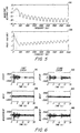
- Additive background noise was modeled as white Gaussian noise.
- the noise signals detected at the first and second sensors 215, 225 are depicted in third and fourth plots 630, 620, respectively, of Figure 6.
- the combined speech and noise signals measured at the first and second sensors 215, 225 are depicted in fifth and sixth plots 650, 660, respectively of Figure 6.
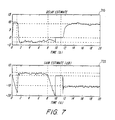
- the results are shown in Figure 7.
- the delay estimate D k is depicted in a first plot 710
- the scale factor estimate S k is depicted in a second plot 720.
- every 50-th sample is displayed.
- Horizontal dashed lines indicate delays of -3, 0, and 9 samples as well as gains of -10dB, 0dB, and 3dB.
- the system properly provides scale factor and time delay estimates, respectively, of 0db and approximately -3 samples when the driver is speaking and -10db and approximately 9 samples when the passenger is speaking.
- the activity detector properly sets the scale factor and time delay estimates, respectively, to 0db and 0 samples during the period when both the driver and the passenger are silent.
- the adaptive scheme comprises an adaptive block that can serve as a signal smoother, a backward predictor ( D ⁇ 0) and/or a forward predictor ( D > 0).
- D ⁇ 0
- D > 0 a forward predictor
- ⁇ can be set based upon system design considerations. For example, ⁇ can be set to cover "most situations” and not “all possible situations” since the system will provide reasonable results even in rare extreme situations.
Landscapes
- Engineering & Computer Science (AREA)
- Acoustics & Sound (AREA)
- Multimedia (AREA)
- Physics & Mathematics (AREA)
- Signal Processing (AREA)
- Circuit For Audible Band Transducer (AREA)
- Soundproofing, Sound Blocking, And Sound Damping (AREA)
- Interconnected Communication Systems, Intercoms, And Interphones (AREA)
- Noise Elimination (AREA)
- Indication And Recording Devices For Special Purposes And Tariff Metering Devices (AREA)
- Measurement Of Mechanical Vibrations Or Ultrasonic Waves (AREA)
- Testing Or Calibration Of Command Recording Devices (AREA)
- Radar Systems Or Details Thereof (AREA)
Claims (28)
- Signalverarbeitungsvorrichtung, welche enthält:einen ersten Signalsensor (215);einen zweiten Signalsensor (225);einen adaptiven Filter (235), welcher einen an einem Ausgang des zweiten Sensors gekoppelten Eingang hat und eine einstellbare Filtercharakteristik hat;eine Summiervorrichtung (240), wobei die einstellbare Filtercharakteristik des adaptiven Filters (235) in Abhängigkeit von einer Ausgabe der Summiervorrichtung (240) eingestellt ist; undeinen Prozessor;einen Bandpassfilter (230), welcher einen an einem Ausgang des ersten Sensors gekoppelten Eingang hat, wobei der Bandpassfilter einen Durchlassbereich hat, welcher einem Frequenzband entspricht, welches ein Signal von Interesse enthält;wobei die Summiervorrichtung (240) einen an einem Ausgang des Bandpassfilters (230) gekoppelten ersten Eingang und einen an einem Ausgang des adaptiven Filters (235) gekoppelten zweiten Eingang hat;
ein Mittel zum Einstellen der Filtercharakteristik des adaptiven Filters, so dass eine Ausgabe des adaptiven Filters so nah wie möglich an einer Ausgabe des Bandpassfilters ist; und
dadurch gekennzeichnet, dass der Prozessor dazu angepasst ist, Abschätzungen von einer relativen Zeitverzögerung und einem relativen Skalierungsfaktor zwischen dem ersten und zweiten Sensor mit Bezug auf eine Signalquelle in Abhängigkeit von einer Filtercharakteristik des Bandpassfilters und der einstellbaren Filtercharakteristik des adaptiven Filters zu berechnen. - Signalverarbeitungsvorrichtung nach Anspruch 1, bei welcher der Bandpassfilter, der adaptive Filter, die Summiervorrichtung und der Prozessor unter Verwendung einer digitalen Signalprozessor (DSP)-Integrationsschaltung (IC) implementiert sind.
- Signalverarbeitungsvorrichtung nach Anspruch 1, bei welcher der Bandpassfilter, der adaptive Filter, die Summiervorrichtung und der Prozessor unter Verwendung einer applikationsspezifischen Integrationsschaltung (ASIC) implementiert sind.
- Signalverarbeitungsvorrichtung nach Anspruch 1, bei welcher die Signalverarbeitungsvorrichtung ein Telefon ist, und bei welcher der erste und zweite Sensor Mikrofone sind.
- Signalverarbeitungsvorrichtung nach Anspruch 1, bei welcher die Signalverarbeitungsvorrichtung ein Funk-Transceiver ist, und bei welcher der erste und zweite Sensor Antennenelemente sind.
- Signalverarbeitungsvorrichtung nach Anspruch 1, bei welcher der Bandpassfilter ein Filter mit begrenztem Impulsansprechverhalten (FIR) ist, welcher eine festgelegte Filtercharakteristik hat.
- Signalverarbeitungsvorrichtung nach Anspruch 1, bei welcher die Filtercharakteristik des Bandpassfilters zumindest einen Durchlassbereich enthält, welcher einen Einheits-Verstärkungsfaktor und eine Null-Phasen-Verzögerung bei einer Mittenfrequenz des Durchlassbereichs bereitstellt.
- Signalverarbeitungsvorrichtung nach Anspruch 1, bei welcher die Filtercharakteristik des Bandpassfilters Koeffizienten enthält, welche derart eingestellt sind, um eine Rauschverstärkung des Bandpassfilters zu minimieren.
- Signalverarbeitungsvorrichtung nach Anspruch 1, bei welcher die Filtercharakteristik des Bandpassfilters Koeffizienten enthält, welche derart eingestellt sind, um ein Signal-zu-Rauschen-Verhältnis des Bandpassfilters zu optimieren.
- Signalverarbeitungsvorrichtung nach Anspruch 1, bei welcher die einstellbare Filtercharakteristik des adaptiven Filters unter Verwendung eines Normalized Least Mean Squares (NLMS)-Algorithmus eingestellt ist.
- Signalverarbeitungsvorrichtung nach Anspruch 1, bei welcher die einstellbare Filtercharakteristik des adaptiven Filters unter Verwendung eines Least Mean Squares (LMS)-Algorithmus eingestellt ist.
- Signalverarbeitungsvorrichtung nach Anspruch 1, bei welcher die einstellbare Filtercharakteristik des adaptiven Filters unter Verwendung eines Recursive Least Squares (RLS)-Algorithmus eingestellt ist.
- Signalverarbeitungsvorrichtung nach Anspruch 1, welche ferner einen Strahlformer zum Formen eines durch den ersten und zweiten Sensor bereitgestellten Strahlmusters in Abhängigkeit von den Abschätzungen der relativen Zeitverzögerung und des relativen Skalierungsfaktors zwischen dem ersten und zweiten Sensor enthält.
- Signalverarbeitungsvorrichtung nach Anspruch 13, bei welcher das Strahlmuster einen räumlichen Strahl enthält, welcher in Richtung auf eine bestimmte Signalquelle gezielt ist.
- Signalverarbeitungsvorrichtung nach Anspruch 13, bei welcher das Strahlmuster eine räumliche Kerbe enthält, welche auf eine bestimmte Signalquelle gezielt ist.
- Signalverarbeitungsvorrichtung nach Anspruch 1, bei welcher der Prozessor ein durch einen bestimmten aus dem ersten und zweiten Sensor erfasstes Signal zur Übertragung in Abhängigkeit von den Abschätzungen der relativen Zeitverzögerung und dem relativen Skalierungsfaktor zwischen dem ersten und zweiten Sensor auswählt.
- Signalverarbeitungsvorrichtung nach Anspruch 1, welche ferner zumindest einen zusätzlichen Sensor und zumindest einen zusätzlichen Filter, welcher eine einstellbare Filtercharakteristik hat, enthält,
wobei die einstellbare Filtercharakteristik des zusätzlichen Filters in Abhängigkeit von einer Differenz zwischen der Ausgabe des Bandpassfilters und einer Ausgabe des zusätzlichen Filters eingestellt ist, und
wobei der Prozessor eine Abschätzung von zumindest einem Parameter bezüglich des ersten Sensors und des zusätzlichen Sensors in Abhängigkeit von der Filtercharakteristik des Bandpassfilters und der einstellbaren Filtercharakteristik des zusätzlichen Filters berechnet. - Signalverarbeitungsvorrichtung nach Anspruch 17, bei welcher der Prozessor Abschätzungen von einer relativen Zeitverzögerung und einen relativen Skalierungsfaktor zwischen dem ersten Sensor und dem zusätzlichen Sensor mit Bezug auf eine Signalquelle berechnet.
- Signalverarbeitungsvorrichtung nach Anspruch 1, welche ferner einen Aktivitätserfasser enthält, um zu erfassen, wann eine Signalquelle von Interesse aktiv ist, wobei der Prozessor die Abschätzungen der relativen Zeitverzögerung und den relativen Skalierungsfaktor auf vorbestimmte Werte einstellt, wenn der Aktivitätserfasser anzeigt, dass keine Signalquelle von Interesse aktiv ist.
- Signalverarbeitungsvorrichtung nach Anspruch 19, bei welcher der Prozessor die Abschätzung der relativen Zeitverzögerung auf Null und die Abschätzung des Skalierungsfaktors auf Eins einstellt, wenn der Aktivitätserfasser anzeigt, dass keine Signalquelle von Interesse aktiv ist.
- Signalverarbeitungsvorrichtung nach Anspruch 1, welche ferner einen Festgelegte-Verzögerung-Block enthält, welcher sich in einem Signalflusspfad entsprechend des ersten Sensors befindet.
- Signalverarbeitungsvorrichtung nach Anspruch 1,
bei welcher Filtercharakteristiken des Bandpassfilters und des adaptiven Filters jeweils eine Anzahl L von Filterkoeffizienten enthalten,
wobei die Filtercharakteristik des Bandpassfilters eine Anzahl m von Durchlassbereichen enthält, wobei jeder Durchlassbereich 1, 1 ∈ (1, m) eine Mittenfrequenz ω1 hat, und
bei welcher eine Abschätzung Dk von einer relativen Zeitverzögerung D zwischen dem ersten und zweiten Sensor und eine Abschätzung Ŝk von einem relativen Skalierungsfaktor S zwischen dem ersten und zweiten Sensor zu einem Zeitpunkt k basierend auf der einstellbaren Filtercharakteristik ĉ(k) des adaptiven Filters, einer Matrix L und einem Prädiktions-Vektor p(D) berechnet werden zu:

wobei die Matrix L und der Prädiktions-Vektor p(D) berechnet werden zu:

- Verfahren zur Signalverarbeitung, welches die Schritte enthält:Erfassen eines ersten Signals unter Verwendung eines ersten Signalsensors;Erfassen eines zweiten Signals unter Verwendung eines zweiten Signalsensors;Filtern des zweiten Signals unter Verwendung eines adaptiven Filters, welcher eine einstellbare Filtercharakteristik hat, um ein gefiltertes zweites Signal bereitzustellen;Filtern des ersten Signals untere Verwendung eines Bandpassfilters, welcher einen Durchlassbereich hat, welcher einem Frequenzband entspricht, welches ein Signal von Interesse enthält, um ein gefiltertes erstes Signal bereitzustellen;Berechnen einer Differenz zwischen dem gefilterten ersten Signal und dem gefilterten zweiten Signal;Einstellen der Filtercharakteristik des adaptiven Filters derart, dass die Differenz minimiert wird; undgekennzeichnet durch
Berechnen von Abschätzungen von einer relativen Zeitverzögerung und einem relativen Skalierungsfaktor zwischen dem ersten und zweiten Sensor mit Bezug auf eine Signalquelle in Abhängigkeit von einer Filtercharakteristik des Bandpassfilters und der einstellbaren Filtercharakteristik des adaptiven Filters. - Verfahren nach Anspruch 23, bei welchem die Filtercharakteristik des Bandpassfilters zumindest einen Durchlassbereich enthält, welcher einen Einheits-Verstärkungsfaktor und eine Null-Phasen-Verzögerung bei einer Mittenfrequenz des Durchlassbereichs bereitstellt.
- Verfahren nach Anspruch 23, bei welchem die Filtercharakteristik des adaptiven Filters unter Verwendung eines Normalized Least Mean Squares (NLMS)-Algorithmus eingestellt wird.
- Verfahren nach Anspruch 23, welches ferner einen Schritt eines Formens eines Strahlmusters, welches durch den ersten und zweiten Sensor bereitgestellt wird, in Abhängigkeit von der relativen Zeitverzögerung und dem relativen Skalierungsfaktor enthält, welche resultierend aus dem Schritt des Abschätzens erlangt werden.
- Verfahren nach Anspruch 23, welches ferner einen Schritt eines Auswählens und Übertragens von einem Signal enthält, welches durch einen bestimmten aus dem ersten und zweiten Sensor in Abhängigkeit von der relativen Zeitverzögerung und dem relativen Skalierungsfaktor erfasst wird, welche resultierend aus dem Schritt des Abschätzens erlangt werden.
- Verfahren nach Anspruch 23, welches ferner die Schritte eines Erfassens, ob eine Signalquelle von Interesse aktiv ist, und Einstellens von einer relativen Zeitverzögerungs- und Skalierungsfaktor-Abschätzung auf vorbestimmte Werte enthält, wenn der Schritt des Erfassens anzeigt, dass keine Quelle von Interesse aktiv ist.
Applications Claiming Priority (3)
| Application Number | Priority Date | Filing Date | Title |
|---|---|---|---|
| US890768 | 1997-07-11 | ||
| US08/890,768 US6430295B1 (en) | 1997-07-11 | 1997-07-11 | Methods and apparatus for measuring signal level and delay at multiple sensors |
| PCT/SE1998/001319 WO1999003091A1 (en) | 1997-07-11 | 1998-07-03 | Methods and apparatus for measuring signal level and delay at multiple sensors |
Publications (2)
| Publication Number | Publication Date |
|---|---|
| EP0995188A1 EP0995188A1 (de) | 2000-04-26 |
| EP0995188B1 true EP0995188B1 (de) | 2007-04-25 |
Family
ID=25397124
Family Applications (1)
| Application Number | Title | Priority Date | Filing Date |
|---|---|---|---|
| EP98934034A Expired - Lifetime EP0995188B1 (de) | 1997-07-11 | 1998-07-03 | Verfahren und vorrichtung zum messen der signal-pegel und verzögerung bei einer vielzahl von sensoren |
Country Status (15)
| Country | Link |
|---|---|
| US (1) | US6430295B1 (de) |
| EP (1) | EP0995188B1 (de) |
| JP (1) | JP4082649B2 (de) |
| KR (1) | KR100480404B1 (de) |
| CN (1) | CN1122963C (de) |
| AU (1) | AU747618B2 (de) |
| BR (1) | BR9810695A (de) |
| DE (1) | DE69837663D1 (de) |
| EE (1) | EE200000008A (de) |
| HK (1) | HK1031421A1 (de) |
| MY (1) | MY120049A (de) |
| PL (1) | PL337971A1 (de) |
| SG (1) | SG70644A1 (de) |
| TW (1) | TW386330B (de) |
| WO (1) | WO1999003091A1 (de) |
Families Citing this family (65)
| Publication number | Priority date | Publication date | Assignee | Title |
|---|---|---|---|---|
| US7146013B1 (en) * | 1999-04-28 | 2006-12-05 | Alpine Electronics, Inc. | Microphone system |
| US20010028718A1 (en) | 2000-02-17 | 2001-10-11 | Audia Technology, Inc. | Null adaptation in multi-microphone directional system |
| US7155019B2 (en) | 2000-03-14 | 2006-12-26 | Apherma Corporation | Adaptive microphone matching in multi-microphone directional system |
| JP2003528508A (ja) * | 2000-03-20 | 2003-09-24 | オーディア テクノロジー インク | 多重マイクロフォン・システムのための方向処理 |
| US6861946B2 (en) * | 2000-05-17 | 2005-03-01 | Caveo Technology Llc. | Motion-based input system for handheld devices |
| US20030179888A1 (en) * | 2002-03-05 | 2003-09-25 | Burnett Gregory C. | Voice activity detection (VAD) devices and methods for use with noise suppression systems |
| US8280072B2 (en) | 2003-03-27 | 2012-10-02 | Aliphcom, Inc. | Microphone array with rear venting |
| US7246058B2 (en) * | 2001-05-30 | 2007-07-17 | Aliph, Inc. | Detecting voiced and unvoiced speech using both acoustic and nonacoustic sensors |
| US20070233479A1 (en) * | 2002-05-30 | 2007-10-04 | Burnett Gregory C | Detecting voiced and unvoiced speech using both acoustic and nonacoustic sensors |
| US8019091B2 (en) * | 2000-07-19 | 2011-09-13 | Aliphcom, Inc. | Voice activity detector (VAD) -based multiple-microphone acoustic noise suppression |
| US20020099541A1 (en) * | 2000-11-21 | 2002-07-25 | Burnett Gregory C. | Method and apparatus for voiced speech excitation function determination and non-acoustic assisted feature extraction |
| KR100394840B1 (ko) * | 2000-11-30 | 2003-08-19 | 한국과학기술원 | 독립 성분 분석을 이용한 능동 잡음 제거방법 |
| US7206418B2 (en) * | 2001-02-12 | 2007-04-17 | Fortemedia, Inc. | Noise suppression for a wireless communication device |
| US7433484B2 (en) | 2003-01-30 | 2008-10-07 | Aliphcom, Inc. | Acoustic vibration sensor |
| US20030128848A1 (en) * | 2001-07-12 | 2003-07-10 | Burnett Gregory C. | Method and apparatus for removing noise from electronic signals |
| JP2005529379A (ja) * | 2001-11-21 | 2005-09-29 | アリフコム | 電子的信号からノイズを除去する方法および装置 |
| JP2003241767A (ja) * | 2002-02-14 | 2003-08-29 | Alpine Electronics Inc | ノイズキャンセル装置 |
| US6978010B1 (en) * | 2002-03-21 | 2005-12-20 | Bellsouth Intellectual Property Corp. | Ambient noise cancellation for voice communication device |
| CN1643571A (zh) * | 2002-03-27 | 2005-07-20 | 艾黎弗公司 | 用于与通信系统一起使用的麦克风和声音活动检测(vad)配置 |
| ES2341327T3 (es) * | 2002-04-10 | 2010-06-18 | Koninklijke Philips Electronics N.V. | Codificacion y decodificacion de señales audio multicanal. |
| CN100508026C (zh) * | 2002-04-10 | 2009-07-01 | 皇家飞利浦电子股份有限公司 | 立体声信号编码 |
| US9066186B2 (en) | 2003-01-30 | 2015-06-23 | Aliphcom | Light-based detection for acoustic applications |
| US9099094B2 (en) | 2003-03-27 | 2015-08-04 | Aliphcom | Microphone array with rear venting |
| US7330556B2 (en) * | 2003-04-03 | 2008-02-12 | Gn Resound A/S | Binaural signal enhancement system |
| US8509703B2 (en) * | 2004-12-22 | 2013-08-13 | Broadcom Corporation | Wireless telephone with multiple microphones and multiple description transmission |
| US8345890B2 (en) * | 2006-01-05 | 2013-01-01 | Audience, Inc. | System and method for utilizing inter-microphone level differences for speech enhancement |
| US8744844B2 (en) | 2007-07-06 | 2014-06-03 | Audience, Inc. | System and method for adaptive intelligent noise suppression |
| US8194880B2 (en) * | 2006-01-30 | 2012-06-05 | Audience, Inc. | System and method for utilizing omni-directional microphones for speech enhancement |
| US8204252B1 (en) | 2006-10-10 | 2012-06-19 | Audience, Inc. | System and method for providing close microphone adaptive array processing |
| US9185487B2 (en) | 2006-01-30 | 2015-11-10 | Audience, Inc. | System and method for providing noise suppression utilizing null processing noise subtraction |
| US8934641B2 (en) | 2006-05-25 | 2015-01-13 | Audience, Inc. | Systems and methods for reconstructing decomposed audio signals |
| US8204253B1 (en) | 2008-06-30 | 2012-06-19 | Audience, Inc. | Self calibration of audio device |
| US8949120B1 (en) | 2006-05-25 | 2015-02-03 | Audience, Inc. | Adaptive noise cancelation |
| US8150065B2 (en) * | 2006-05-25 | 2012-04-03 | Audience, Inc. | System and method for processing an audio signal |
| US8849231B1 (en) | 2007-08-08 | 2014-09-30 | Audience, Inc. | System and method for adaptive power control |
| US8259926B1 (en) | 2007-02-23 | 2012-09-04 | Audience, Inc. | System and method for 2-channel and 3-channel acoustic echo cancellation |
| US8189766B1 (en) | 2007-07-26 | 2012-05-29 | Audience, Inc. | System and method for blind subband acoustic echo cancellation postfiltering |
| WO2009076523A1 (en) * | 2007-12-11 | 2009-06-18 | Andrea Electronics Corporation | Adaptive filtering in a sensor array system |
| US8150054B2 (en) * | 2007-12-11 | 2012-04-03 | Andrea Electronics Corporation | Adaptive filter in a sensor array system |
| US9392360B2 (en) | 2007-12-11 | 2016-07-12 | Andrea Electronics Corporation | Steerable sensor array system with video input |
| US8180064B1 (en) | 2007-12-21 | 2012-05-15 | Audience, Inc. | System and method for providing voice equalization |
| US8143620B1 (en) | 2007-12-21 | 2012-03-27 | Audience, Inc. | System and method for adaptive classification of audio sources |
| US8194882B2 (en) | 2008-02-29 | 2012-06-05 | Audience, Inc. | System and method for providing single microphone noise suppression fallback |
| US8355511B2 (en) | 2008-03-18 | 2013-01-15 | Audience, Inc. | System and method for envelope-based acoustic echo cancellation |
| US8542843B2 (en) * | 2008-04-25 | 2013-09-24 | Andrea Electronics Corporation | Headset with integrated stereo array microphone |
| US8818000B2 (en) | 2008-04-25 | 2014-08-26 | Andrea Electronics Corporation | System, device, and method utilizing an integrated stereo array microphone |
| US8774423B1 (en) | 2008-06-30 | 2014-07-08 | Audience, Inc. | System and method for controlling adaptivity of signal modification using a phantom coefficient |
| US8521530B1 (en) | 2008-06-30 | 2013-08-27 | Audience, Inc. | System and method for enhancing a monaural audio signal |
| US9008329B1 (en) | 2010-01-26 | 2015-04-14 | Audience, Inc. | Noise reduction using multi-feature cluster tracker |
| US8798290B1 (en) | 2010-04-21 | 2014-08-05 | Audience, Inc. | Systems and methods for adaptive signal equalization |
| WO2012046582A1 (ja) * | 2010-10-08 | 2012-04-12 | 日本電気株式会社 | 信号処理装置、信号処理方法、及び信号処理プログラム |
| EP2663230B1 (de) * | 2011-01-12 | 2015-03-18 | Koninklijke Philips N.V. | Verbesserte detektion von atemzyklen im schlafzimmer |
| US9640194B1 (en) | 2012-10-04 | 2017-05-02 | Knowles Electronics, Llc | Noise suppression for speech processing based on machine-learning mask estimation |
| CA2892979A1 (en) * | 2012-12-18 | 2014-06-26 | Gambro Lundia Ab | Detecting pressure pulses in a blood processing apparatus |
| US9357080B2 (en) * | 2013-06-04 | 2016-05-31 | Broadcom Corporation | Spatial quiescence protection for multi-channel acoustic echo cancellation |
| US9536540B2 (en) | 2013-07-19 | 2017-01-03 | Knowles Electronics, Llc | Speech signal separation and synthesis based on auditory scene analysis and speech modeling |
| CN104656494A (zh) * | 2013-11-19 | 2015-05-27 | 北大方正集团有限公司 | 一种信号实时性处理装置 |
| US9799330B2 (en) | 2014-08-28 | 2017-10-24 | Knowles Electronics, Llc | Multi-sourced noise suppression |
| US9685730B2 (en) | 2014-09-12 | 2017-06-20 | Steelcase Inc. | Floor power distribution system |
| US9584910B2 (en) | 2014-12-17 | 2017-02-28 | Steelcase Inc. | Sound gathering system |
| WO2018051538A1 (ja) * | 2016-09-15 | 2018-03-22 | アルプス電気株式会社 | 物理量測定装置 |
| AU2017353987B2 (en) | 2016-11-04 | 2019-10-10 | Med-El Elektromedizinische Geraete Gmbh | Bilateral synchronized channel selection for cochlear implants |
| KR102351071B1 (ko) * | 2019-11-25 | 2022-01-14 | 한국전자기술연구원 | 섬유 스트레인 센서를 포함하는 센서 모듈 |
| US11223891B2 (en) * | 2020-02-19 | 2022-01-11 | xMEMS Labs, Inc. | System and method thereof |
| CN116232282B (zh) * | 2023-01-12 | 2023-12-19 | 湖南大学无锡智能控制研究院 | 一种基于自适应全通滤波器的时变时延估计方法、装置和系统 |
Citations (1)
| Publication number | Priority date | Publication date | Assignee | Title |
|---|---|---|---|---|
| US4672674A (en) * | 1982-01-27 | 1987-06-09 | Clough Patrick V F | Communications systems |
Family Cites Families (15)
| Publication number | Priority date | Publication date | Assignee | Title |
|---|---|---|---|---|
| US3794766A (en) * | 1973-02-08 | 1974-02-26 | Bell Telephone Labor Inc | Delay equalizing circuit for an audio system using multiple microphones |
| US4631749A (en) * | 1984-06-22 | 1986-12-23 | Heath Company | ROM compensated microphone |
| JPH042928A (ja) | 1990-04-19 | 1992-01-07 | Matsushita Electric Ind Co Ltd | 音場制御装置 |
| JP2792311B2 (ja) | 1992-01-31 | 1998-09-03 | 日本電気株式会社 | 多チャンネルエコー除去方法および装置 |
| JP2508574B2 (ja) | 1992-11-10 | 1996-06-19 | 日本電気株式会社 | 多チャンネルエコ―除去装置 |
| US5400409A (en) * | 1992-12-23 | 1995-03-21 | Daimler-Benz Ag | Noise-reduction method for noise-affected voice channels |
| US5590241A (en) | 1993-04-30 | 1996-12-31 | Motorola Inc. | Speech processing system and method for enhancing a speech signal in a noisy environment |
| JPH084243B2 (ja) | 1993-05-31 | 1996-01-17 | 日本電気株式会社 | 多チャンネルエコー除去方法および装置 |
| DE69431584T2 (de) | 1993-08-12 | 2003-03-06 | Nortel Networks Ltd., St.Laurent | Antenneneinrichtung für Basisstation |
| US5473701A (en) * | 1993-11-05 | 1995-12-05 | At&T Corp. | Adaptive microphone array |
| SE502888C2 (sv) | 1994-06-14 | 1996-02-12 | Volvo Ab | Adaptiv mikrofonanordning och förfarande för adaptering till en inkommande målbrussignal |
| US5581495A (en) | 1994-09-23 | 1996-12-03 | United States Of America | Adaptive signal processing array with unconstrained pole-zero rejection of coherent and non-coherent interfering signals |
| US5602928A (en) | 1995-01-05 | 1997-02-11 | Digisonix, Inc. | Multi-channel communication system |
| JP2758846B2 (ja) * | 1995-02-27 | 1998-05-28 | 埼玉日本電気株式会社 | ノイズキャンセラ装置 |
| CN1135753C (zh) * | 1995-12-15 | 2004-01-21 | 皇家菲利浦电子有限公司 | 自适应噪声抵消装置、减噪系统及收发机 |
-
1997
- 1997-07-11 US US08/890,768 patent/US6430295B1/en not_active Expired - Fee Related
-
1998
- 1998-06-29 SG SG1998001543A patent/SG70644A1/en unknown
- 1998-07-03 EE EEP200000008A patent/EE200000008A/xx unknown
- 1998-07-03 BR BR9810695-3A patent/BR9810695A/pt not_active IP Right Cessation
- 1998-07-03 JP JP2000502496A patent/JP4082649B2/ja not_active Expired - Fee Related
- 1998-07-03 PL PL98337971A patent/PL337971A1/xx unknown
- 1998-07-03 KR KR10-2000-7000279A patent/KR100480404B1/ko not_active IP Right Cessation
- 1998-07-03 CN CN98808780A patent/CN1122963C/zh not_active Expired - Fee Related
- 1998-07-03 WO PCT/SE1998/001319 patent/WO1999003091A1/en active IP Right Grant
- 1998-07-03 AU AU83642/98A patent/AU747618B2/en not_active Ceased
- 1998-07-03 EP EP98934034A patent/EP0995188B1/de not_active Expired - Lifetime
- 1998-07-03 DE DE69837663T patent/DE69837663D1/de not_active Expired - Lifetime
- 1998-07-10 MY MYPI98003158A patent/MY120049A/en unknown
- 1998-07-22 TW TW087111912A patent/TW386330B/zh not_active IP Right Cessation
-
2001
- 2001-03-29 HK HK01102280A patent/HK1031421A1/xx not_active IP Right Cessation
Patent Citations (1)
| Publication number | Priority date | Publication date | Assignee | Title |
|---|---|---|---|---|
| US4672674A (en) * | 1982-01-27 | 1987-06-09 | Clough Patrick V F | Communications systems |
Non-Patent Citations (1)
| Title |
|---|
| Y.T. CHAN ET AL.: "A parameter estimation approach to time-delay estimation and signal processing", IEEE TRANSACTIONS ON ACOUSTICS, SPEECH AND SIGNAL PROCESSING, vol. assp-28, no. 1, 1 February 1980 (1980-02-01) - 1 February 1980 (1980-02-01), pages 8 - 16 * |
Also Published As
| Publication number | Publication date |
|---|---|
| US6430295B1 (en) | 2002-08-06 |
| TW386330B (en) | 2000-04-01 |
| WO1999003091A1 (en) | 1999-01-21 |
| CN1122963C (zh) | 2003-10-01 |
| DE69837663D1 (de) | 2007-06-06 |
| BR9810695A (pt) | 2000-09-05 |
| CN1269902A (zh) | 2000-10-11 |
| EP0995188A1 (de) | 2000-04-26 |
| KR20010021720A (ko) | 2001-03-15 |
| AU8364298A (en) | 1999-02-08 |
| PL337971A1 (en) | 2000-09-11 |
| JP4082649B2 (ja) | 2008-04-30 |
| KR100480404B1 (ko) | 2005-04-06 |
| MY120049A (en) | 2005-08-30 |
| HK1031421A1 (en) | 2001-06-15 |
| SG70644A1 (en) | 2000-02-22 |
| JP2001509659A (ja) | 2001-07-24 |
| EE200000008A (et) | 2000-08-15 |
| AU747618B2 (en) | 2002-05-16 |
Similar Documents
| Publication | Publication Date | Title |
|---|---|---|
| EP0995188B1 (de) | Verfahren und vorrichtung zum messen der signal-pegel und verzögerung bei einer vielzahl von sensoren | |
| US7003099B1 (en) | Small array microphone for acoustic echo cancellation and noise suppression | |
| US6917688B2 (en) | Adaptive noise cancelling microphone system | |
| US7206418B2 (en) | Noise suppression for a wireless communication device | |
| EP0682801B1 (de) | System und vorrichtung zur rauschunterdrückung sowie mobilfunkgerät | |
| Greenberg et al. | Evaluation of an adaptive beamforming method for hearing aids | |
| US6738482B1 (en) | Noise suppression system with dual microphone echo cancellation | |
| JP4424851B2 (ja) | デジタル適応フィルタと同フィルタを用いたアコスティックエコーキャンセラ | |
| JP3216704B2 (ja) | 適応アレイ装置 | |
| US7957542B2 (en) | Adaptive beamformer, sidelobe canceller, handsfree speech communication device | |
| CN1810019B (zh) | 统计自适应滤波器控制器 | |
| US7174022B1 (en) | Small array microphone for beam-forming and noise suppression | |
| EP1998539B1 (de) | Doppelsprecherkennungsverfahren basierend auf akustischen Spektraleigenschaften | |
| US20040193411A1 (en) | System and apparatus for speech communication and speech recognition | |
| RU2180984C2 (ru) | Измерение сходимости адаптивных фильтров | |
| US20030027600A1 (en) | Microphone antenna array using voice activity detection | |
| EP1783923B1 (de) | Gegensprechdetektor zur akustischen Echokompensation | |
| US6381224B1 (en) | Method and apparatus for controlling a full-duplex communication system | |
| JP3795610B2 (ja) | 信号処理装置 | |
| US8756055B2 (en) | Systems and methods for improving the intelligibility of speech in a noisy environment | |
| US6834108B1 (en) | Method for improving acoustic noise attenuation in hand-free devices | |
| US20040204933A1 (en) | Virtual microphone array | |
| JPH09205388A (ja) | 適応型雑音除去自動車電話装置 |
Legal Events
| Date | Code | Title | Description |
|---|---|---|---|
| PUAI | Public reference made under article 153(3) epc to a published international application that has entered the european phase |
Free format text: ORIGINAL CODE: 0009012 |
|
| 17P | Request for examination filed |
Effective date: 20000202 |
|
| AK | Designated contracting states |
Kind code of ref document: A1 Designated state(s): BE DE ES FI FR GB GR IT SE |
|
| 17Q | First examination report despatched |
Effective date: 20031218 |
|
| RAP1 | Party data changed (applicant data changed or rights of an application transferred) |
Owner name: TELEFONAKTIEBOLAGET LM ERICSSON (PUBL) |
|
| GRAP | Despatch of communication of intention to grant a patent |
Free format text: ORIGINAL CODE: EPIDOSNIGR1 |
|
| GRAS | Grant fee paid |
Free format text: ORIGINAL CODE: EPIDOSNIGR3 |
|
| GRAA | (expected) grant |
Free format text: ORIGINAL CODE: 0009210 |
|
| AK | Designated contracting states |
Kind code of ref document: B1 Designated state(s): BE DE ES FI FR GB GR IT SE |
|
| PG25 | Lapsed in a contracting state [announced via postgrant information from national office to epo] |
Ref country code: FI Free format text: LAPSE BECAUSE OF FAILURE TO SUBMIT A TRANSLATION OF THE DESCRIPTION OR TO PAY THE FEE WITHIN THE PRESCRIBED TIME-LIMIT Effective date: 20070425 |
|
| REG | Reference to a national code |
Ref country code: GB Ref legal event code: FG4D |
|
| REF | Corresponds to: |
Ref document number: 69837663 Country of ref document: DE Date of ref document: 20070606 Kind code of ref document: P |
|
| PG25 | Lapsed in a contracting state [announced via postgrant information from national office to epo] |
Ref country code: SE Free format text: LAPSE BECAUSE OF FAILURE TO SUBMIT A TRANSLATION OF THE DESCRIPTION OR TO PAY THE FEE WITHIN THE PRESCRIBED TIME-LIMIT Effective date: 20070725 |
|
| PG25 | Lapsed in a contracting state [announced via postgrant information from national office to epo] |
Ref country code: ES Free format text: LAPSE BECAUSE OF FAILURE TO SUBMIT A TRANSLATION OF THE DESCRIPTION OR TO PAY THE FEE WITHIN THE PRESCRIBED TIME-LIMIT Effective date: 20070805 |
|
| EN | Fr: translation not filed | ||
| PG25 | Lapsed in a contracting state [announced via postgrant information from national office to epo] |
Ref country code: BE Free format text: LAPSE BECAUSE OF FAILURE TO SUBMIT A TRANSLATION OF THE DESCRIPTION OR TO PAY THE FEE WITHIN THE PRESCRIBED TIME-LIMIT Effective date: 20070425 |
|
| PLBE | No opposition filed within time limit |
Free format text: ORIGINAL CODE: 0009261 |
|
| STAA | Information on the status of an ep patent application or granted ep patent |
Free format text: STATUS: NO OPPOSITION FILED WITHIN TIME LIMIT |
|
| 26N | No opposition filed |
Effective date: 20080128 |
|
| PG25 | Lapsed in a contracting state [announced via postgrant information from national office to epo] |
Ref country code: IT Free format text: LAPSE BECAUSE OF FAILURE TO SUBMIT A TRANSLATION OF THE DESCRIPTION OR TO PAY THE FEE WITHIN THE PRESCRIBED TIME-LIMIT Effective date: 20070425 Ref country code: GR Free format text: LAPSE BECAUSE OF FAILURE TO SUBMIT A TRANSLATION OF THE DESCRIPTION OR TO PAY THE FEE WITHIN THE PRESCRIBED TIME-LIMIT Effective date: 20070726 Ref country code: FR Free format text: LAPSE BECAUSE OF FAILURE TO SUBMIT A TRANSLATION OF THE DESCRIPTION OR TO PAY THE FEE WITHIN THE PRESCRIBED TIME-LIMIT Effective date: 20071221 Ref country code: DE Free format text: LAPSE BECAUSE OF FAILURE TO SUBMIT A TRANSLATION OF THE DESCRIPTION OR TO PAY THE FEE WITHIN THE PRESCRIBED TIME-LIMIT Effective date: 20070726 |
|
| PG25 | Lapsed in a contracting state [announced via postgrant information from national office to epo] |
Ref country code: FR Free format text: LAPSE BECAUSE OF FAILURE TO SUBMIT A TRANSLATION OF THE DESCRIPTION OR TO PAY THE FEE WITHIN THE PRESCRIBED TIME-LIMIT Effective date: 20070425 |
|
| PGFP | Annual fee paid to national office [announced via postgrant information from national office to epo] |
Ref country code: GB Payment date: 20080729 Year of fee payment: 11 |
|
| GBPC | Gb: european patent ceased through non-payment of renewal fee |
Effective date: 20090703 |
|
| PG25 | Lapsed in a contracting state [announced via postgrant information from national office to epo] |
Ref country code: GB Free format text: LAPSE BECAUSE OF NON-PAYMENT OF DUE FEES Effective date: 20090703 |