EP0994822B1 - Behandlungsmaschine für behälter, insbesondere flaschen, mit einspannvorrichtung mit mehreren in reihe geschalteten federn - Google Patents
Behandlungsmaschine für behälter, insbesondere flaschen, mit einspannvorrichtung mit mehreren in reihe geschalteten federn Download PDFInfo
- Publication number
- EP0994822B1 EP0994822B1 EP98941301A EP98941301A EP0994822B1 EP 0994822 B1 EP0994822 B1 EP 0994822B1 EP 98941301 A EP98941301 A EP 98941301A EP 98941301 A EP98941301 A EP 98941301A EP 0994822 B1 EP0994822 B1 EP 0994822B1
- Authority
- EP
- European Patent Office
- Prior art keywords
- guide rail
- spring
- springs
- containers
- adjusting member
- Prior art date
- Legal status (The legal status is an assumption and is not a legal conclusion. Google has not performed a legal analysis and makes no representation as to the accuracy of the status listed.)
- Expired - Lifetime
Links
Images


Classifications
-
- B—PERFORMING OPERATIONS; TRANSPORTING
- B67—OPENING, CLOSING OR CLEANING BOTTLES, JARS OR SIMILAR CONTAINERS; LIQUID HANDLING
- B67B—APPLYING CLOSURE MEMBERS TO BOTTLES JARS, OR SIMILAR CONTAINERS; OPENING CLOSED CONTAINERS
- B67B3/00—Closing bottles, jars or similar containers by applying caps
- B67B3/02—Closing bottles, jars or similar containers by applying caps by applying flanged caps, e.g. crown caps, and securing by deformation of flanges
- B67B3/10—Capping heads for securing caps
-
- B—PERFORMING OPERATIONS; TRANSPORTING
- B67—OPENING, CLOSING OR CLEANING BOTTLES, JARS OR SIMILAR CONTAINERS; LIQUID HANDLING
- B67C—CLEANING, FILLING WITH LIQUIDS OR SEMILIQUIDS, OR EMPTYING, OF BOTTLES, JARS, CANS, CASKS, BARRELS, OR SIMILAR CONTAINERS, NOT OTHERWISE PROVIDED FOR; FUNNELS
- B67C3/00—Bottling liquids or semiliquids; Filling jars or cans with liquids or semiliquids using bottling or like apparatus; Filling casks or barrels with liquids or semiliquids
- B67C3/02—Bottling liquids or semiliquids; Filling jars or cans with liquids or semiliquids using bottling or like apparatus
- B67C3/22—Details
- B67C3/24—Devices for supporting or handling bottles
- B67C3/242—Devices for supporting or handling bottles engaging with bottle necks
-
- B—PERFORMING OPERATIONS; TRANSPORTING
- B67—OPENING, CLOSING OR CLEANING BOTTLES, JARS OR SIMILAR CONTAINERS; LIQUID HANDLING
- B67C—CLEANING, FILLING WITH LIQUIDS OR SEMILIQUIDS, OR EMPTYING, OF BOTTLES, JARS, CANS, CASKS, BARRELS, OR SIMILAR CONTAINERS, NOT OTHERWISE PROVIDED FOR; FUNNELS
- B67C3/00—Bottling liquids or semiliquids; Filling jars or cans with liquids or semiliquids using bottling or like apparatus; Filling casks or barrels with liquids or semiliquids
- B67C3/02—Bottling liquids or semiliquids; Filling jars or cans with liquids or semiliquids using bottling or like apparatus
- B67C3/22—Details
- B67C3/26—Filling-heads; Means for engaging filling-heads with bottle necks
- B67C2003/266—Means for centering the container with the filling head
Definitions
- the invention relates to a treatment machine for Containers, especially bottles, with several in a row arranged one behind the other and along the Advance treatment path and thereby axially on the Container acting jigs, each from a support plate for the bottom of the container and one can be lowered onto the head of the container Centering bell exist, the axial stroke of a lifting mechanism with one in the advance of the Jigs scanning a space curve Actuator is controlled, the lifting mechanism at least one guide rail with a spring for the Has lifting movement of the centering bell.
- Treatment machines of this type are in different Executions known. So at high Treatment speeds and height tolerances of the Containers guaranteed the same quality of treatment are determined on the jig constructive measures taken.
- a very important one Measure is that the lifting mechanism at least one, but usually has several springs that the Compensate for height tolerances and / or serve at the actuator in system on a one-sided space curve to keep the space curve. So that these feathers give them They are intended functions on the one hand prestressed so far that even small ones Contact paths result in the desired contact forces. On the other hand, the largest possible Contact pressure not too great spring forces in the for Height compensation of the springs responsible for the container result because the containers would then be overloaded. That is why you generally choose very soft feathers have a relatively large spring length.
- the invention has for its object a Treatment machine of the type mentioned create the life of the jigs is improved.
- This object is achieved in that the spring from a package of several in a row lying shorter springs.
- the spring assembly consists of different stiff springs or that the stroke of at least one spring of the Spring package is limited by a spacer.
- a guide bush can be designed as a spacer element his.
- a guide rail which is fixed in the machine frame is, the actuator is mounted axially displaceable, and that another guide rail that the centering bell carries, axially slidably mounted in the machine frame is and on the actuator over what is stored on it Spring assembly is supported.
- the invention provides a one-sided space curve in a further embodiment before that on a guide rail that on Machine frame is fixed, the actuator axially slidably mounted and guided the spring assembly and is supported such that it is the actuator against the Space curve presses.
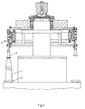
- the treatment machine shown in the drawing is intended for the treatment of bottles, namely part a labeling machine. It is also part of the tour their circumferential storage spaces for bottles 1 formed in which the bottles 1 axially between a Carrier plate 2 for the bottom of bottle 1 and one Centering bell 3 for the head of the bottle axially can be clamped.
- the carrier plate 2 is one Labeling machine designed as a turntable to the clamped bottle 1 on its treatment route in to bring different rotary positions.
- the Centering bell 3 is freely rotatable. For the lifting movement each centering bell 3 is one Lift mechanism 4 provided.
- the lifting mechanism 4 consists of a first one Guide rail 5, a package of arranged on it three coil springs 6a, 6b, 6c, each one from the other by flying on the guide rail 5 Guide bushings 7a, 7b are separated and located at the bottom End over a centering sleeve 8a on one on the Guide rail 5 axially fixed abutment 9 support.
- the spring assembly 6a, 6b, 6c is at the upper end flying over another guide bushing 8b on one the guide rail 5 supported abutment 10a supported, which is part of an actuator 10.
- the actuator 10 comprises a guide and support bracket 10b for a scanning roller 10c.
- the abutment 10a is part this guide and support bracket 10b.
- the leadership and Support bracket 10b is on a by means of sliding bushes 10d, 10e another guide rail 11 mounted on the frame 12 of the treatment machine is fixed. in the The machine frame is also the first guide rail 5 a guide bush 8c stored.
- the scanning roller 10c is by a consisting of coil springs 13a, 13b Spring assembly in contact with a one-sided cylindrical Curve 14 held.
- the spring assembly 13a, 13b is on its lower end via a guide sleeve 16a on one on the guide rail 11 axially fixed abutment 17a supported.
- the lifting mechanism 4 has two identical guide rails 11 with spring assemblies 13a, 13b on the jointly on the guide and support bracket 10b act.
- Figures 2a, 2b and 3a, 3b show two different ones Positions for the centering bell 3.
- the centering bell 3 is in one position raised position 14 because the cam 14 here has its upper range. Both are in this position Spring assemblies 6a, 6b, 6c, 13a, 13b if possible only preloaded, that is, they have their maximum possible in operation Feather length.
- Position with the lower section of the Control curve 14 is the guide and support bracket 10b after been relocated below. He has the guide rail 5 taken away. As soon as this move down the Centering bell 3 is placed on the head of bottle 1, the spring assembly 6a, 6b, 6c more or less, depending on Height of bottle 1, compressed.
- the guide bushes take care of movements 7a, 7b, 8a, 8b, 8c, 10d, 10e, 16a, 16b, 16c for making it too no contact of the springs 6a, 6b, 6c, 13a, 13b with the guide rails 5.11 comes. This will make a premature wear of the springs 6a, 6b, 6c, 13a, 13b of the Guide rods 5, 11 and their guide bushes 7a, 7b, 8a, 8b, 8c, 10d, 10e, 16a, 16b, 16c avoided.
- the springs 6a, 6b, 6c or 13a, 13b can be constructed from springs of different stiffness. However, it is preferably provided that the stroke is one the springs are mechanically limited. This can happen, for example, that the guide bushes strike before the full possible travel is exhausted.
Landscapes
- Engineering & Computer Science (AREA)
- Mechanical Engineering (AREA)
- Filling Of Jars Or Cans And Processes For Cleaning And Sealing Jars (AREA)
- Specific Conveyance Elements (AREA)
- Wrapping Of Specific Fragile Articles (AREA)
Description
- Figur 1
- eine Flaschenbehandlungsmaschine teilweise in Seitenansicht und teilweise im Axialschnitt,
- Figur 2a, 2b
- einen Hubmechanismus einer Einspannvorrichtung der Behandlungsmaschine nach Figur 1 in verschiedenen Funktionsstellungen in Seitenansicht,
- Figur 3a,3b
- den Hubmechanismus gemäß Figur 2a,2b in den beiden Funktionsstellungen in Vorderansicht.
Claims (5)
- Behandlungsmaschine für Behälter (1), insbesondere Flaschen, mit mehreren in Reihe hintereinander angeordneten und längs eines Behandlungsweges vorbewegten und dabei auf die Behälter (1) axial einwirkenden Einspannvorrichtungen, die jeweils aus einer Trägerplatte (2) für den Boden der Behälter (1) und einer auf den Kopf der Behälter (1) absenkbaren Zentrierglocke (3) bestehen, deren Hubbewegung von einem Hubmechanismus (4) mit einem bei der Vorbewegung der Einspannvorrichtung eine Raumkurve (14) abtastenden Stellglied (10c) gesteuert wird, wobei der Hubmechanismus (4) mindestens eine Führungsschiene (5,11) mit einer Feder (6a,6b,6c,13a,13c) für die axiale Hubbewegung der Zentrierglocke (3) aufweist,
dadurch gekennzeichnet , daß die Feder (6a,6b,6c,13a,13b) aus einem Paket von mehreren hintereinander liegenden kürzeren Federn besteht. - Behandlungsmaschine nach Anspruch 1,
dadurch gekennzeichnet , , daß auf einer Führungsschiene (11), die am Maschinengestell (12) fixiert ist, das Stellglied (10) axial verschiebbar gelagert ist, und daß eine weitere Führungsschiene (5), die die Zentrierglocke (3) trägt, axial verschiebbar im Maschinengestell (12) gelagert und am Stellglied (10) über das auf ihr gelagerte Federpaket (6a,6b,6c) abgestützt ist. - Behandlungsmaschine nach Anspruch 1 oder 2,
dadurch gekennzeichnet , , daß auf einer Führungsschiene (11), die am Maschinengestell (12) fixiert ist, das Stellglied (10) axial verschiebbar gelagert und das Federpaket (13a,13b) geführt und derart abgestützt ist, daß es das Stellglied (10) gegen die Raumkurve (14) drückt. - Behandlungsmaschine nach Anspruch 1,
dadurch gekennzeichnet , daß das Federpaket (6a,6b,6c,13a,13b) verschieden steife Federn umfaßt. - Behandlungsmaschine nach einem der Ansprüche 1 bis 4,
dadurch gekennzeichnet , daß der Hubweg mindestens einer Feder des Federpaketes (6a,6b,6c,13a,13b) durch ein Distanzelement begrenzt ist.
Applications Claiming Priority (3)
| Application Number | Priority Date | Filing Date | Title |
|---|---|---|---|
| DE29712254U | 1997-07-11 | ||
| DE29712254U DE29712254U1 (de) | 1997-07-11 | 1997-07-11 | Behandlungsmaschine für Behälter, insbesondere Flaschen, mit mehreren in Reihe hintereinander angeordneten Einspannvorrichtungen |
| PCT/EP1998/004206 WO1999002448A1 (de) | 1997-07-11 | 1998-07-07 | Behandlungsmaschine für behälter, insbesondere flaschen, mit einspannvorrichtung mit mehreren in reihe geschalteten federn |
Publications (2)
| Publication Number | Publication Date |
|---|---|
| EP0994822A1 EP0994822A1 (de) | 2000-04-26 |
| EP0994822B1 true EP0994822B1 (de) | 2001-09-05 |
Family
ID=8042981
Family Applications (1)
| Application Number | Title | Priority Date | Filing Date |
|---|---|---|---|
| EP98941301A Expired - Lifetime EP0994822B1 (de) | 1997-07-11 | 1998-07-07 | Behandlungsmaschine für behälter, insbesondere flaschen, mit einspannvorrichtung mit mehreren in reihe geschalteten federn |
Country Status (4)
| Country | Link |
|---|---|
| EP (1) | EP0994822B1 (de) |
| DE (1) | DE29712254U1 (de) |
| ES (1) | ES2163886T3 (de) |
| WO (1) | WO1999002448A1 (de) |
Families Citing this family (2)
| Publication number | Priority date | Publication date | Assignee | Title |
|---|---|---|---|---|
| DE10201025A1 (de) * | 2002-01-11 | 2003-07-31 | Odenwald Konserven Gmbh | Einlaufkurve mit Schiene zum Verarbeiten von Behälterglas mit doppelter Führungsnocke |
| CN102285617B (zh) * | 2011-07-29 | 2013-01-02 | 湖南汇一制药机械有限公司 | 一种内侧单刀式轧盖方法及其轧盖机构 |
Family Cites Families (9)
| Publication number | Priority date | Publication date | Assignee | Title |
|---|---|---|---|---|
| US2043578A (en) * | 1931-05-08 | 1936-06-09 | Mckenna Brass & Mfg Company In | Pump for eilling machines |
| FR1151265A (fr) * | 1956-06-07 | 1958-01-28 | égalisateur de niveau pour le remplissage des bouteilles | |
| FR1431602A (fr) * | 1965-04-27 | 1966-03-11 | Baele Sa Usine | Canule de soutirage d'un liquide dans un récipient |
| DE2033031A1 (de) * | 1970-07-03 | 1972-01-13 | Fa Hermann Heye, 4962 Obernkirchen | Element einer Maschine, z B Kronen korkverschließelement einer Kronenkorkver schließmaschine |
| DE2722254C3 (de) * | 1977-05-17 | 1980-08-07 | Seitz-Werke Gmbh, 6550 Bad Kreuznach | Flaschenverschließmaschine umlaufender Bauart |
| DE3446501A1 (de) * | 1984-12-20 | 1986-07-17 | Holstein Und Kappert Gmbh, 4600 Dortmund | Fuellventil zum abfuellen von fluessigkeiten unter gegendruck |
| DD272056A1 (de) * | 1988-05-02 | 1989-09-27 | Nagema Veb K | Vorrichtung zum verschliessen von flaschen mit kronenverschluessen |
| DE3933804A1 (de) * | 1989-10-10 | 1991-04-18 | Eti Tec Maschinenbau | Etikettiermaschine fuer flaschen mit einem haubenfreien flaschentraeger |
| DE4332325A1 (de) * | 1993-09-23 | 1995-03-30 | Alfill Getraenketechnik | Zentriervorrichtung für Behälterfüllmaschinen |
-
1997
- 1997-07-11 DE DE29712254U patent/DE29712254U1/de not_active Expired - Lifetime
-
1998
- 1998-07-07 ES ES98941301T patent/ES2163886T3/es not_active Expired - Lifetime
- 1998-07-07 EP EP98941301A patent/EP0994822B1/de not_active Expired - Lifetime
- 1998-07-07 WO PCT/EP1998/004206 patent/WO1999002448A1/de active IP Right Grant
Also Published As
| Publication number | Publication date |
|---|---|
| ES2163886T3 (es) | 2002-02-01 |
| WO1999002448A1 (de) | 1999-01-21 |
| DE29712254U1 (de) | 1998-11-05 |
| EP0994822A1 (de) | 2000-04-26 |
Similar Documents
| Publication | Publication Date | Title |
|---|---|---|
| EP2734462A1 (de) | Vorrichtung und verfahren zum stoppen und/oder ausrichten von transportgütern auf einer fördereinrichtung und fördereinrichtung | |
| DE3142378A1 (de) | "maschine zur selbsttaetigen montage von reifen auf felgen" | |
| DE3432380C2 (de) | ||
| DE19540914C2 (de) | Stromabnehmer für die Energieübertragung zwischen einem Fahrdraht und einem Triebwagen | |
| DE3016158C2 (de) | Hubbalkenförderer | |
| DE2944966C2 (de) | ||
| EP2329944B1 (de) | Presse zum Erzeugen einer Druckkraft für die Bearbeitung eines Werkstückes | |
| DE102005020978B4 (de) | Plattenaufteilanlage | |
| EP0994822B1 (de) | Behandlungsmaschine für behälter, insbesondere flaschen, mit einspannvorrichtung mit mehreren in reihe geschalteten federn | |
| EP0972878B1 (de) | Kalander für Bahnen aus Papier oder ähnlichem Material | |
| EP0972877B1 (de) | Kalander für Bahnen aus Papier oder ähnlichem Material | |
| EP1508430A2 (de) | Kontinuierliche Presse zum Pressen von Pressgutmatten oder Pressgutbahnen im Zuge der Herstellung von Spanplatten, Faserplatten oder dergleichen Holzwerkstoffplatten | |
| DE3109219A1 (de) | Umlenkvorrichtung fuer transportbahnen | |
| DE4210897C1 (de) | ||
| EP0972880A2 (de) | Kalander für Bahnen aus Papier oder ähnlichem Material | |
| DE2224875B2 (de) | Vorrichtung zum Belasten und Trennen der Walzen eines der Bearbeitung von Bahnen, insbesondere von Papierbahnen, dienenden Walzensatzes | |
| EP0979896B1 (de) | Kalanderanordnung für Bahnen aus Papier oder ähnlichem Material | |
| DE10305888A1 (de) | Hubbalkenautomatik | |
| EP1690672A2 (de) | Arbeitsstation mit einer gegenläufigen Hubbewegung zum Schliessen der Werkzeuge | |
| DE3004912C2 (de) | Kalander | |
| DE2758721A1 (de) | Reibungsverstaerkende endenausfuehrung fuer blattfedern | |
| DE2261848C2 (de) | ||
| DE892571C (de) | Spinnereimaschine, insbesondere Vorspinn-, Feinspinn- oder Zwirnmaschine, mit senkrecht bewegten Teilen | |
| DE102016216768A1 (de) | Fertigungsvorrichtung | |
| EP0310894B1 (de) | Schärmaschine |
Legal Events
| Date | Code | Title | Description |
|---|---|---|---|
| PUAI | Public reference made under article 153(3) epc to a published international application that has entered the european phase |
Free format text: ORIGINAL CODE: 0009012 |
|
| 17P | Request for examination filed |
Effective date: 19991228 |
|
| AK | Designated contracting states |
Kind code of ref document: A1 Designated state(s): ES FR GB IT |
|
| GRAG | Despatch of communication of intention to grant |
Free format text: ORIGINAL CODE: EPIDOS AGRA |
|
| 17Q | First examination report despatched |
Effective date: 20000918 |
|
| GRAG | Despatch of communication of intention to grant |
Free format text: ORIGINAL CODE: EPIDOS AGRA |
|
| GRAH | Despatch of communication of intention to grant a patent |
Free format text: ORIGINAL CODE: EPIDOS IGRA |
|
| GRAH | Despatch of communication of intention to grant a patent |
Free format text: ORIGINAL CODE: EPIDOS IGRA |
|
| GRAA | (expected) grant |
Free format text: ORIGINAL CODE: 0009210 |
|
| AK | Designated contracting states |
Kind code of ref document: B1 Designated state(s): ES FR GB IT |
|
| GBT | Gb: translation of ep patent filed (gb section 77(6)(a)/1977) |
Effective date: 20011026 |
|
| REG | Reference to a national code |
Ref country code: GB Ref legal event code: IF02 |
|
| REG | Reference to a national code |
Ref country code: ES Ref legal event code: FG2A Ref document number: 2163886 Country of ref document: ES Kind code of ref document: T3 |
|
| ET | Fr: translation filed | ||
| PLBE | No opposition filed within time limit |
Free format text: ORIGINAL CODE: 0009261 |
|
| STAA | Information on the status of an ep patent application or granted ep patent |
Free format text: STATUS: NO OPPOSITION FILED WITHIN TIME LIMIT |
|
| 26N | No opposition filed | ||
| PGFP | Annual fee paid to national office [announced via postgrant information from national office to epo] |
Ref country code: GB Payment date: 20050727 Year of fee payment: 8 Ref country code: FR Payment date: 20050727 Year of fee payment: 8 |
|
| PGFP | Annual fee paid to national office [announced via postgrant information from national office to epo] |
Ref country code: ES Payment date: 20050729 Year of fee payment: 8 |
|
| PG25 | Lapsed in a contracting state [announced via postgrant information from national office to epo] |
Ref country code: GB Free format text: LAPSE BECAUSE OF NON-PAYMENT OF DUE FEES Effective date: 20060707 |
|
| PGFP | Annual fee paid to national office [announced via postgrant information from national office to epo] |
Ref country code: IT Payment date: 20060731 Year of fee payment: 9 |
|
| GBPC | Gb: european patent ceased through non-payment of renewal fee |
Effective date: 20060707 |
|
| REG | Reference to a national code |
Ref country code: FR Ref legal event code: ST Effective date: 20070330 |
|
| REG | Reference to a national code |
Ref country code: ES Ref legal event code: FD2A Effective date: 20060708 |
|
| PG25 | Lapsed in a contracting state [announced via postgrant information from national office to epo] |
Ref country code: ES Free format text: LAPSE BECAUSE OF NON-PAYMENT OF DUE FEES Effective date: 20060708 |
|
| PG25 | Lapsed in a contracting state [announced via postgrant information from national office to epo] |
Ref country code: FR Free format text: LAPSE BECAUSE OF NON-PAYMENT OF DUE FEES Effective date: 20060731 |
|
| PG25 | Lapsed in a contracting state [announced via postgrant information from national office to epo] |
Ref country code: IT Free format text: LAPSE BECAUSE OF NON-PAYMENT OF DUE FEES Effective date: 20070707 |