EP0994555B1 - Machine élèctrique sous-synchrone à réluctance - Google Patents
Machine élèctrique sous-synchrone à réluctance Download PDFInfo
- Publication number
- EP0994555B1 EP0994555B1 EP99119802A EP99119802A EP0994555B1 EP 0994555 B1 EP0994555 B1 EP 0994555B1 EP 99119802 A EP99119802 A EP 99119802A EP 99119802 A EP99119802 A EP 99119802A EP 0994555 B1 EP0994555 B1 EP 0994555B1
- Authority
- EP
- European Patent Office
- Prior art keywords
- stator
- rotor
- teeth
- sector
- coil
- Prior art date
- Legal status (The legal status is an assumption and is not a legal conclusion. Google has not performed a legal analysis and makes no representation as to the accuracy of the status listed.)
- Expired - Lifetime
Links
Images


Classifications
-
- H—ELECTRICITY
- H02—GENERATION; CONVERSION OR DISTRIBUTION OF ELECTRIC POWER
- H02K—DYNAMO-ELECTRIC MACHINES
- H02K1/00—Details of the magnetic circuit
- H02K1/06—Details of the magnetic circuit characterised by the shape, form or construction
- H02K1/12—Stationary parts of the magnetic circuit
- H02K1/14—Stator cores with salient poles
-
- H—ELECTRICITY
- H02—GENERATION; CONVERSION OR DISTRIBUTION OF ELECTRIC POWER
- H02K—DYNAMO-ELECTRIC MACHINES
- H02K19/00—Synchronous motors or generators
- H02K19/02—Synchronous motors
- H02K19/10—Synchronous motors for multi-phase current
- H02K19/103—Motors having windings on the stator and a variable reluctance soft-iron rotor without windings
-
- H—ELECTRICITY
- H02—GENERATION; CONVERSION OR DISTRIBUTION OF ELECTRIC POWER
- H02K—DYNAMO-ELECTRIC MACHINES
- H02K29/00—Motors or generators having non-mechanical commutating devices, e.g. discharge tubes or semiconductor devices
- H02K29/06—Motors or generators having non-mechanical commutating devices, e.g. discharge tubes or semiconductor devices with position sensing devices
Definitions
- the present invention relates to a new reluctance electric machine and, more particularly, to a rotating or linear subsynchronous reluctance machine.
- Brasilian patent application Pl9400880-9 published on 10/24/95 and relating to "Reluctance electrical machine” has been proposed, which provided an electrical machine comprised of a rotor and a stator.
- Said stator was provided with a core comprised of magnetic plates and provided with longitudinal teeth projecting towards the rotor.
- Said stator also comprised a plurality of grooves capable of receiving a multi-phase winding, said winding being comprised of a plurality of coils homogeneously surrounding the stator's magnetic material.
- said rotor was formed by a core of magnetic plates provided with longitudinal teeth projecting towards the stator.
- an electrical motor with variable reluctance and electronic commutation comprising a stator ring containing contacts provided with coils, the number of which is a multiple of the product of the number of commutators times the number 4 (pattern 4), and a rotor ring containing teeth, the number of which is the same multiple of a prime number greater than the product "commutators x pattern 4", the rings being produced by stacking metal sheets cut out respectively as sectors of 2 to 5 teeth and as sectors of 2 to 5 contacts; the residual air gaps formed by the side-by-side placement of the said sectors are located substantially in the median part of the contacts and of the teeth respectively.
- This characteristic makes it possible to eradicate the parasitic reluctance due to the assembly of metal sheets cut out sectorially in the rings.
- US-A-4,995,159 discloses a motor structure and energization scheme providing a high efficiency electronically commutated reluctance motor that is characterized by less iron losses than conventional switched reluctance motors.
- the motor operates without the reversal of the flow of flux in the stator.
- the flux switching frequency in the stator is minimized.
- the electronically commutated reluctance motor is operable over a wide range of speeds with improved efficiency.
- the stator includes unevenly spaced poles which are grouped into pairs separated by a space related to the even spacing of the poles on the rotor.
- Adjacent pairs of poles on the stator are separated by a spacing which is not equal to the spacing between the poles of a pair.
- each pair of poles on the stator is polarized to form poles of opposite polarity such that a magnetic circuit joins the two adjacent poles of the pair.
- Magnetic circuits linking different pairs of stator poles which are the source flux reversals and high switching frequencies in conventional motors, are prevented by providing a stator construction that is without low reluctance paths between adjacent pairs of stator poles.
- Another object of the present invention is to provide a reluctance electrical machine that, by reason of its constructive features, does not present oscillations in the resulting torque and speed.
- Another object of the present invention is to provide an improvement on the reluctance electrical machine as per the above referenced Brasilian patent application PI 9400880-9, having characteristics of a high power factor.
- the number of teeth on the rotor is necessarily different from the number of teeth on the stator.
- the machine is provided with a device for monitoring and identifying the relative position between the stator and rotor teeth in order to allow the identification of the region of largest magnetic permeability between the rotor and the stator, in order to allow the proper feeding of the stator coils, thereby obtaining the maximum possible torque.
- the present invention has constructive characteristics similar to those of the machine described on Brasilian patent application Pl9400880-9, however it is fundamentally different therefrom in the following items:
- the present invention provides a sub-synchronous reluctance electrical machine of the type comprising at least one rotor formed of ferromagnetic plates and provided with a plurality of uniformly distributed teeth and at least a stator provided on the surface thereof facing said rotor with a second plurality of teeth, also uniformly arranged, plus coils, said coils being selectively fed by a current power source, and the at least one stator is formed by a series of magnetically uncoupled or weakly coupled sectors of ferromagnetic plates, each sector comprising one coil, the coil of each sector having the power thereof controlled by a monitoring device, and the number of teeth on the stator being different from the number of teeth on the rotor.
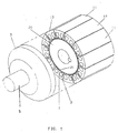
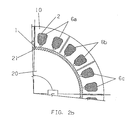
- the reluctance electrical machine of the present invention is conceptually defined by a stator 10 provided with a core comprised of magnetically uncoupled or weakly coupled ferromagnetic plate sectors 11 having longitudinal teeth 1 arranged on the face thereof turned towards the rotor 20 and provided with grooves 2 for housing one or more windings 6, 6'.
- These windings 6, 6' are composed of a plurality of coils 6a, 6b, 6c, 6d, ... surrounding the magnetic material of stator 10, in order to generate a magnetic field whenever this winding is energized.
- FIG. 1 As an integral part of the sub-synchronous reluctance electrical machine is said rotor 20 which is in turn provided with a core of ferromagnetic plates having longitudinal teeth 21 uniformly arranged along the face thereof turned towards the stator 10, said teeth 21 being in a number different from the number of teeth 1 of stator 10.
- Figures 1-2 shown a sub-synchronous rotating motor the shell 3 of which fixedly houses a stator 10 within which a rotor 20 is arranged supported by shaft 5.
- the stator 10 is formed by a plurality of magnetically uncoupled or weakly coupled sectors 11, and is formed of ferromagnetic plates, the surface facing the rotor 20 being provided with a plurality of teeth 1.
- stator is provided with a series of grooves 2 within which the coils 6a, 6b, 6c, 6d, ... forming the winding 6 are arranged.
- rotor 20 formed of ferromagnetic plates, is provided with a plurality of teeth 21 on the surface thereof facing the stator 10, the number of teeth 21 of rotor 20 being different from the number of teeth 1 of stator 10.
- Figures 3-4 illustrate a motor similar to the one described above, differing therefrom only in that the stator 10 is internal and supported by shaft 5, whereas the rotor 20 is attached to the motor shell 3.
- Figures 5-6 illustrate in a very schematic manner a linear motor wherein the stator 10 and the rotor 20 face each other by means of respective teeth 1 and 21.
- the stator 10 in accordance with the invention is formed of uncoupled or weakly coupled sectors, and the coils 6a, 6a, 6c, 6d, ... are housed within each sector.
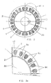
- Figures 7-8 in turn illustrate also in a schematic manner a sub-synchronous disc motor, wherein rotor 20 is attached to the motor shaft 5 and faces the stator 10 by means of the respective teeth 21 and 1.
- the stator 10 is formed of a plurality of uncoupled sectors 11, in this case illustrated by only two sectors 11, each provided with grooves to receive the coils of the winding 6. Said coils are maintained within each of the sectors 11 of stator 10, specifically inside the respective grooves 2.
- Figure 9 illustrate a sub-synchronous reluctance motor of two stators 10, 10' and two windings 6, 6'.
- said motor is formed of a first, external stator 10 attached to shell 3, which surrounds a rotor 20 attached to shaft 5, in a known manner.
- Said stator 10 is provided with a series of internal teeth 1 which face a series of external teeth 21 of rotor 20.
- Said rotor 20 is provided internally thereof with a second series of teeth 21' which face a series of teeth 1' of the second stator 10'.
- the stators 10,10' are fixed and have the respective sectors 11, 11' cooperating in an angular position, as are cooperating the respective windings 6, 6'.
- the machine is further provided with a monitoring device 4 for relative identification of the teeth of rotor 20 and the teeth of stator 10, as shown on Figure 10.
- Such device can be for example a resolver or an encoder, and is capable of determining the relative position between the teeth 1 of stator 10 and teeth 21 of rotor 20.
- this monitoring device 4 can be comprised, for example, of a position detector based on Hall effect, property attached to the stator.
- the speed of rotor 20 is a function of the number of teeth of said rotor 20 and a function of the triggering frequency of the power source (not illustrated), that is, in a more specific manner, the speed of rotor 20 is directly proportional to the triggering speed of the power source and inversely proportional to the number of teeth 21 of rotor 20. Accordingly, it can be concluded that with a proper selection of the number of teeth 21 of rotor 20 it is easy to obtain any rated rotation or speed. Any type of power source for the winding 6 of stator 10 can be used .
- said power source should have as a feature thereof the that it is controlled by the monitoring device 4 either directly or indirectly, thereby to feed the coils 6a, 6b, 6c, 6d, ... of sectors 11, according to the relative position between stator 10 and rotor 20.
- the monitoring device 4 in addition to the preferred types described above, use could be made of any device capable of accurately determining the relative position between stator 10 and rotor 20, and that may control a power source for the coils 6a, 6b, 6c, 6d, ..., either directly or through an interface.
- the internal position adopted for the winding 6 can also be modified, such as, for example, by arranging the coils thereof around the teeth 1 of stator 10. Another alternative is arranging the coils of the winding 6 around each of the sectors 11, thereby completely surrounding each said sector 11.
- each sector may comprise more than one coil, each fed separately by a respective power source.
Landscapes
- Engineering & Computer Science (AREA)
- Power Engineering (AREA)
- Synchronous Machinery (AREA)
- Linear Motors (AREA)
- Developing Agents For Electrophotography (AREA)
- Organic Insulating Materials (AREA)
- Brushless Motors (AREA)
Claims (8)
- Une méthode pour opérer un moteur électrique à réluctance sous synchrone qui comprend au moins un rotor (20) et au moins un stator (10) ayant un bobinage (6) qui est formé par une pluralité de bobines (6a, 6b, 6c), où:la méthode étant caractérisée par l'étape de dépistage d'une position relative dudit rotor (20) en ce qui concerne ledit secteur du stator (11) et par le fait d'activer séquentiellement lesdites bobines (6a, 6b, 6c) selon les phases d'actionnement suivantes:ledit rotor (20) est formé de plaques ferromagnétiques et est fourni d'une pluralité de dents de rotor longitudinales (21A, 21B, 21E) qui sont uniformément distribuées au-dessus d'une surface du rotor faisant face au stator (10) susmentionné, lesdites dents du rotor (21A, 21B, 21E) étant en surplomb vers ledit stator (10),ledit stator (10) est formé d'une série de secteurs de stator (11), non couplés ou faiblement couplés, arrangés côte à côte et faits de plaques ferromagnétiques, chaque secteur du stator (11) étant fourni d'une pluralité de dents de stator longitudinales (1A, 1E, 1I) qui sont uniformément distribuées au-dessus d'une surface du stator faisant face audit rotor (20), lesdites dents du stator (1A, 1E, 1I) étant en surplomb vers lesdites dents du rotor (21A, 21B, 21E),chaque secteur du stator (11) est fourni d'une bobine de cette pluralité de bobines ( 6a, 6b, 6 c) susmentionnée, la bobine susmentionnée étant arrangée de façon à entourer le matériel ferromagnétique du secteur du stator respectif (11) pour créer un champ magnétique quand ladite bobine est activée par l'intermédiaire d'une source d'énergie courante, etle nombre total de dents du stator (1A, 1E, 1I) est différent du nombre de dents du rotor (21A, 21B, 21E);a) identification d'une région de grande perméabilité entre une dent du stator (1A) d'un premier secteur du stator (11) et une première dent du rotor (21A), cette région de grande perméabilité existe si ladite dent du stator (1A) étant alignée avec ladite dent du rotor (21A),
activer une première bobine (6a) du premier secteur du stator (11) avec une deuxième bobine (6b) d'un deuxième secteur du stator (11), ledit deuxième secteur du stator (11) étant adjacent audit premier secteur du stator (11) dans la direction opposée à la direction de mouvement dudit rotor (20), l'état d'activation desdites première et deuxième bobines (6a, 6b) causant le déplacement dudit rotor (20) en ce qui concerne ledit stator (10);b) identification d'une région de grande perméabilité entre u ne dent de stator (1E) d'un deuxième secteur du stator (11) et une deuxième dent de rotor (21E), cette région de grande perméabilité existe si ladite dent du stator (1E) étant alignée avec ladite dent du rotor (21 E),
désactiver ladite première bobine (6a),
maintenir activée ladite deuxième bobine (6b),
activer une troisième bobine (6c) d'un troisième secteur du stator (11), ledit troisième secteur du stator (11) étant adjacent audit deuxième secteur du stator (11) dans la direction opposée à la direction du mouvement dudit rotor (20), l'état d'activation desdites deuxième et troisièmes bobines (6b, 6c) causant un déplacement supplémentaire dudit rotor (20) en ce qui concerne ledit stator (10); etc) activer et désactiver sélectivement des bobines (6a, 6b, 6c) de n'importe quel secteur du stator (11) selon la phase d'actionnement b), afin de maintenir des bobines (6a, 6b, 6c) toujours activées de deux secteurs adjacents du stator (11) pour produire une séquence de mouvements dudit rotor (20) en ce qui concerne ledit stator (10). - Un moteur électrique à réluctance sous synchrone qui comprend au moins un rotor (20) et au moins un stator (10) ayant un bobinage (6) qui est formé par une pluralité de bobines (6a, 6b, 6c), où :caractérisé par le fait qu'il comprend un dispositif de contrôle (4) en vigueur pour dépister une position relative dudit rotor (20) en ce qui concerne ledit secteur du stator (11) et par le fait d'activer séquentiellement lesdites bobines (6a, 6b, 6c) selon les phases d'actionnement suivantes:ledit rotor (20) est formé de plaques ferromagnétiques et est fourni d'une pluralité de dents de rotor longitudinales (21A, 21B, 21E) qui sont uniformément distribuées au-dessus d'une surface du rotor faisant face au stator (10) susmentionné, lesdites dents du rotor (21 A, 21B, 21E) étant en surplomb vers ledit stator (10),ledit stator (10) est formé d'une série de secteurs de stator (11), non couplés ou faiblement couplés, arrangés côte à côte et faits de plaques ferromagnétiques, chaque secteur du stator (11) étant fourni d'une pluralité de dents de stator longitudinales (1A, 1E, 1I) qui sont uniformément distribuées au-dessus d'une surface du stator faisant face au rotor (20) susmentionné, lesdites dents du stator (1A, 1E, 1I) étant en surplomb vers lesdites dents du rotor (21A, 21B, 21E),chaque secteur du stator (11) est fourni d'une bobine de ladite pluralité de bobines (6a, 6b, 6c), la bobine susmentionnée étant arrangée de façon à entourer le matériel ferromagnétique du secteur du stator respectif (11) pour créer un champ magnétique quand ladite bobine est activée par l'intermédiaire d'une source d'énergie courante, etle nombre total de dents du stator (1A, 1E, 1I) est différent du nombre de dents du rotor (21A, 21B, 21E);a) identification d'une région de grande perméabilité entre une dent du stator (1A) d'un premier secteur du stator (11) et une première dent du rotor (21A), cette région de grande perméabilité existe si ladite dent du stator (1A) étant alignée avec ladite dent du rotor (21A),
activer une première bobine (6a) du premier secteur du stator (11) avec une deuxième bobine (6b) d'un deuxième secteur du stator (11), ledit deuxième secteur du stator (11) étant adjacent audit premier secteur du stator (11) dans la direction opposée à la direction de mouvement dudit rotor (20), l'état d'activation desdites première et deuxième bobines (6a, 6b) causant le déplacement dudit rotor (20) en ce qui concerne ledit stator (10);b) identification d'une région de grande perméabilité entre u ne dent de stator (1E) d'un deuxième secteur du stator (11) et une deuxième dent de rotor (21E), cette région de grande perméabilité existe si ladite dent du stator (1E) étant alignée avec ladite dent du rotor (21E),
désactiver ladite première bobine (6a),
maintenir activée ladite deuxième bobine (6b),
activer une troisième bobine (6c) d'un troisième secteur du stator (11), ledit troisième secteur du stator (11) étant adjacent audit deuxième secteur du stator (11) dans la direction opposée à la direction du mouvement dudit rotor (20), l'état d'activation desdites deuxième et troisièmes bobines (6b, 6c) causant un déplacement supplémentaire d udit rotor (20) en ce qui concerne ledit stator (10); etc) activer et désactiver sélectivement des bobines (6a, 6b, 6c) de n'importe quel secteur du stator (11) selon la phase d'actionnement b), afin de maintenir des bobines (6a, 6b, 6c) toujours activées de deux secteurs adjacents du stator (11) pour produire une séquence de mouvements dudit rotor (20) en ce qui concerne ledit stator (10). - Machine conformément à la revendication 2, caractérisée par le fait que chaque bobine (6a, 6b, 6c) est arrangée dans au moins deux rainures (2) du secteur respectif (11) dudit stator (10).
- Machine conformément à la revendication 2, caractérisée par le fait que ledit dispositif de contrôle (4) est un détecteur du type Hall.
- Machine conformément à la revendication 2, caractérisée par le fait que ledit dispositif de contrôle (4) est un encodeur ou un résolveur.
- Machine conformément à la revendication 2, caractérisée par le fait qu'elle est un moteur rotatif à réluctance sous synchrone.
- Machine conformément à la revendication 2, caractérisée par le fait qu'elle est un moteur linéaire à réluctance sous synchrone.
- Machine conformément à la revendication 2, caractérisée par le fait qu'elle est un moteur à disque à réluctance sous synchrone.
Applications Claiming Priority (5)
| Application Number | Priority Date | Filing Date | Title |
|---|---|---|---|
| BR9804426 | 1998-10-16 | ||
| BR9804426-5A BR9804426A (pt) | 1998-10-16 | 1998-10-16 | Máquina elétrica de relutância subsìncrona. |
| JP2000008195A JP2001204162A (ja) | 1998-10-16 | 2000-01-17 | 次同期リラクタンス電気機械 |
| CA002297337A CA2297337C (fr) | 1998-10-16 | 2000-01-27 | Machine electrique a reluctance hyposynchrone |
| CN00100707A CN1307394A (zh) | 1998-10-16 | 2000-02-01 | 次同步磁阻电机 |
Publications (3)
| Publication Number | Publication Date |
|---|---|
| EP0994555A2 EP0994555A2 (fr) | 2000-04-19 |
| EP0994555A3 EP0994555A3 (fr) | 2001-05-16 |
| EP0994555B1 true EP0994555B1 (fr) | 2004-05-26 |
Family
ID=27425285
Family Applications (1)
| Application Number | Title | Priority Date | Filing Date |
|---|---|---|---|
| EP99119802A Expired - Lifetime EP0994555B1 (fr) | 1998-10-16 | 1999-10-06 | Machine élèctrique sous-synchrone à réluctance |
Country Status (11)
| Country | Link |
|---|---|
| US (1) | US6239530B1 (fr) |
| EP (1) | EP0994555B1 (fr) |
| JP (2) | JP2000152579A (fr) |
| KR (1) | KR100633706B1 (fr) |
| CN (1) | CN1307394A (fr) |
| AT (1) | ATE268068T1 (fr) |
| BR (1) | BR9804426A (fr) |
| CA (1) | CA2297337C (fr) |
| DE (1) | DE69917557T2 (fr) |
| ES (1) | ES2222648T3 (fr) |
| PT (1) | PT994555E (fr) |
Families Citing this family (26)
| Publication number | Priority date | Publication date | Assignee | Title |
|---|---|---|---|---|
| FR2806951B1 (fr) * | 2000-03-31 | 2002-06-14 | Aro | Dispositif de motorisation electrique pour pince d'outillage |
| US6648252B2 (en) * | 2000-10-04 | 2003-11-18 | Emerson Electric Co. | Switched reluctance machine and food waste disposer employing switched reluctance machine |
| US6481652B2 (en) | 2000-11-28 | 2002-11-19 | Emerson Electric Co. | Food waste disposer having variable speed motor and methods of operating same |
| US6854673B2 (en) * | 2000-11-28 | 2005-02-15 | Emerson Electric Co. | Food waste disposer having a variable speed motor |
| US7012350B2 (en) * | 2001-01-04 | 2006-03-14 | Emerson Electric Co. | Segmented stator switched reluctance machine |
| US6584813B2 (en) | 2001-03-26 | 2003-07-01 | Emerson Electric Co. | Washing machine including a segmented stator switched reluctance motor |
| US20020093269A1 (en) * | 2001-01-16 | 2002-07-18 | Harter Bernard G. | Slot area undercut for segmented stators |
| US6744166B2 (en) * | 2001-01-04 | 2004-06-01 | Emerson Electric Co. | End cap assembly for a switched reluctance electric machine |
| US6700284B2 (en) * | 2001-03-26 | 2004-03-02 | Emerson Electric Co. | Fan assembly including a segmented stator switched reluctance fan motor |
| US6897591B2 (en) * | 2001-03-26 | 2005-05-24 | Emerson Electric Co. | Sensorless switched reluctance electric machine with segmented stator |
| GB0209794D0 (en) * | 2002-04-30 | 2002-06-05 | Univ Newcastle | Switched reluctance electrical machine |
| DE102006005046A1 (de) * | 2006-02-03 | 2007-08-09 | Siemens Ag | Elektrische Maschine mit ungleichmäßigen Polzähnen |
| EP2171827A1 (fr) * | 2007-07-27 | 2010-04-07 | The Texas A&M University System | Moteurs/générateurs à court trajet de flux |
| CN101465588B (zh) * | 2007-12-21 | 2015-05-13 | 张玉宝 | 一种磁阻电动机及提高电动机有效功率的方法 |
| US7851966B2 (en) * | 2008-01-10 | 2010-12-14 | Rippel Wally E | Stator for electric machine with improved efficiency and thermal performance |
| JP4747184B2 (ja) * | 2008-04-14 | 2011-08-17 | 本田技研工業株式会社 | 電動機 |
| JP4505524B2 (ja) * | 2008-07-22 | 2010-07-21 | 本田技研工業株式会社 | 動力装置 |
| CN102160267B (zh) * | 2008-08-29 | 2013-08-21 | 莫戈公司 | 永磁型步进电动机 |
| CN102239626B (zh) * | 2009-09-08 | 2015-01-28 | 莫戈公司 | 带有小步幅间隔的步进马达 |
| FR2961970B1 (fr) * | 2010-06-25 | 2017-03-10 | Valeo Systemes De Controle Moteur | Moteur electrique a courant alternatif d'un dispositif electrique combine d'alimentation et de charge |
| DE102012103677A1 (de) * | 2012-04-26 | 2013-10-31 | Feaam Gmbh | Elektrische Maschine |
| RU2543522C2 (ru) * | 2013-07-23 | 2015-03-10 | Общество с ограниченной ответственностью "Механотроника" | Мехатронное устройство |
| US11255612B2 (en) | 2014-07-25 | 2022-02-22 | Enure, Inc. | Wound strip machine |
| DE112015003443T5 (de) | 2014-07-25 | 2017-04-06 | Prippell Technologies, Llc | Fluidgekühlte gewundene Streifenstruktur |
| US10756583B2 (en) | 2014-07-25 | 2020-08-25 | Enure, Inc. | Wound strip machine |
| DE102017105977A1 (de) * | 2017-03-21 | 2018-09-27 | Schaeffler Technologies AG & Co. KG | Dynamoelektrische Maschine mit reduzierten Rastmomenten |
Family Cites Families (14)
| Publication number | Priority date | Publication date | Assignee | Title |
|---|---|---|---|---|
| US4315171A (en) * | 1977-05-23 | 1982-02-09 | Ernest Schaeffer | Step motors |
| US4198582A (en) * | 1977-06-24 | 1980-04-15 | Exxon Research & Engineering Co. | High performance stepper motor |
| US4475051A (en) * | 1982-08-27 | 1984-10-02 | International Business Machines Corporation | Low inertia high torque variable reluctance motor |
| FR2573586B1 (fr) * | 1984-11-19 | 1988-08-05 | Jarret Tech Electr | Perfectionnements aux moteurs a reluctance variable |
| US5173651A (en) * | 1985-06-28 | 1992-12-22 | Kollmorgen Technologies Corporation | Electrical drive systems |
| US4713570A (en) * | 1986-06-04 | 1987-12-15 | Pacific Scientific Co. | Magnetically enhanced variable reluctance motor systems |
| US4733117A (en) * | 1987-04-27 | 1988-03-22 | The Superior Electric Company | Reluctance synchro/resolver |
| US4990809A (en) * | 1987-04-27 | 1991-02-05 | The Superior Electric Company | Variable reluctance motor |
| US4995159A (en) * | 1988-08-15 | 1991-02-26 | Pacific Scientific Company | Method of making an electronically commutated reluctance motor |
| JP2599061B2 (ja) * | 1991-12-13 | 1997-04-09 | オリエンタルモーター株式会社 | ステッピングモータ |
| IT1262572B (it) * | 1993-11-03 | 1996-07-04 | Alessandro Dreoni | Motore elettrico lineare o rotativo sincrono a riluttanza variabile con sviluppo volumetrico della forza |
| US6025668A (en) * | 1995-12-08 | 2000-02-15 | Dana Corporation | Variable reluctance motor having bifurcated stator poles |
| DE19743380C1 (de) * | 1997-09-30 | 1999-03-25 | Emf 97 Gmbh | Reluktanzmotor |
| US6051898A (en) * | 1998-01-02 | 2000-04-18 | Japan Servo Co., Ltd. | Stepping motor having external rotor and electromagnetic-combined-permanent-magnet stator |
-
1998
- 1998-10-16 BR BR9804426-5A patent/BR9804426A/pt not_active Application Discontinuation
-
1999
- 1999-09-29 US US09/408,298 patent/US6239530B1/en not_active Expired - Lifetime
- 1999-10-06 ES ES99119802T patent/ES2222648T3/es not_active Expired - Lifetime
- 1999-10-06 AT AT99119802T patent/ATE268068T1/de not_active IP Right Cessation
- 1999-10-06 PT PT99119802T patent/PT994555E/pt unknown
- 1999-10-06 EP EP99119802A patent/EP0994555B1/fr not_active Expired - Lifetime
- 1999-10-06 DE DE69917557T patent/DE69917557T2/de not_active Expired - Lifetime
- 1999-10-12 KR KR1019990044156A patent/KR100633706B1/ko not_active IP Right Cessation
- 1999-10-18 JP JP11295559A patent/JP2000152579A/ja active Pending
-
2000
- 2000-01-17 JP JP2000008195A patent/JP2001204162A/ja active Pending
- 2000-01-27 CA CA002297337A patent/CA2297337C/fr not_active Expired - Fee Related
- 2000-02-01 CN CN00100707A patent/CN1307394A/zh active Pending
Also Published As
| Publication number | Publication date |
|---|---|
| PT994555E (pt) | 2004-10-29 |
| CN1307394A (zh) | 2001-08-08 |
| ES2222648T3 (es) | 2005-02-01 |
| ATE268068T1 (de) | 2004-06-15 |
| JP2001204162A (ja) | 2001-07-27 |
| EP0994555A2 (fr) | 2000-04-19 |
| US6239530B1 (en) | 2001-05-29 |
| CA2297337A1 (fr) | 2001-07-27 |
| JP2000152579A (ja) | 2000-05-30 |
| DE69917557D1 (de) | 2004-07-01 |
| BR9804426A (pt) | 2000-05-16 |
| KR20000029016A (ko) | 2000-05-25 |
| CA2297337C (fr) | 2008-04-08 |
| KR100633706B1 (ko) | 2006-10-13 |
| DE69917557T2 (de) | 2005-07-14 |
| EP0994555A3 (fr) | 2001-05-16 |
Similar Documents
| Publication | Publication Date | Title |
|---|---|---|
| EP0994555B1 (fr) | Machine élèctrique sous-synchrone à réluctance | |
| JP5318758B2 (ja) | リングコイルモータ | |
| US4719378A (en) | Brushless motor having permanent magnet rotor and salient pole stator | |
| US4197488A (en) | Electrical machine | |
| US4990809A (en) | Variable reluctance motor | |
| US4995159A (en) | Method of making an electronically commutated reluctance motor | |
| EP0559818B1 (fr) | Moteur polyphase a reluctance et a commutation | |
| US4237396A (en) | Electromagnetic machines with permanent magnet excitation | |
| US6683397B2 (en) | Electric machine having at least one magnetic field detector | |
| KR101228013B1 (ko) | 비대칭 극을 갖는 직류 모터 | |
| JP3693100B2 (ja) | 多相トラバース磁束機械 | |
| JPS6341307B2 (fr) | ||
| US4823039A (en) | Electrical machines | |
| EP0465462A4 (en) | Electronically commutated reluctance motor | |
| US4978878A (en) | Electric multipolar machine | |
| US20130057105A1 (en) | Permanent magnet motors and methods of assembling the same | |
| EP0848482A2 (fr) | Moteurs à courant continu sans balai | |
| US6975057B2 (en) | Rotary electric machine having a stator made up of sectors assembled together | |
| US8373328B2 (en) | Pulsed multi-rotor constant air gap switched reluctance motor | |
| KR100337665B1 (ko) | 영구자석전동기 | |
| EP0735652A1 (fr) | Machine à reluctance commutée | |
| WO2022020226A1 (fr) | Moteur pas à pas à réluctance variable ayant un couple de maintien amélioré | |
| US5438227A (en) | Linear pulse motor | |
| JP4248778B2 (ja) | 永久磁石形電動機の回転子 | |
| US4608505A (en) | Commutatorless d.c. electric motor |
Legal Events
| Date | Code | Title | Description |
|---|---|---|---|
| PUAI | Public reference made under article 153(3) epc to a published international application that has entered the european phase |
Free format text: ORIGINAL CODE: 0009012 |
|
| AK | Designated contracting states |
Kind code of ref document: A2 Designated state(s): AT BE CH CY DE DK ES FI FR GB GR IE IT LI LU MC NL PT SE |
|
| AX | Request for extension of the european patent |
Free format text: AL;LT;LV;MK;RO;SI |
|
| PUAL | Search report despatched |
Free format text: ORIGINAL CODE: 0009013 |
|
| AK | Designated contracting states |
Kind code of ref document: A3 Designated state(s): AT BE CH CY DE DK ES FI FR GB GR IE IT LI LU MC NL PT SE |
|
| AX | Request for extension of the european patent |
Free format text: AL;LT;LV;MK;RO;SI |
|
| 17P | Request for examination filed |
Effective date: 20010920 |
|
| 17Q | First examination report despatched |
Effective date: 20011109 |
|
| AKX | Designation fees paid |
Free format text: AT BE CH CY DE DK ES FI FR GB GR IE IT LI LU MC NL PT SE |
|
| GRAH | Despatch of communication of intention to grant a patent |
Free format text: ORIGINAL CODE: EPIDOS IGRA |
|
| RAP1 | Party data changed (applicant data changed or rights of an application transferred) |
Owner name: INVENTIO AG |
|
| GRAS | Grant fee paid |
Free format text: ORIGINAL CODE: EPIDOSNIGR3 |
|
| GRAA | (expected) grant |
Free format text: ORIGINAL CODE: 0009210 |
|
| AK | Designated contracting states |
Kind code of ref document: B1 Designated state(s): AT BE CH CY DE DK ES FI FR GB GR IE IT LI LU MC NL PT SE |
|
| PG25 | Lapsed in a contracting state [announced via postgrant information from national office to epo] |
Ref country code: CY Free format text: LAPSE BECAUSE OF FAILURE TO SUBMIT A TRANSLATION OF THE DESCRIPTION OR TO PAY THE FEE WITHIN THE PRESCRIBED TIME-LIMIT Effective date: 20040526 |
|
| REG | Reference to a national code |
Ref country code: GB Ref legal event code: FG4D |
|
| REG | Reference to a national code |
Ref country code: CH Ref legal event code: EP |
|
| REG | Reference to a national code |
Ref country code: IE Ref legal event code: FG4D |
|
| REF | Corresponds to: |
Ref document number: 69917557 Country of ref document: DE Date of ref document: 20040701 Kind code of ref document: P |
|
| PG25 | Lapsed in a contracting state [announced via postgrant information from national office to epo] |
Ref country code: GR Free format text: LAPSE BECAUSE OF FAILURE TO SUBMIT A TRANSLATION OF THE DESCRIPTION OR TO PAY THE FEE WITHIN THE PRESCRIBED TIME-LIMIT Effective date: 20040826 Ref country code: DK Free format text: LAPSE BECAUSE OF FAILURE TO SUBMIT A TRANSLATION OF THE DESCRIPTION OR TO PAY THE FEE WITHIN THE PRESCRIBED TIME-LIMIT Effective date: 20040826 |
|
| REG | Reference to a national code |
Ref country code: SE Ref legal event code: TRGR |
|
| PG25 | Lapsed in a contracting state [announced via postgrant information from national office to epo] |
Ref country code: LU Free format text: LAPSE BECAUSE OF NON-PAYMENT OF DUE FEES Effective date: 20041006 Ref country code: IE Free format text: LAPSE BECAUSE OF NON-PAYMENT OF DUE FEES Effective date: 20041006 |
|
| REG | Reference to a national code |
Ref country code: PT Ref legal event code: SC4A Free format text: AVAILABILITY OF NATIONAL TRANSLATION Effective date: 20040820 |
|
| PG25 | Lapsed in a contracting state [announced via postgrant information from national office to epo] |
Ref country code: MC Free format text: LAPSE BECAUSE OF NON-PAYMENT OF DUE FEES Effective date: 20041031 |
|
| ET | Fr: translation filed | ||
| REG | Reference to a national code |
Ref country code: ES Ref legal event code: FG2A Ref document number: 2222648 Country of ref document: ES Kind code of ref document: T3 |
|
| PLBE | No opposition filed within time limit |
Free format text: ORIGINAL CODE: 0009261 |
|
| STAA | Information on the status of an ep patent application or granted ep patent |
Free format text: STATUS: NO OPPOSITION FILED WITHIN TIME LIMIT |
|
| 26N | No opposition filed |
Effective date: 20050301 |
|
| REG | Reference to a national code |
Ref country code: IE Ref legal event code: MM4A |
|
| PGFP | Annual fee paid to national office [announced via postgrant information from national office to epo] |
Ref country code: NL Payment date: 20071016 Year of fee payment: 9 Ref country code: ES Payment date: 20071030 Year of fee payment: 9 |
|
| PGFP | Annual fee paid to national office [announced via postgrant information from national office to epo] |
Ref country code: AT Payment date: 20071015 Year of fee payment: 9 Ref country code: FI Payment date: 20071015 Year of fee payment: 9 Ref country code: IT Payment date: 20071024 Year of fee payment: 9 |
|
| PGFP | Annual fee paid to national office [announced via postgrant information from national office to epo] |
Ref country code: BE Payment date: 20071123 Year of fee payment: 9 Ref country code: SE Payment date: 20071012 Year of fee payment: 9 |
|
| PGFP | Annual fee paid to national office [announced via postgrant information from national office to epo] |
Ref country code: GB Payment date: 20071023 Year of fee payment: 9 Ref country code: CH Payment date: 20080117 Year of fee payment: 9 |
|
| REG | Reference to a national code |
Ref country code: PT Ref legal event code: MM4A Free format text: LAPSE DUE TO NON-PAYMENT OF FEES Effective date: 20090406 |
|
| BERE | Be: lapsed |
Owner name: *INVENTIO A.G. Effective date: 20081031 |
|
| REG | Reference to a national code |
Ref country code: CH Ref legal event code: PL |
|
| EUG | Se: european patent has lapsed | ||
| GBPC | Gb: european patent ceased through non-payment of renewal fee |
Effective date: 20081006 |
|
| NLV4 | Nl: lapsed or anulled due to non-payment of the annual fee |
Effective date: 20090501 |
|
| PG25 | Lapsed in a contracting state [announced via postgrant information from national office to epo] |
Ref country code: NL Free format text: LAPSE BECAUSE OF NON-PAYMENT OF DUE FEES Effective date: 20090501 Ref country code: FI Free format text: LAPSE BECAUSE OF NON-PAYMENT OF DUE FEES Effective date: 20081006 |
|
| PG25 | Lapsed in a contracting state [announced via postgrant information from national office to epo] |
Ref country code: PT Free format text: LAPSE BECAUSE OF NON-PAYMENT OF DUE FEES Effective date: 20090406 Ref country code: IT Free format text: LAPSE BECAUSE OF NON-PAYMENT OF DUE FEES Effective date: 20081006 Ref country code: AT Free format text: LAPSE BECAUSE OF NON-PAYMENT OF DUE FEES Effective date: 20081006 |
|
| PG25 | Lapsed in a contracting state [announced via postgrant information from national office to epo] |
Ref country code: BE Free format text: LAPSE BECAUSE OF NON-PAYMENT OF DUE FEES Effective date: 20081031 |
|
| PG25 | Lapsed in a contracting state [announced via postgrant information from national office to epo] |
Ref country code: LI Free format text: LAPSE BECAUSE OF NON-PAYMENT OF DUE FEES Effective date: 20081031 Ref country code: CH Free format text: LAPSE BECAUSE OF NON-PAYMENT OF DUE FEES Effective date: 20081031 |
|
| PG25 | Lapsed in a contracting state [announced via postgrant information from national office to epo] |
Ref country code: GB Free format text: LAPSE BECAUSE OF NON-PAYMENT OF DUE FEES Effective date: 20081006 |
|
| PGFP | Annual fee paid to national office [announced via postgrant information from national office to epo] |
Ref country code: PT Payment date: 20070924 Year of fee payment: 9 |
|
| REG | Reference to a national code |
Ref country code: ES Ref legal event code: FD2A Effective date: 20081007 |
|
| PG25 | Lapsed in a contracting state [announced via postgrant information from national office to epo] |
Ref country code: ES Free format text: LAPSE BECAUSE OF NON-PAYMENT OF DUE FEES Effective date: 20081007 |
|
| PG25 | Lapsed in a contracting state [announced via postgrant information from national office to epo] |
Ref country code: SE Free format text: LAPSE BECAUSE OF NON-PAYMENT OF DUE FEES Effective date: 20081007 |
|
| PGFP | Annual fee paid to national office [announced via postgrant information from national office to epo] |
Ref country code: DE Payment date: 20101022 Year of fee payment: 12 |
|
| PGFP | Annual fee paid to national office [announced via postgrant information from national office to epo] |
Ref country code: FR Payment date: 20111103 Year of fee payment: 13 |
|
| REG | Reference to a national code |
Ref country code: FR Ref legal event code: ST Effective date: 20130628 |
|
| PG25 | Lapsed in a contracting state [announced via postgrant information from national office to epo] |
Ref country code: DE Free format text: LAPSE BECAUSE OF NON-PAYMENT OF DUE FEES Effective date: 20130501 |
|
| REG | Reference to a national code |
Ref country code: DE Ref legal event code: R119 Ref document number: 69917557 Country of ref document: DE Effective date: 20130501 |
|
| PG25 | Lapsed in a contracting state [announced via postgrant information from national office to epo] |
Ref country code: FR Free format text: LAPSE BECAUSE OF NON-PAYMENT OF DUE FEES Effective date: 20121031 |