EP0994555B1 - Subsynchronous reluctance electrical machine - Google Patents
Subsynchronous reluctance electrical machine Download PDFInfo
- Publication number
- EP0994555B1 EP0994555B1 EP99119802A EP99119802A EP0994555B1 EP 0994555 B1 EP0994555 B1 EP 0994555B1 EP 99119802 A EP99119802 A EP 99119802A EP 99119802 A EP99119802 A EP 99119802A EP 0994555 B1 EP0994555 B1 EP 0994555B1
- Authority
- EP
- European Patent Office
- Prior art keywords
- stator
- rotor
- teeth
- sector
- coil
- Prior art date
- Legal status (The legal status is an assumption and is not a legal conclusion. Google has not performed a legal analysis and makes no representation as to the accuracy of the status listed.)
- Expired - Lifetime
Links
Images


Classifications
-
- H—ELECTRICITY
- H02—GENERATION; CONVERSION OR DISTRIBUTION OF ELECTRIC POWER
- H02K—DYNAMO-ELECTRIC MACHINES
- H02K1/00—Details of the magnetic circuit
- H02K1/06—Details of the magnetic circuit characterised by the shape, form or construction
- H02K1/12—Stationary parts of the magnetic circuit
- H02K1/14—Stator cores with salient poles
-
- H—ELECTRICITY
- H02—GENERATION; CONVERSION OR DISTRIBUTION OF ELECTRIC POWER
- H02K—DYNAMO-ELECTRIC MACHINES
- H02K19/00—Synchronous motors or generators
- H02K19/02—Synchronous motors
- H02K19/10—Synchronous motors for multi-phase current
- H02K19/103—Motors having windings on the stator and a variable reluctance soft-iron rotor without windings
-
- H—ELECTRICITY
- H02—GENERATION; CONVERSION OR DISTRIBUTION OF ELECTRIC POWER
- H02K—DYNAMO-ELECTRIC MACHINES
- H02K29/00—Motors or generators having non-mechanical commutating devices, e.g. discharge tubes or semiconductor devices
- H02K29/06—Motors or generators having non-mechanical commutating devices, e.g. discharge tubes or semiconductor devices with position sensing devices
Definitions
- the present invention relates to a new reluctance electric machine and, more particularly, to a rotating or linear subsynchronous reluctance machine.
- Brasilian patent application Pl9400880-9 published on 10/24/95 and relating to "Reluctance electrical machine” has been proposed, which provided an electrical machine comprised of a rotor and a stator.
- Said stator was provided with a core comprised of magnetic plates and provided with longitudinal teeth projecting towards the rotor.
- Said stator also comprised a plurality of grooves capable of receiving a multi-phase winding, said winding being comprised of a plurality of coils homogeneously surrounding the stator's magnetic material.
- said rotor was formed by a core of magnetic plates provided with longitudinal teeth projecting towards the stator.
- an electrical motor with variable reluctance and electronic commutation comprising a stator ring containing contacts provided with coils, the number of which is a multiple of the product of the number of commutators times the number 4 (pattern 4), and a rotor ring containing teeth, the number of which is the same multiple of a prime number greater than the product "commutators x pattern 4", the rings being produced by stacking metal sheets cut out respectively as sectors of 2 to 5 teeth and as sectors of 2 to 5 contacts; the residual air gaps formed by the side-by-side placement of the said sectors are located substantially in the median part of the contacts and of the teeth respectively.
- This characteristic makes it possible to eradicate the parasitic reluctance due to the assembly of metal sheets cut out sectorially in the rings.
- US-A-4,995,159 discloses a motor structure and energization scheme providing a high efficiency electronically commutated reluctance motor that is characterized by less iron losses than conventional switched reluctance motors.
- the motor operates without the reversal of the flow of flux in the stator.
- the flux switching frequency in the stator is minimized.
- the electronically commutated reluctance motor is operable over a wide range of speeds with improved efficiency.
- the stator includes unevenly spaced poles which are grouped into pairs separated by a space related to the even spacing of the poles on the rotor.
- Adjacent pairs of poles on the stator are separated by a spacing which is not equal to the spacing between the poles of a pair.
- each pair of poles on the stator is polarized to form poles of opposite polarity such that a magnetic circuit joins the two adjacent poles of the pair.
- Magnetic circuits linking different pairs of stator poles which are the source flux reversals and high switching frequencies in conventional motors, are prevented by providing a stator construction that is without low reluctance paths between adjacent pairs of stator poles.
- Another object of the present invention is to provide a reluctance electrical machine that, by reason of its constructive features, does not present oscillations in the resulting torque and speed.
- Another object of the present invention is to provide an improvement on the reluctance electrical machine as per the above referenced Brasilian patent application PI 9400880-9, having characteristics of a high power factor.
- the number of teeth on the rotor is necessarily different from the number of teeth on the stator.
- the machine is provided with a device for monitoring and identifying the relative position between the stator and rotor teeth in order to allow the identification of the region of largest magnetic permeability between the rotor and the stator, in order to allow the proper feeding of the stator coils, thereby obtaining the maximum possible torque.
- the present invention has constructive characteristics similar to those of the machine described on Brasilian patent application Pl9400880-9, however it is fundamentally different therefrom in the following items:
- the present invention provides a sub-synchronous reluctance electrical machine of the type comprising at least one rotor formed of ferromagnetic plates and provided with a plurality of uniformly distributed teeth and at least a stator provided on the surface thereof facing said rotor with a second plurality of teeth, also uniformly arranged, plus coils, said coils being selectively fed by a current power source, and the at least one stator is formed by a series of magnetically uncoupled or weakly coupled sectors of ferromagnetic plates, each sector comprising one coil, the coil of each sector having the power thereof controlled by a monitoring device, and the number of teeth on the stator being different from the number of teeth on the rotor.
- the reluctance electrical machine of the present invention is conceptually defined by a stator 10 provided with a core comprised of magnetically uncoupled or weakly coupled ferromagnetic plate sectors 11 having longitudinal teeth 1 arranged on the face thereof turned towards the rotor 20 and provided with grooves 2 for housing one or more windings 6, 6'.
- These windings 6, 6' are composed of a plurality of coils 6a, 6b, 6c, 6d, ... surrounding the magnetic material of stator 10, in order to generate a magnetic field whenever this winding is energized.
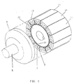
- FIG. 1 As an integral part of the sub-synchronous reluctance electrical machine is said rotor 20 which is in turn provided with a core of ferromagnetic plates having longitudinal teeth 21 uniformly arranged along the face thereof turned towards the stator 10, said teeth 21 being in a number different from the number of teeth 1 of stator 10.
- Figures 1-2 shown a sub-synchronous rotating motor the shell 3 of which fixedly houses a stator 10 within which a rotor 20 is arranged supported by shaft 5.
- the stator 10 is formed by a plurality of magnetically uncoupled or weakly coupled sectors 11, and is formed of ferromagnetic plates, the surface facing the rotor 20 being provided with a plurality of teeth 1.
- stator is provided with a series of grooves 2 within which the coils 6a, 6b, 6c, 6d, ... forming the winding 6 are arranged.
- rotor 20 formed of ferromagnetic plates, is provided with a plurality of teeth 21 on the surface thereof facing the stator 10, the number of teeth 21 of rotor 20 being different from the number of teeth 1 of stator 10.
- Figures 3-4 illustrate a motor similar to the one described above, differing therefrom only in that the stator 10 is internal and supported by shaft 5, whereas the rotor 20 is attached to the motor shell 3.
- Figures 5-6 illustrate in a very schematic manner a linear motor wherein the stator 10 and the rotor 20 face each other by means of respective teeth 1 and 21.
- the stator 10 in accordance with the invention is formed of uncoupled or weakly coupled sectors, and the coils 6a, 6a, 6c, 6d, ... are housed within each sector.
- Figures 7-8 in turn illustrate also in a schematic manner a sub-synchronous disc motor, wherein rotor 20 is attached to the motor shaft 5 and faces the stator 10 by means of the respective teeth 21 and 1.
- the stator 10 is formed of a plurality of uncoupled sectors 11, in this case illustrated by only two sectors 11, each provided with grooves to receive the coils of the winding 6. Said coils are maintained within each of the sectors 11 of stator 10, specifically inside the respective grooves 2.
- Figure 9 illustrate a sub-synchronous reluctance motor of two stators 10, 10' and two windings 6, 6'.
- said motor is formed of a first, external stator 10 attached to shell 3, which surrounds a rotor 20 attached to shaft 5, in a known manner.
- Said stator 10 is provided with a series of internal teeth 1 which face a series of external teeth 21 of rotor 20.
- Said rotor 20 is provided internally thereof with a second series of teeth 21' which face a series of teeth 1' of the second stator 10'.
- the stators 10,10' are fixed and have the respective sectors 11, 11' cooperating in an angular position, as are cooperating the respective windings 6, 6'.
- the machine is further provided with a monitoring device 4 for relative identification of the teeth of rotor 20 and the teeth of stator 10, as shown on Figure 10.
- Such device can be for example a resolver or an encoder, and is capable of determining the relative position between the teeth 1 of stator 10 and teeth 21 of rotor 20.
- this monitoring device 4 can be comprised, for example, of a position detector based on Hall effect, property attached to the stator.
- the speed of rotor 20 is a function of the number of teeth of said rotor 20 and a function of the triggering frequency of the power source (not illustrated), that is, in a more specific manner, the speed of rotor 20 is directly proportional to the triggering speed of the power source and inversely proportional to the number of teeth 21 of rotor 20. Accordingly, it can be concluded that with a proper selection of the number of teeth 21 of rotor 20 it is easy to obtain any rated rotation or speed. Any type of power source for the winding 6 of stator 10 can be used .
- said power source should have as a feature thereof the that it is controlled by the monitoring device 4 either directly or indirectly, thereby to feed the coils 6a, 6b, 6c, 6d, ... of sectors 11, according to the relative position between stator 10 and rotor 20.
- the monitoring device 4 in addition to the preferred types described above, use could be made of any device capable of accurately determining the relative position between stator 10 and rotor 20, and that may control a power source for the coils 6a, 6b, 6c, 6d, ..., either directly or through an interface.
- the internal position adopted for the winding 6 can also be modified, such as, for example, by arranging the coils thereof around the teeth 1 of stator 10. Another alternative is arranging the coils of the winding 6 around each of the sectors 11, thereby completely surrounding each said sector 11.
- each sector may comprise more than one coil, each fed separately by a respective power source.
Landscapes
- Engineering & Computer Science (AREA)
- Power Engineering (AREA)
- Synchronous Machinery (AREA)
- Linear Motors (AREA)
- Brushless Motors (AREA)
- Developing Agents For Electrophotography (AREA)
- Organic Insulating Materials (AREA)
Abstract
Description
- The present invention relates to a new reluctance electric machine and, more particularly, to a rotating or linear subsynchronous reluctance machine.
- As is known by those of skill in the art, one of the best known and most employed types of reluctance electrical machines is the switched reluctance motor, which presents, as a limiting aspect to the use thereof, the existence of torque and speed oscillations, as well as the difficulty of imposing high variation rates in the electric current.
- Other drawbacks of this switched reluctance motor relates to the fact that the circuits employed for controlling and feeding them are very complex and expensive, specially in respect of high-power machines.
- As an alternative to solve the above mentioned drawbacks, Brasilian patent application Pl9400880-9, published on 10/24/95 and relating to "Reluctance electrical machine" has been proposed, which provided an electrical machine comprised of a rotor and a stator. Said stator was provided with a core comprised of magnetic plates and provided with longitudinal teeth projecting towards the rotor. Said stator also comprised a plurality of grooves capable of receiving a multi-phase winding, said winding being comprised of a plurality of coils homogeneously surrounding the stator's magnetic material. As a supplementation, said rotor was formed by a core of magnetic plates provided with longitudinal teeth projecting towards the stator. Thus, upon energizing of said coils by a balanced multiphase voltage, a rotating field was generated, which caused a relative movement between rotor and stator.
- However, and even though such machine was capable of overcoming the drawbacks of the prior art, there is still the fact that the electrical machine described in Brasilian patent application Pl 9400880-9 has the particular drawback of a low power factor, and in some cases may increase the cost of the drive system.
- From FR-A-2.573.586 an electrical motor with variable reluctance and electronic commutation is known, comprising a stator ring containing contacts provided with coils, the number of which is a multiple of the product of the number of commutators times the number 4 (pattern 4), and a rotor ring containing teeth, the number of which is the same multiple of a prime number greater than the product "commutators x pattern 4", the rings being produced by stacking metal sheets cut out respectively as sectors of 2 to 5 teeth and as sectors of 2 to 5 contacts; the residual air gaps formed by the side-by-side placement of the said sectors are located substantially in the median part of the contacts and of the teeth respectively. This characteristic makes it possible to eradicate the parasitic reluctance due to the assembly of metal sheets cut out sectorially in the rings.
- US-A-4,995,159 discloses a motor structure and energization scheme providing a high efficiency electronically commutated reluctance motor that is characterized by less iron losses than conventional switched reluctance motors. The motor operates without the reversal of the flow of flux in the stator. Also, the flux switching frequency in the stator is minimized. By eliminating flux reversals and minimizing the flux switching frequency, the electronically commutated reluctance motor is operable over a wide range of speeds with improved efficiency. Structurally, the stator includes unevenly spaced poles which are grouped into pairs separated by a space related to the even spacing of the poles on the rotor. Adjacent pairs of poles on the stator are separated by a spacing which is not equal to the spacing between the poles of a pair. To provide for rotation of the rotor, each pair of poles on the stator is polarized to form poles of opposite polarity such that a magnetic circuit joins the two adjacent poles of the pair. Magnetic circuits linking different pairs of stator poles, which are the source flux reversals and high switching frequencies in conventional motors, are prevented by providing a stator construction that is without low reluctance paths between adjacent pairs of stator poles.
- It is an object of the present invention to provide a reluctance electrical machine providing high torque at low speeds, advantageously replacing the switched reluctance, conventional electrical machines.
- It is an object of the present invention to provide a reluctance electrical machine presenting high torques at low speeds, advantageously replacing in terms of cost and maintenance the conventional mechanical reduction machines that multiply the torque and decrease the speed.
- It is an object of the present invention to provide a reluctance electrical machine that allows a large control of the rotation and torque thereof, without the need of a complex and expensive power and control circuit.
- Another object of the present invention is to provide a reluctance electrical machine that, by reason of its constructive features, does not present oscillations in the resulting torque and speed.
- Another object of the present invention is to provide an improvement on the reluctance electrical machine as per the above referenced Brasilian patent application PI 9400880-9, having characteristics of a high power factor.
- These and other objects and advantages of the present invention are achieved by a method for operating a sub-synchronous reluctance electrical machine as set forth in
Claim 1 and by a sub-synchronous reluctance electrical machine as set forth inClaim 2. - The number of teeth on the rotor is necessarily different from the number of teeth on the stator.
- The machine is provided with a device for monitoring and identifying the relative position between the stator and rotor teeth in order to allow the identification of the region of largest magnetic permeability between the rotor and the stator, in order to allow the proper feeding of the stator coils, thereby obtaining the maximum possible torque.
- The present invention has constructive characteristics similar to those of the machine described on Brasilian patent application Pl9400880-9, however it is fundamentally different therefrom in the following items:
- The stator core is comprised of magnetically uncoupled or weakly coupled sectors, contrary to the machine described on the document Pl9400880-9, which employs integral magnetic plates; and
- The coils are individually fed with currents controlled and monitored by devices identifying the relative position between the stator and rotor teeth, whereas on the document Pl9400880-9 the coils are multiphase and are energized by balanced multiphase voltages.
- These differences allow the machine subject matter of the present invention to possess a high power factor, which means that during the operation thereof the machine absorbs low currents.
- In summary, the present invention provides a sub-synchronous reluctance electrical machine of the type comprising at least one rotor formed of ferromagnetic plates and provided with a plurality of uniformly distributed teeth and at least a stator provided on the surface thereof facing said rotor with a second plurality of teeth, also uniformly arranged, plus coils, said coils being selectively fed by a current power source, and the at least one stator is formed by a series of magnetically uncoupled or weakly coupled sectors of ferromagnetic plates, each sector comprising one coil, the coil of each sector having the power thereof controlled by a monitoring device, and the number of teeth on the stator being different from the number of teeth on the rotor.
- The scope of the present invention will be best understood in the light of the following description, made with reference to the appended drawings, shown for illustrative purposes only and not as limitation of the scope of the invention, wherein:
- Figure 1 is a perspective view in partial section of a sub-synchronous reluctance rotating motor made according to an embodiment of the invention
- Figure 2 is a section view of the motor shown on Figure 1;
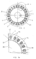
- Figure 2a is an enlarged detailed view of the section of the motor on Figure 2;
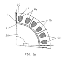
- Figure 2b is a view similar to Figure 2a, but with the rotor displaced 1/6th from the pitch of the stator teeth;
- Figure 3 is a perspective view in partial section of a sub-synchronous reluctance rotating motor identical to the one shown on Figure 1, but with the stator internal to the rotor;
- Figure 4 is a section view of the motor shown on Figure 3;
- Figure 4a is a detailed view of a part of Figure 4;
- Figure 5 is a schematic, perspective representation of a sub-synchronous reluctance linear motor made according to an embodiment of the invention;
- Figure 6 is a longitudinal section view of the motor shown on Figure 5;
- Figure 7 is a perspective view of a sub-synchronous reluctance disc motor made according to an embodiment of the invention;
- Figure 8 is a cross-section view of the motor on Figure 7;
- Figure 9 is a perspective, partial section view of a motor with two stators and two (inner and outer) sub-synchronous reluctance windings made according to an embodiment of the invention;
- Figure 10 is an elevation view of the shaft end of any of the motors illustrated above, to which is coupled a device for monitoring and identifying the relative position between the rotor and stator teeth; and
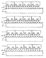
- Figures 11-11c illustrate in a schematic manner the movement of a linear motor of the type shown on Figure 5.
- In accordance with the above Figures, the reluctance electrical machine of the present invention is conceptually defined by a
stator 10 provided with a core comprised of magnetically uncoupled or weakly coupledferromagnetic plate sectors 11 havinglongitudinal teeth 1 arranged on the face thereof turned towards therotor 20 and provided withgrooves 2 for housing one ormore windings 6, 6'.
Thesewindings 6, 6' are composed of a plurality ofcoils 6a, 6b, 6c, 6d, ... surrounding the magnetic material ofstator 10, in order to generate a magnetic field whenever this winding is energized.
As an integral part of the sub-synchronous reluctance electrical machine is saidrotor 20 which is in turn provided with a core of ferromagnetic plates havinglongitudinal teeth 21 uniformly arranged along the face thereof turned towards thestator 10, saidteeth 21 being in a number different from the number ofteeth 1 ofstator 10.
More specifically, Figures 1-2 shown a sub-synchronous rotating motor theshell 3 of which fixedly houses astator 10 within which arotor 20 is arranged supported byshaft 5.
As shown, thestator 10 is formed by a plurality of magnetically uncoupled or weakly coupledsectors 11, and is formed of ferromagnetic plates, the surface facing therotor 20 being provided with a plurality ofteeth 1. In addition, said stator is provided with a series ofgrooves 2 within which thecoils 6a, 6b, 6c, 6d, ... forming the winding 6 are arranged.
In a supplementary manner,rotor 20, formed of ferromagnetic plates, is provided with a plurality ofteeth 21 on the surface thereof facing thestator 10, the number ofteeth 21 ofrotor 20 being different from the number ofteeth 1 ofstator 10.
Figures 3-4 illustrate a motor similar to the one described above, differing therefrom only in that thestator 10 is internal and supported byshaft 5, whereas therotor 20 is attached to themotor shell 3.
Figures 5-6 illustrate in a very schematic manner a linear motor wherein thestator 10 and therotor 20 face each other by means ofrespective teeth stator 10 in accordance with the invention is formed of uncoupled or weakly coupled sectors, and the coils 6a, 6a, 6c, 6d, ... are housed within each sector.
Figures 7-8 in turn illustrate also in a schematic manner a sub-synchronous disc motor, whereinrotor 20 is attached to themotor shaft 5 and faces thestator 10 by means of therespective teeth stator 10 is formed of a plurality ofuncoupled sectors 11, in this case illustrated by only twosectors 11, each provided with grooves to receive the coils of the winding 6. Said coils are maintained within each of thesectors 11 ofstator 10, specifically inside therespective grooves 2.
Finally, Figure 9 illustrate a sub-synchronous reluctance motor of twostators 10, 10' and twowindings 6, 6'.
More particularly, said motor is formed of a first,external stator 10 attached toshell 3, which surrounds arotor 20 attached toshaft 5, in a known manner. Saidstator 10 is provided with a series ofinternal teeth 1 which face a series ofexternal teeth 21 ofrotor 20. Saidrotor 20 is provided internally thereof with a second series of teeth 21' which face a series of teeth 1' of the second stator 10'. In this case, thestators 10,10' are fixed and have therespective sectors 11, 11' cooperating in an angular position, as are cooperating therespective windings 6, 6'.
The machine is further provided with a monitoring device 4 for relative identification of the teeth ofrotor 20 and the teeth ofstator 10, as shown on Figure 10. Such device, of a known type, can be for example a resolver or an encoder, and is capable of determining the relative position between theteeth 1 ofstator 10 andteeth 21 ofrotor 20.
Alternatively, this monitoring device 4 can be comprised, for example, of a position detector based on Hall effect, property attached to the stator.
For a better understanding of the inventive concept now claimed, the operation of the sub-synchronous reluctance electrical machine will be described in a more detailed manner, taking as reference the linear sub-synchronous motor shown on Figure 5.
By means of the monitoring device 4 for identification of the relative position ofteeth 1 ofstator 10 andteeth 21 ofrotor 20, the condition indicated on Figure 11 (teeth 1a and 21a aligned) is identified and thecoils 6a and 6b are energized, that is, the magnetic field is always maintained at 90° magnetic degrees from the region of highest permeability, thereby causing a displacement ofteeth 21 ofrotor 20, until they reach an equilibrium position shown on Figure 11a. In this condition, wherein the stator teeth tooth 1e can be seen in alignment with rotor tooth 21e, the coil 6a is de-energized and the subsequent coil 6c is energized, jointly withcoil 6b, thereby causing a new displacement ofrotor teeth 21 towards the position shown on Figure 11b, where tooth 1I is seen aligned with tooth 21I. In the same sequence,coil 6b is de-energized, and coils 6c and 6d are energized, thereby obtaining a displacement ofrotor 20 towards the position shown on Figure 11c, where tooth 1N is seen aligned with tooth 21N, and so on and so forth.
Accordingly, by successively repeating in a controlled manner the operation of energizing and de-energizing the coils, a controlled movement ofrotor 20 is obtained. As shown on Figure 11, when thecoils 6a and 6b ofstator 10 are energized, the region of highest permeability betweenstator 10 androtor 20 tends to stay in alignment with the field, so that the latter drags with it said region of highest permeability, thereby causing the relative displacement betweenrotor 20 andstator 10.
While the coils are successively energized and de-energized, the sequence of movements betweenrotor 20 andstator 10 takes place, so that, upon completion of 360 electrical degrees of field displacement, therotor 20 will have traversed only two teeth ofstator 10.
In the event that the field is placed out of phase by 90° in the opposite direction, an operation in the four quadrants can be obtained, that is, an acceleration or braking torque can be obtained in either of the machine's directions of rotation (clockwise or counterclockwise).
The proper combination of the number ofteeth 1 ofstator 10 with the number ofteeth 21 ofrotor 20 allows the achievement of torque and determination of the synchronous speed of the sub-synchronous reluctance electrical machine. As already said, the number of teeth ofrotor 20 should differ from the number ofteeth 1 ofstator 10. By way of example, the practical construction illustrated on Figure 1 shows a stator with 144 teeth and a rotor with 146 teeth.
The speed ofrotor 20 is a function of the number of teeth of saidrotor 20 and a function of the triggering frequency of the power source (not illustrated), that is, in a more specific manner, the speed ofrotor 20 is directly proportional to the triggering speed of the power source and inversely proportional to the number ofteeth 21 ofrotor 20. Accordingly, it can be concluded that with a proper selection of the number ofteeth 21 ofrotor 20 it is easy to obtain any rated rotation or speed.
Any type of power source for the winding 6 ofstator 10 can be used.
In particular, said power source (not illustrated) should have as a feature thereof the that it is controlled by the monitoring device 4 either directly or indirectly, thereby to feed thecoils 6a, 6b, 6c, 6d, ... ofsectors 11, according to the relative position betweenstator 10 androtor 20.
In respect of the monitoring device 4, in addition to the preferred types described above, use could be made of any device capable of accurately determining the relative position betweenstator 10 androtor 20, and that may control a power source for thecoils 6a, 6b, 6c, 6d, ..., either directly or through an interface.
On the other hand, the internal position adopted for the winding 6 can also be modified, such as, for example, by arranging the coils thereof around theteeth 1 ofstator 10. Another alternative is arranging the coils of the winding 6 around each of thesectors 11, thereby completely surrounding each saidsector 11. In addition, each sector may comprise more than one coil, each fed separately by a respective power source.
Claims (8)
- A method for operating a sub-synchronous reluctance electrical machine comprising at least one rotor (20) and at least one stator (10) having a winding (6) formed by a plurality of coils (6a, 6b, 6c), wherein:the method being characterized by the step of tracking a relative position of said rotor (20) with respect to said stator (10) and sequentially energizing said coils (6a, 6b, 6c) according to the following operating phases:said rotor (20) is formed from ferromagnetic plates and is provided with a plurality of longitudinal rotor teeth (21A, 21B, 21E) uniformly distributed over a rotor surface facing said stator (10), said rotor teeth (21A, 21B, 21E) projecting towards said stator (10),said stator (10) is formed from a series of magnetic uncoupled or weakly coupled stator sectors (11) arranged side by side and made of ferromagnetic plates, each stator sector (11) being provided with a plurality of longitudinal stator teeth (1A, 1E, 1I) uniformly distributed over a stator surface facing said rotor (20), said stator teeth (1A, 1E, 1I) projecting towards said rotor teeth (21A, 21B, 21E),each stator sector (11) being provided with a coil of said plurality of coils (6a, 6b, 6c), said coil being arranged so as to surround ferromagnetic material of the respective stator sector (11), for creating a magnetic field when said coil is energized via a current power source, andthe total number of stator teeth (1A, 1E, 1I) is different from the number of rotor teeth (21A, 21B, 21E);a) identifying a high permeability region between a stator tooth (1A) of a first stator sector (11) and a first rotor tooth (21A), which high permeability region exists if said stator tooth (1A) is aligned with said rotor tooth (21A), energizing a first coil (6a) of a first stator sector (11) together with a second coil (6b) of a second stator sector (11), said second stator sector (11) being adjacent to said first stator sector (11) in the direction opposite to the direction of movement of said rotor (20), the energizing condition of said first and second coils (6a, 6b) causing displacement of said rotor (20) with respect to said stator (10);b) identifying a high permeability region between a stator tooth (1E) of the second stator sector (11) and a second rotor tooth (21E), which high permeability region exists if said stator tooth (1 E) is aligned with said rotor tooth (21 E);
de-energizing said first coil (6a),
maintaining energized said second coil (6b),
energizing a third coil (6c) of a third stator sector (11), said third stator sector (11) being adjacent to said second sector (11) in the direction opposite to the direction of movement of said rotor (20), the energizing condition of said second and third coils (6b, 6c) causing further displacement of said rotor (20) with respect to said stator (10); andc) selectively energizing and de-energizing coils (6a, 6b, 6c) of any stator sector (11) as per operating phase b), in order to always maintain energized coils (6a, 6b, 6c) of two adjacent stator sectors (11) for producing a sequence of movements of said rotor (20) with respect to said stator (10). - A sub-synchronous reluctance electrical machine comprising at least one rotor (20) and at least one stator (10) having a winding (6) formed by a plurality of coils (6a, 6b, 6c), wherein:characterized in that it comprises a monitoring device (4) operative for tracking a relative position of said rotor (20) with respect to said stator (10) and sequentially energizing said coils (6a, 6b, 6c) according to the following operating phases:said rotor (20) is formed from ferromagnetic plates and is provided with a plurality of longitudinal rotor teeth (21A, 21B, 21E) uniformly distributed over a rotor surface facing said stator (10), said rotor teeth (21A, 21B, 21E) projecting towards said stator (10),said stator (10) is formed from a series of magnetic uncoupled or weakly coupled stator sectors (11) arranged side by side and made of ferromagnetic plates, each stator sector (11) being provided with a plurality of longitudinal stator teeth (1A, 1E, 1I)uniformly distributed over a stator surface facing said rotor (20), said stator teeth (1A, 1E, 1I) projecting towards said rotor teeth (21A, 21B, 21E),each stator sector (11) being provided with a coil of said plurality of coils (6a, 6b, 6c), said coil being arranged so as to surround ferromagnetic material of the respective stator sector (11), for creating a magnetic field when said coil is energized via a current power source, andthe total number of stator teeth (1A, 1E, 1I) is different from the number of rotor teeth (21A, 21B, 21E);a) identifying a high permeability region between a stator tooth (1A) of a first stator sector (11) and a first rotor tooth (21A), which high permeability region exists if said stator tooth (1A) is aligned with said rotor tooth (21A),
energizing a first coil (6a) of a first stator sector (11) together with a second coil (6b) of a second stator sector (11), said second stator sector (11) being adjacent to said first stator sector (11) in the direction opposite to the direction of movement of said rotor (20), the energizing condition of said first and second coils (6a, 6b) causing displacement of said rotor (20) with respect to said stator (10);b) identifying a high permeability region between a stator tooth (1E) of the second stator sector (11) and a second rotor tooth (21E), w hich h igh permeability region exists if said stator tooth (1E) is aligned with said rotor tooth (21E),
de-energizing said first coil (6a),
maintaining energized said second coil (6b),
energizing a third coil (6c) of a third stator sector (11), said third stator sector (11) being adjacent to said second sector (11) in the direction opposite to the direction of movement of said rotor (20), the energized condition of said second and third coils (6b, 6c) causing further displacement of said rotor (20) with respect to said stator (10); andc) selectively energizing and de-energizing coils (6a, 6b, 6c) of any stator sector (11) as per operating phase b), in order to always maintain energized coils (6a, 6b, 6c) of two adjacent stator sectors (11) for producing a sequence of movements of said rotor (20) with respect to said stator (10). - Machine in accordance with claim 2, characterized in that each coil (6a, 6b, 6c) is arranged in at least two grooves (2) of the respective sector (11) of said stator (10).
- Machine in accordance with claim 2, characterized in that said monitoring device (4) is a Hall-type detector.
- Machine in accordance of claim 2, characterized in that said monitoring device (4) is an encoder or a resolver.
- Machine in accordance with claim 2, characterized in that it is a sub-synchronous reluctance rotating motor.
- Machine in accordance with claim 2, characterized in that it is a sub-synchronous reluctance linear motor.
- Machine in accordance with claim 2, characterized in that it is a sub-synchronous reluctance disc motor.
Applications Claiming Priority (5)
| Application Number | Priority Date | Filing Date | Title |
|---|---|---|---|
| BR9804426-5A BR9804426A (en) | 1998-10-16 | 1998-10-16 | Electric machine of subsynchronous reluctance. |
| BR9804426 | 1998-10-16 | ||
| JP2000008195A JP2001204162A (en) | 1998-10-16 | 2000-01-17 | Subsynchronous reluctance electrical machine |
| CA002297337A CA2297337C (en) | 1998-10-16 | 2000-01-27 | Subsynchronous reluctance electrical machine |
| CN00100707A CN1307394A (en) | 1998-10-16 | 2000-02-01 | Subsynchronous reluctance motor |
Publications (3)
| Publication Number | Publication Date |
|---|---|
| EP0994555A2 EP0994555A2 (en) | 2000-04-19 |
| EP0994555A3 EP0994555A3 (en) | 2001-05-16 |
| EP0994555B1 true EP0994555B1 (en) | 2004-05-26 |
Family
ID=27425285
Family Applications (1)
| Application Number | Title | Priority Date | Filing Date |
|---|---|---|---|
| EP99119802A Expired - Lifetime EP0994555B1 (en) | 1998-10-16 | 1999-10-06 | Subsynchronous reluctance electrical machine |
Country Status (11)
| Country | Link |
|---|---|
| US (1) | US6239530B1 (en) |
| EP (1) | EP0994555B1 (en) |
| JP (2) | JP2000152579A (en) |
| KR (1) | KR100633706B1 (en) |
| CN (1) | CN1307394A (en) |
| AT (1) | ATE268068T1 (en) |
| BR (1) | BR9804426A (en) |
| CA (1) | CA2297337C (en) |
| DE (1) | DE69917557T2 (en) |
| ES (1) | ES2222648T3 (en) |
| PT (1) | PT994555E (en) |
Families Citing this family (26)
| Publication number | Priority date | Publication date | Assignee | Title |
|---|---|---|---|---|
| FR2806951B1 (en) * | 2000-03-31 | 2002-06-14 | Aro | ELECTRIC MOTORIZING DEVICE FOR TOOLS |
| US6648252B2 (en) * | 2000-10-04 | 2003-11-18 | Emerson Electric Co. | Switched reluctance machine and food waste disposer employing switched reluctance machine |
| US6854673B2 (en) * | 2000-11-28 | 2005-02-15 | Emerson Electric Co. | Food waste disposer having a variable speed motor |
| US6481652B2 (en) | 2000-11-28 | 2002-11-19 | Emerson Electric Co. | Food waste disposer having variable speed motor and methods of operating same |
| US20020093269A1 (en) * | 2001-01-16 | 2002-07-18 | Harter Bernard G. | Slot area undercut for segmented stators |
| US6744166B2 (en) * | 2001-01-04 | 2004-06-01 | Emerson Electric Co. | End cap assembly for a switched reluctance electric machine |
| US6700284B2 (en) * | 2001-03-26 | 2004-03-02 | Emerson Electric Co. | Fan assembly including a segmented stator switched reluctance fan motor |
| US6584813B2 (en) | 2001-03-26 | 2003-07-01 | Emerson Electric Co. | Washing machine including a segmented stator switched reluctance motor |
| US7012350B2 (en) * | 2001-01-04 | 2006-03-14 | Emerson Electric Co. | Segmented stator switched reluctance machine |
| US6897591B2 (en) * | 2001-03-26 | 2005-05-24 | Emerson Electric Co. | Sensorless switched reluctance electric machine with segmented stator |
| GB0209794D0 (en) * | 2002-04-30 | 2002-06-05 | Univ Newcastle | Switched reluctance electrical machine |
| DE102006005046A1 (en) * | 2006-02-03 | 2007-08-09 | Siemens Ag | Electric machine with uneven pole teeth |
| WO2009018149A1 (en) * | 2007-07-27 | 2009-02-05 | The Texas A & M University System | Short-flux path motors / generators |
| CN106067717A (en) * | 2007-12-21 | 2016-11-02 | 张玉宝 | A kind of method improving motor effective power |
| US7851966B2 (en) * | 2008-01-10 | 2010-12-14 | Rippel Wally E | Stator for electric machine with improved efficiency and thermal performance |
| JP4747184B2 (en) * | 2008-04-14 | 2011-08-17 | 本田技研工業株式会社 | Electric motor |
| JP4505524B2 (en) * | 2008-07-22 | 2010-07-21 | 本田技研工業株式会社 | Power equipment |
| WO2010024793A1 (en) * | 2008-08-29 | 2010-03-04 | Moog Inc. | Permanent magnet-type stepping motors |
| JP5653997B2 (en) * | 2009-09-08 | 2015-01-14 | ムーグ インコーポレーテッド | Stepping motor with short step interval |
| FR2961970B1 (en) * | 2010-06-25 | 2017-03-10 | Valeo Systemes De Controle Moteur | ELECTRICAL MOTOR WITH ALTERNATING CURRENT OF A COMBINED POWER SUPPLY AND CHARGING ELECTRICAL DEVICE |
| DE102012103677A1 (en) * | 2012-04-26 | 2013-10-31 | Feaam Gmbh | Electric machine |
| RU2543522C2 (en) * | 2013-07-23 | 2015-03-10 | Общество с ограниченной ответственностью "Механотроника" | Mechatronic device |
| US11255612B2 (en) | 2014-07-25 | 2022-02-22 | Enure, Inc. | Wound strip machine |
| US10756583B2 (en) | 2014-07-25 | 2020-08-25 | Enure, Inc. | Wound strip machine |
| WO2016014849A1 (en) | 2014-07-25 | 2016-01-28 | Prippel Technologies, Llc | Fluid-cooled wound strip structure |
| DE102017105977A1 (en) * | 2017-03-21 | 2018-09-27 | Schaeffler Technologies AG & Co. KG | Dynamoelectric machine with reduced cogging torque |
Family Cites Families (14)
| Publication number | Priority date | Publication date | Assignee | Title |
|---|---|---|---|---|
| US4315171A (en) * | 1977-05-23 | 1982-02-09 | Ernest Schaeffer | Step motors |
| US4198582A (en) * | 1977-06-24 | 1980-04-15 | Exxon Research & Engineering Co. | High performance stepper motor |
| US4475051A (en) * | 1982-08-27 | 1984-10-02 | International Business Machines Corporation | Low inertia high torque variable reluctance motor |
| FR2573586B1 (en) * | 1984-11-19 | 1988-08-05 | Jarret Tech Electr | IMPROVEMENTS ON VARIABLE RELUCTANCE MOTORS |
| US5173651A (en) * | 1985-06-28 | 1992-12-22 | Kollmorgen Technologies Corporation | Electrical drive systems |
| US4713570A (en) * | 1986-06-04 | 1987-12-15 | Pacific Scientific Co. | Magnetically enhanced variable reluctance motor systems |
| US4733117A (en) * | 1987-04-27 | 1988-03-22 | The Superior Electric Company | Reluctance synchro/resolver |
| US4990809A (en) * | 1987-04-27 | 1991-02-05 | The Superior Electric Company | Variable reluctance motor |
| US4995159A (en) * | 1988-08-15 | 1991-02-26 | Pacific Scientific Company | Method of making an electronically commutated reluctance motor |
| JP2599061B2 (en) * | 1991-12-13 | 1997-04-09 | オリエンタルモーター株式会社 | Stepping motor |
| IT1262572B (en) * | 1993-11-03 | 1996-07-04 | Alessandro Dreoni | LINEAR OR ROTARY SYNCHRONOUS ELECTRIC MOTOR WITH VARIABLE RELUCTANCE AND VOLUMETRIC FORCE DEVELOPMENT |
| US6025668A (en) * | 1995-12-08 | 2000-02-15 | Dana Corporation | Variable reluctance motor having bifurcated stator poles |
| DE19743380C1 (en) * | 1997-09-30 | 1999-03-25 | Emf 97 Gmbh | Energy conversion reluctance motor |
| US6051898A (en) * | 1998-01-02 | 2000-04-18 | Japan Servo Co., Ltd. | Stepping motor having external rotor and electromagnetic-combined-permanent-magnet stator |
-
1998
- 1998-10-16 BR BR9804426-5A patent/BR9804426A/en not_active Application Discontinuation
-
1999
- 1999-09-29 US US09/408,298 patent/US6239530B1/en not_active Expired - Lifetime
- 1999-10-06 EP EP99119802A patent/EP0994555B1/en not_active Expired - Lifetime
- 1999-10-06 AT AT99119802T patent/ATE268068T1/en not_active IP Right Cessation
- 1999-10-06 ES ES99119802T patent/ES2222648T3/en not_active Expired - Lifetime
- 1999-10-06 PT PT99119802T patent/PT994555E/en unknown
- 1999-10-06 DE DE69917557T patent/DE69917557T2/en not_active Expired - Lifetime
- 1999-10-12 KR KR1019990044156A patent/KR100633706B1/en not_active IP Right Cessation
- 1999-10-18 JP JP11295559A patent/JP2000152579A/en active Pending
-
2000
- 2000-01-17 JP JP2000008195A patent/JP2001204162A/en active Pending
- 2000-01-27 CA CA002297337A patent/CA2297337C/en not_active Expired - Fee Related
- 2000-02-01 CN CN00100707A patent/CN1307394A/en active Pending
Also Published As
| Publication number | Publication date |
|---|---|
| PT994555E (en) | 2004-10-29 |
| US6239530B1 (en) | 2001-05-29 |
| EP0994555A2 (en) | 2000-04-19 |
| CA2297337C (en) | 2008-04-08 |
| DE69917557D1 (en) | 2004-07-01 |
| EP0994555A3 (en) | 2001-05-16 |
| KR100633706B1 (en) | 2006-10-13 |
| JP2001204162A (en) | 2001-07-27 |
| DE69917557T2 (en) | 2005-07-14 |
| KR20000029016A (en) | 2000-05-25 |
| CN1307394A (en) | 2001-08-08 |
| ATE268068T1 (en) | 2004-06-15 |
| CA2297337A1 (en) | 2001-07-27 |
| JP2000152579A (en) | 2000-05-30 |
| ES2222648T3 (en) | 2005-02-01 |
| BR9804426A (en) | 2000-05-16 |
Similar Documents
| Publication | Publication Date | Title |
|---|---|---|
| EP0994555B1 (en) | Subsynchronous reluctance electrical machine | |
| JP5318758B2 (en) | Ring coil motor | |
| US4719378A (en) | Brushless motor having permanent magnet rotor and salient pole stator | |
| US4197488A (en) | Electrical machine | |
| US4990809A (en) | Variable reluctance motor | |
| US4995159A (en) | Method of making an electronically commutated reluctance motor | |
| EP0559818B1 (en) | Polyphase switched reluctance motor | |
| US4237396A (en) | Electromagnetic machines with permanent magnet excitation | |
| US6683397B2 (en) | Electric machine having at least one magnetic field detector | |
| KR101228013B1 (en) | Dc motor with asymmetrical poles | |
| JP3693100B2 (en) | Multiphase traverse flux machine | |
| JPS6341307B2 (en) | ||
| US4823039A (en) | Electrical machines | |
| EP0465462A4 (en) | Electronically commutated reluctance motor | |
| US20130057105A1 (en) | Permanent magnet motors and methods of assembling the same | |
| EP0848482A2 (en) | Brushless DC motors | |
| US8373328B2 (en) | Pulsed multi-rotor constant air gap switched reluctance motor | |
| KR100337665B1 (en) | Permanent Magnet Motor | |
| EP0735652A1 (en) | Improvements in switched reluctance machines | |
| WO2022020226A1 (en) | Variable reluctance step motor having enhanced holding torque | |
| US5438227A (en) | Linear pulse motor | |
| JP4248778B2 (en) | Permanent magnet motor rotor | |
| US4608505A (en) | Commutatorless d.c. electric motor | |
| KR0121122B1 (en) | Linear magnetic reluctance motor | |
| US20130057104A1 (en) | Permanent magnet motors and methods of assembling the same |
Legal Events
| Date | Code | Title | Description |
|---|---|---|---|
| PUAI | Public reference made under article 153(3) epc to a published international application that has entered the european phase |
Free format text: ORIGINAL CODE: 0009012 |
|
| AK | Designated contracting states |
Kind code of ref document: A2 Designated state(s): AT BE CH CY DE DK ES FI FR GB GR IE IT LI LU MC NL PT SE |
|
| AX | Request for extension of the european patent |
Free format text: AL;LT;LV;MK;RO;SI |
|
| PUAL | Search report despatched |
Free format text: ORIGINAL CODE: 0009013 |
|
| AK | Designated contracting states |
Kind code of ref document: A3 Designated state(s): AT BE CH CY DE DK ES FI FR GB GR IE IT LI LU MC NL PT SE |
|
| AX | Request for extension of the european patent |
Free format text: AL;LT;LV;MK;RO;SI |
|
| 17P | Request for examination filed |
Effective date: 20010920 |
|
| 17Q | First examination report despatched |
Effective date: 20011109 |
|
| AKX | Designation fees paid |
Free format text: AT BE CH CY DE DK ES FI FR GB GR IE IT LI LU MC NL PT SE |
|
| GRAH | Despatch of communication of intention to grant a patent |
Free format text: ORIGINAL CODE: EPIDOS IGRA |
|
| RAP1 | Party data changed (applicant data changed or rights of an application transferred) |
Owner name: INVENTIO AG |
|
| GRAS | Grant fee paid |
Free format text: ORIGINAL CODE: EPIDOSNIGR3 |
|
| GRAA | (expected) grant |
Free format text: ORIGINAL CODE: 0009210 |
|
| AK | Designated contracting states |
Kind code of ref document: B1 Designated state(s): AT BE CH CY DE DK ES FI FR GB GR IE IT LI LU MC NL PT SE |
|
| PG25 | Lapsed in a contracting state [announced via postgrant information from national office to epo] |
Ref country code: CY Free format text: LAPSE BECAUSE OF FAILURE TO SUBMIT A TRANSLATION OF THE DESCRIPTION OR TO PAY THE FEE WITHIN THE PRESCRIBED TIME-LIMIT Effective date: 20040526 |
|
| REG | Reference to a national code |
Ref country code: GB Ref legal event code: FG4D |
|
| REG | Reference to a national code |
Ref country code: CH Ref legal event code: EP |
|
| REG | Reference to a national code |
Ref country code: IE Ref legal event code: FG4D |
|
| REF | Corresponds to: |
Ref document number: 69917557 Country of ref document: DE Date of ref document: 20040701 Kind code of ref document: P |
|
| PG25 | Lapsed in a contracting state [announced via postgrant information from national office to epo] |
Ref country code: GR Free format text: LAPSE BECAUSE OF FAILURE TO SUBMIT A TRANSLATION OF THE DESCRIPTION OR TO PAY THE FEE WITHIN THE PRESCRIBED TIME-LIMIT Effective date: 20040826 Ref country code: DK Free format text: LAPSE BECAUSE OF FAILURE TO SUBMIT A TRANSLATION OF THE DESCRIPTION OR TO PAY THE FEE WITHIN THE PRESCRIBED TIME-LIMIT Effective date: 20040826 |
|
| REG | Reference to a national code |
Ref country code: SE Ref legal event code: TRGR |
|
| PG25 | Lapsed in a contracting state [announced via postgrant information from national office to epo] |
Ref country code: LU Free format text: LAPSE BECAUSE OF NON-PAYMENT OF DUE FEES Effective date: 20041006 Ref country code: IE Free format text: LAPSE BECAUSE OF NON-PAYMENT OF DUE FEES Effective date: 20041006 |
|
| REG | Reference to a national code |
Ref country code: PT Ref legal event code: SC4A Free format text: AVAILABILITY OF NATIONAL TRANSLATION Effective date: 20040820 |
|
| PG25 | Lapsed in a contracting state [announced via postgrant information from national office to epo] |
Ref country code: MC Free format text: LAPSE BECAUSE OF NON-PAYMENT OF DUE FEES Effective date: 20041031 |
|
| ET | Fr: translation filed | ||
| REG | Reference to a national code |
Ref country code: ES Ref legal event code: FG2A Ref document number: 2222648 Country of ref document: ES Kind code of ref document: T3 |
|
| PLBE | No opposition filed within time limit |
Free format text: ORIGINAL CODE: 0009261 |
|
| STAA | Information on the status of an ep patent application or granted ep patent |
Free format text: STATUS: NO OPPOSITION FILED WITHIN TIME LIMIT |
|
| 26N | No opposition filed |
Effective date: 20050301 |
|
| REG | Reference to a national code |
Ref country code: IE Ref legal event code: MM4A |
|
| PGFP | Annual fee paid to national office [announced via postgrant information from national office to epo] |
Ref country code: NL Payment date: 20071016 Year of fee payment: 9 Ref country code: ES Payment date: 20071030 Year of fee payment: 9 |
|
| PGFP | Annual fee paid to national office [announced via postgrant information from national office to epo] |
Ref country code: AT Payment date: 20071015 Year of fee payment: 9 Ref country code: FI Payment date: 20071015 Year of fee payment: 9 Ref country code: IT Payment date: 20071024 Year of fee payment: 9 |
|
| PGFP | Annual fee paid to national office [announced via postgrant information from national office to epo] |
Ref country code: BE Payment date: 20071123 Year of fee payment: 9 Ref country code: SE Payment date: 20071012 Year of fee payment: 9 |
|
| PGFP | Annual fee paid to national office [announced via postgrant information from national office to epo] |
Ref country code: GB Payment date: 20071023 Year of fee payment: 9 Ref country code: CH Payment date: 20080117 Year of fee payment: 9 |
|
| REG | Reference to a national code |
Ref country code: PT Ref legal event code: MM4A Free format text: LAPSE DUE TO NON-PAYMENT OF FEES Effective date: 20090406 |
|
| BERE | Be: lapsed |
Owner name: *INVENTIO A.G. Effective date: 20081031 |
|
| REG | Reference to a national code |
Ref country code: CH Ref legal event code: PL |
|
| EUG | Se: european patent has lapsed | ||
| GBPC | Gb: european patent ceased through non-payment of renewal fee |
Effective date: 20081006 |
|
| NLV4 | Nl: lapsed or anulled due to non-payment of the annual fee |
Effective date: 20090501 |
|
| PG25 | Lapsed in a contracting state [announced via postgrant information from national office to epo] |
Ref country code: NL Free format text: LAPSE BECAUSE OF NON-PAYMENT OF DUE FEES Effective date: 20090501 Ref country code: FI Free format text: LAPSE BECAUSE OF NON-PAYMENT OF DUE FEES Effective date: 20081006 |
|
| PG25 | Lapsed in a contracting state [announced via postgrant information from national office to epo] |
Ref country code: PT Free format text: LAPSE BECAUSE OF NON-PAYMENT OF DUE FEES Effective date: 20090406 Ref country code: IT Free format text: LAPSE BECAUSE OF NON-PAYMENT OF DUE FEES Effective date: 20081006 Ref country code: AT Free format text: LAPSE BECAUSE OF NON-PAYMENT OF DUE FEES Effective date: 20081006 |
|
| PG25 | Lapsed in a contracting state [announced via postgrant information from national office to epo] |
Ref country code: BE Free format text: LAPSE BECAUSE OF NON-PAYMENT OF DUE FEES Effective date: 20081031 |
|
| PG25 | Lapsed in a contracting state [announced via postgrant information from national office to epo] |
Ref country code: LI Free format text: LAPSE BECAUSE OF NON-PAYMENT OF DUE FEES Effective date: 20081031 Ref country code: CH Free format text: LAPSE BECAUSE OF NON-PAYMENT OF DUE FEES Effective date: 20081031 |
|
| PG25 | Lapsed in a contracting state [announced via postgrant information from national office to epo] |
Ref country code: GB Free format text: LAPSE BECAUSE OF NON-PAYMENT OF DUE FEES Effective date: 20081006 |
|
| PGFP | Annual fee paid to national office [announced via postgrant information from national office to epo] |
Ref country code: PT Payment date: 20070924 Year of fee payment: 9 |
|
| REG | Reference to a national code |
Ref country code: ES Ref legal event code: FD2A Effective date: 20081007 |
|
| PG25 | Lapsed in a contracting state [announced via postgrant information from national office to epo] |
Ref country code: ES Free format text: LAPSE BECAUSE OF NON-PAYMENT OF DUE FEES Effective date: 20081007 |
|
| PG25 | Lapsed in a contracting state [announced via postgrant information from national office to epo] |
Ref country code: SE Free format text: LAPSE BECAUSE OF NON-PAYMENT OF DUE FEES Effective date: 20081007 |
|
| PGFP | Annual fee paid to national office [announced via postgrant information from national office to epo] |
Ref country code: DE Payment date: 20101022 Year of fee payment: 12 |
|
| PGFP | Annual fee paid to national office [announced via postgrant information from national office to epo] |
Ref country code: FR Payment date: 20111103 Year of fee payment: 13 |
|
| REG | Reference to a national code |
Ref country code: FR Ref legal event code: ST Effective date: 20130628 |
|
| PG25 | Lapsed in a contracting state [announced via postgrant information from national office to epo] |
Ref country code: DE Free format text: LAPSE BECAUSE OF NON-PAYMENT OF DUE FEES Effective date: 20130501 |
|
| REG | Reference to a national code |
Ref country code: DE Ref legal event code: R119 Ref document number: 69917557 Country of ref document: DE Effective date: 20130501 |
|
| PG25 | Lapsed in a contracting state [announced via postgrant information from national office to epo] |
Ref country code: FR Free format text: LAPSE BECAUSE OF NON-PAYMENT OF DUE FEES Effective date: 20121031 |