EP0994555B1 - Untersynchrone elektrische Reluktanzmaschine - Google Patents
Untersynchrone elektrische Reluktanzmaschine Download PDFInfo
- Publication number
- EP0994555B1 EP0994555B1 EP99119802A EP99119802A EP0994555B1 EP 0994555 B1 EP0994555 B1 EP 0994555B1 EP 99119802 A EP99119802 A EP 99119802A EP 99119802 A EP99119802 A EP 99119802A EP 0994555 B1 EP0994555 B1 EP 0994555B1
- Authority
- EP
- European Patent Office
- Prior art keywords
- stator
- rotor
- teeth
- sector
- coil
- Prior art date
- Legal status (The legal status is an assumption and is not a legal conclusion. Google has not performed a legal analysis and makes no representation as to the accuracy of the status listed.)
- Expired - Lifetime
Links
Images


Classifications
-
- H—ELECTRICITY
- H02—GENERATION; CONVERSION OR DISTRIBUTION OF ELECTRIC POWER
- H02K—DYNAMO-ELECTRIC MACHINES
- H02K1/00—Details of the magnetic circuit
- H02K1/06—Details of the magnetic circuit characterised by the shape, form or construction
- H02K1/12—Stationary parts of the magnetic circuit
- H02K1/14—Stator cores with salient poles
-
- H—ELECTRICITY
- H02—GENERATION; CONVERSION OR DISTRIBUTION OF ELECTRIC POWER
- H02K—DYNAMO-ELECTRIC MACHINES
- H02K19/00—Synchronous motors or generators
- H02K19/02—Synchronous motors
- H02K19/10—Synchronous motors for multi-phase current
- H02K19/103—Motors having windings on the stator and a variable reluctance soft-iron rotor without windings
-
- H—ELECTRICITY
- H02—GENERATION; CONVERSION OR DISTRIBUTION OF ELECTRIC POWER
- H02K—DYNAMO-ELECTRIC MACHINES
- H02K29/00—Motors or generators having non-mechanical commutating devices, e.g. discharge tubes or semiconductor devices
- H02K29/06—Motors or generators having non-mechanical commutating devices, e.g. discharge tubes or semiconductor devices with position sensing devices
Landscapes
- Engineering & Computer Science (AREA)
- Power Engineering (AREA)
- Synchronous Machinery (AREA)
- Linear Motors (AREA)
- Developing Agents For Electrophotography (AREA)
- Organic Insulating Materials (AREA)
- Brushless Motors (AREA)
Claims (8)
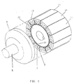
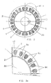
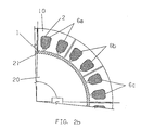
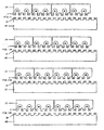
- Verfahren zum Betreiben einer untersynchronen Reluktanzstrommaschine, die mindestens einen Rotor (20) und mindestens einen Stator (10) mit einer aus mehreren Spulen (6a, 6b, 6c) gebildeten Wicklung (6) umfaßt, wobei:wobei das Verfahren gekennzeichnet ist durch den Schritt des Verfolgens einer relativen Position des Rotors (20) bezüglich des Statorsektors (11) und sequentielles Bestromen der Spulen (6a, 6b, 6c) gemäß den folgenden Arbeitsphasen:der Rotor (20) aus ferromagnetischen Platten gebildet ist und mehrere Längsrotorzähne (21 A, 21 B, 21 E) aufweist, die über eine Rotorfläche dem Stator (10) zugewandt gleichmäßig verteilt sind, wobei die Rotorzähne (21A, 21B, 21E) zu dem Stator (10) vorstehen,der Stator (10) aus einer Reihe magnetisch ungekoppelter oder schwach gekoppelter Statorsektoren (11) besteht, die Seite an Seite angeordnet sind und aus ferromagnetischen Platten bestehen, wobei jeder Statorsektor (11) mit mehreren Längsstatorzähnen (1A, 1E, 1I) versehen ist, die über eine Statorfläche dem Rotor (20) zugewandt gleichmäßig verteilt sind, wobei die Statorzähne (1A, 1E, 1I) zu den Rotorzähnen (21A, 21B, 21E) vorstehen,wobei jeder Statorsektor (11) mit e iner Spule der mehreren Spulen (6a, 6b, 6c) versehen ist, wobei die Spule so angeordnet ist, daß sie ferromagnetisches Material des jeweiligen Statorsektors (11) umgibt, damit ein Magnetfeld erzeugt wird, wenn die Spule über eine Stromquelle bestromt wird, unddie Gesamtzahl der Statorzähne (1A, 1E, 1I) von der Anzahl der Rotorzähne (21A, 21B, 21E) verschieden ist;a) Identifizierung eines Bereichs hoher Permeabilität zwischen einem Statorzahn (1A) eines ersten Statorsektors (11) und einem ersten Rotorzahn (21A), welcher Bereich hoher Permeabilität existiert wenn der Statorzahn (1A) mit dem Rotorzahn (21A) ausgerichtet ist,
Bestromen einer ersten Spule (6a) des ersten Statorsektors (11) gemeinsam mit einer zweiten Spule (6b) eines zweiten Statorsektors (11), welcher zweiter Statorsektor (11) sich in der der Bewegungsrichtung des Rotors (20) entgegengesetzten Richtung neben dem ersten Statorsektor (11) befindet, wobei der bestromende Zustand der ersten und zweiten Spule (6a, 6b) eine Verschiebung des Rotors (20) bezüglich des Stators (10) verursacht;b) Identifizierung eines Bereichs hoher Permeabilität zwischen einem Statorzahn (1E) eines zweiten Statorsektors (11) und einem zweiten Rotorzahn (21E), welcher Bereich hoher Permeabilität existiert wenn der Statorzahn (1E) mit dem Rotorzahn (21E) ausgerichtet ist,
Abschalten der ersten Spule (6a),
weiteres Bestromen der zweiten Spule (6b),
Bestromen einer dritten Spule (6c) eines dritten Statorsektors (11), welcher dritte Statorsektor (11) sich in der der Bewegungsrichtung des Rotors (20) entgegengesetzten Richtung neben dem zweiten Statorsektor (11) befindet, wobei der bestromte Zustand der zweiten und dritten Spule (6b, 6c) eine weitere Verschiebung des Rotors (20) bezüglich des Stators (10) verursacht; undc) selektives Bestromen und Abschalten von Spulen (6a, 6b, 6c) eines beliebigen Statorsektors (11) gemäß Arbeitsphase b), damit Spulen (6a, 6b, 6c) von zwei benachbarten Statorsektoren (11) immer bestromt sind und eine Sequenz von Bewegungen des Rotors (20) bezüglich des Stators (10) erzeugt wird. - Untersynchrone Reluktanzstrommaschine, die mindestens einen Rotor (20) und mindestens einen Stator (10) mit einer aus mehreren Spulen (6a, 6b, 6c) gebildeten Wicklung (6) umfaßt, wobei:dadurch gekennzeichnet, daß sie eine Überwachungseinrichtung (4) umfaßt, die eine relative Position des Rotors (20) bezüglich des Statorsektors (11) verfolgt und die Spulen (6a, 6b, 6c) gemäß den folgenden Arbeitsphasen sequentiell bestromt:der Rotor (20) aus ferromagnetischen Platten gebildet ist und mehrere Längsrotorzähne (21A, 21B, 21E) aufweist, die über eine Rotorfläche dem Stator (10) zugewandt gleichmäßig verteilt sind, wobei die Rotorzähne (21A, 21B, 21E) zu dem Stator (10) vorstehen,der Stator (10) aus einer Reihe magnetisch ungekoppelter oder schwach gekoppelter Statorsektoren (11) besteht, die Seite an Seite angeordnet sind und aus ferromagnetischen Platten bestehen, wobei jeder Statorsektor (11) mit mehreren Längsstatorzähnen (1A, 1E, 1I) versehen ist, die über eine Statorfläche dem Rotor (20) zugewandt gleichmäßig verteilt sind, wobei die Statorzähne (1A, 1E, 1I) zu den Rotorzähnen (21A, 21B, 21E) vorstehen,wobei jeder S tatorsektor (11) m it e iner S pule d er m ehreren S pulen (6a, 6 b, 6 c) versehen ist, wobei die Spule so angeordnet ist, daß sie ferromagnetisches Material des jeweiligen Statorsektors (11) umgibt, damit ein Magnetfeld erzeugt wird, wenn die Spule über eine Stromquelle bestromt wird, unddie Gesamtzahl der Statorzähne (1A, 1E, 1I) von der Anzahl der Rotorzähne (21A, 21B, 21E) verschieden ist;a) Identifizierung eines Bereichs hoher Permeabilität zwischen einem Statorzahn (1A) eines ersten Statorsektors (11) und einem ersten Rotorzahn (21A), welcher Bereich hoher Permeabilität existiert wenn der Statorzahn (1A) mit dem Rotorzahn (21A) ausgerichtet ist,
Bestromen einer ersten Spule (6a) des ersten Statorsektors (11) gemeinsam mit einer zweiten Spule (6b) eines zweiten Statorsektors (11), welcher zweiter Statorsektor (11) sich in der der Bewegungsrichtung des Rotors (20) entgegengesetzten Richtung neben dem ersten Statorsektor (11) befindet, wobei der bestromende Zustand der ersten und zweiten Spule (6a, 6b) eine Verschiebung des Rotors (20) bezüglich des Stators (10) verursacht;b) Identifizierung eines Bereichs hoher Permeabilität zwischen einem Statorzahn (1E) eines zweiten Statorsektors (11) und einem zweiten Rotorzahn (21E), welcher Bereich hoher Permeabilität existiert wenn der Statorzahn (1E) mit dem Rotorzahn (21E) ausgerichtet ist,
Abschalten der ersten Spule (6a),
weiteres Bestromen der zweiten Spule (6b),
Bestromen einer dritten Spule (6c) eines dritten Statorsektors (11), welcher dritte Statorsektor (11) sich in der der Bewegungsrichtung des Rotors (20) entgegengesetzten Richtung neben dem zweiten Statorsektor (11) befindet, wobei der bestromte Zustand der zweiten und dritten Spule (6b, 6c) eine weitere Verschiebung des Rotors (20) bezüglich des Stators (10) verursacht; undc) selektives Bestromen und Abschalten von Spulen (6a, 6b, 6c) eines beliebigen Statorsektors (11) gemäß Arbeitsphase b), damit Spulen (6a, 6b, 6c) von zwei benachbarten Statorsektoren (11) immer bestromt sind und eine Sequenz von Bewegungen des Rotors (20) bezüglich des Stators (10) erzeugt wird. - Maschine nach Anspruch 2, dadurch gekennzeichnet, daß jede Spule (6a, 6b, 6c) in mindestens zwei Nuten (2) des jeweiligen Sektors (11) des Stators (10) angeordnet ist.
- Maschine nach Anspruch 2, dadurch gekennzeichnet, daß die Überwachungseinrichtung (4) ein Detektor vom Hall-Typ ist.
- Maschine nach Anspruch 2, dadurch gekennzeichnet, daß die Überwachungseinrichtung (4) ein Codierer oder ein Drehmelder ist.
- Maschine nach Anspruch 2, dadurch gekennzeichnet, daß sie ein untersynchroner Reluktanzdrehmotor ist.
- Maschine nach Anspruch 2, dadurch gekennzeichnet, daß sie ein untersynchroner Reluktanzlinearmotor ist.
- Maschine nach Anspruch 2, dadurch gekennzeichnet, daß sie ein untersynchroner Reluktanzscheibenmotor ist.
Applications Claiming Priority (5)
| Application Number | Priority Date | Filing Date | Title |
|---|---|---|---|
| BR9804426 | 1998-10-16 | ||
| BR9804426-5A BR9804426A (pt) | 1998-10-16 | 1998-10-16 | Máquina elétrica de relutância subsìncrona. |
| JP2000008195A JP2001204162A (ja) | 1998-10-16 | 2000-01-17 | 次同期リラクタンス電気機械 |
| CA002297337A CA2297337C (en) | 1998-10-16 | 2000-01-27 | Subsynchronous reluctance electrical machine |
| CN00100707A CN1307394A (zh) | 1998-10-16 | 2000-02-01 | 次同步磁阻电机 |
Publications (3)
| Publication Number | Publication Date |
|---|---|
| EP0994555A2 EP0994555A2 (de) | 2000-04-19 |
| EP0994555A3 EP0994555A3 (de) | 2001-05-16 |
| EP0994555B1 true EP0994555B1 (de) | 2004-05-26 |
Family
ID=27425285
Family Applications (1)
| Application Number | Title | Priority Date | Filing Date |
|---|---|---|---|
| EP99119802A Expired - Lifetime EP0994555B1 (de) | 1998-10-16 | 1999-10-06 | Untersynchrone elektrische Reluktanzmaschine |
Country Status (11)
| Country | Link |
|---|---|
| US (1) | US6239530B1 (de) |
| EP (1) | EP0994555B1 (de) |
| JP (2) | JP2000152579A (de) |
| KR (1) | KR100633706B1 (de) |
| CN (1) | CN1307394A (de) |
| AT (1) | ATE268068T1 (de) |
| BR (1) | BR9804426A (de) |
| CA (1) | CA2297337C (de) |
| DE (1) | DE69917557T2 (de) |
| ES (1) | ES2222648T3 (de) |
| PT (1) | PT994555E (de) |
Families Citing this family (26)
| Publication number | Priority date | Publication date | Assignee | Title |
|---|---|---|---|---|
| FR2806951B1 (fr) * | 2000-03-31 | 2002-06-14 | Aro | Dispositif de motorisation electrique pour pince d'outillage |
| US6648252B2 (en) * | 2000-10-04 | 2003-11-18 | Emerson Electric Co. | Switched reluctance machine and food waste disposer employing switched reluctance machine |
| US6481652B2 (en) | 2000-11-28 | 2002-11-19 | Emerson Electric Co. | Food waste disposer having variable speed motor and methods of operating same |
| US6854673B2 (en) * | 2000-11-28 | 2005-02-15 | Emerson Electric Co. | Food waste disposer having a variable speed motor |
| US7012350B2 (en) * | 2001-01-04 | 2006-03-14 | Emerson Electric Co. | Segmented stator switched reluctance machine |
| US6584813B2 (en) | 2001-03-26 | 2003-07-01 | Emerson Electric Co. | Washing machine including a segmented stator switched reluctance motor |
| US20020093269A1 (en) * | 2001-01-16 | 2002-07-18 | Harter Bernard G. | Slot area undercut for segmented stators |
| US6744166B2 (en) * | 2001-01-04 | 2004-06-01 | Emerson Electric Co. | End cap assembly for a switched reluctance electric machine |
| US6700284B2 (en) * | 2001-03-26 | 2004-03-02 | Emerson Electric Co. | Fan assembly including a segmented stator switched reluctance fan motor |
| US6897591B2 (en) * | 2001-03-26 | 2005-05-24 | Emerson Electric Co. | Sensorless switched reluctance electric machine with segmented stator |
| GB0209794D0 (en) * | 2002-04-30 | 2002-06-05 | Univ Newcastle | Switched reluctance electrical machine |
| DE102006005046A1 (de) * | 2006-02-03 | 2007-08-09 | Siemens Ag | Elektrische Maschine mit ungleichmäßigen Polzähnen |
| EP2171827A1 (de) * | 2007-07-27 | 2010-04-07 | The Texas A&M University System | Motoren-generatoren mit kurzem flussweg |
| CN101465588B (zh) * | 2007-12-21 | 2015-05-13 | 张玉宝 | 一种磁阻电动机及提高电动机有效功率的方法 |
| US7851966B2 (en) * | 2008-01-10 | 2010-12-14 | Rippel Wally E | Stator for electric machine with improved efficiency and thermal performance |
| JP4747184B2 (ja) * | 2008-04-14 | 2011-08-17 | 本田技研工業株式会社 | 電動機 |
| JP4505524B2 (ja) * | 2008-07-22 | 2010-07-21 | 本田技研工業株式会社 | 動力装置 |
| CN102160267B (zh) * | 2008-08-29 | 2013-08-21 | 莫戈公司 | 永磁型步进电动机 |
| CN102239626B (zh) * | 2009-09-08 | 2015-01-28 | 莫戈公司 | 带有小步幅间隔的步进马达 |
| FR2961970B1 (fr) * | 2010-06-25 | 2017-03-10 | Valeo Systemes De Controle Moteur | Moteur electrique a courant alternatif d'un dispositif electrique combine d'alimentation et de charge |
| DE102012103677A1 (de) * | 2012-04-26 | 2013-10-31 | Feaam Gmbh | Elektrische Maschine |
| RU2543522C2 (ru) * | 2013-07-23 | 2015-03-10 | Общество с ограниченной ответственностью "Механотроника" | Мехатронное устройство |
| US11255612B2 (en) | 2014-07-25 | 2022-02-22 | Enure, Inc. | Wound strip machine |
| DE112015003443T5 (de) | 2014-07-25 | 2017-04-06 | Prippell Technologies, Llc | Fluidgekühlte gewundene Streifenstruktur |
| US10756583B2 (en) | 2014-07-25 | 2020-08-25 | Enure, Inc. | Wound strip machine |
| DE102017105977A1 (de) * | 2017-03-21 | 2018-09-27 | Schaeffler Technologies AG & Co. KG | Dynamoelektrische Maschine mit reduzierten Rastmomenten |
Family Cites Families (14)
| Publication number | Priority date | Publication date | Assignee | Title |
|---|---|---|---|---|
| US4315171A (en) * | 1977-05-23 | 1982-02-09 | Ernest Schaeffer | Step motors |
| US4198582A (en) * | 1977-06-24 | 1980-04-15 | Exxon Research & Engineering Co. | High performance stepper motor |
| US4475051A (en) * | 1982-08-27 | 1984-10-02 | International Business Machines Corporation | Low inertia high torque variable reluctance motor |
| FR2573586B1 (fr) * | 1984-11-19 | 1988-08-05 | Jarret Tech Electr | Perfectionnements aux moteurs a reluctance variable |
| US5173651A (en) * | 1985-06-28 | 1992-12-22 | Kollmorgen Technologies Corporation | Electrical drive systems |
| US4713570A (en) * | 1986-06-04 | 1987-12-15 | Pacific Scientific Co. | Magnetically enhanced variable reluctance motor systems |
| US4733117A (en) * | 1987-04-27 | 1988-03-22 | The Superior Electric Company | Reluctance synchro/resolver |
| US4990809A (en) * | 1987-04-27 | 1991-02-05 | The Superior Electric Company | Variable reluctance motor |
| US4995159A (en) * | 1988-08-15 | 1991-02-26 | Pacific Scientific Company | Method of making an electronically commutated reluctance motor |
| JP2599061B2 (ja) * | 1991-12-13 | 1997-04-09 | オリエンタルモーター株式会社 | ステッピングモータ |
| IT1262572B (it) * | 1993-11-03 | 1996-07-04 | Alessandro Dreoni | Motore elettrico lineare o rotativo sincrono a riluttanza variabile con sviluppo volumetrico della forza |
| US6025668A (en) * | 1995-12-08 | 2000-02-15 | Dana Corporation | Variable reluctance motor having bifurcated stator poles |
| DE19743380C1 (de) * | 1997-09-30 | 1999-03-25 | Emf 97 Gmbh | Reluktanzmotor |
| US6051898A (en) * | 1998-01-02 | 2000-04-18 | Japan Servo Co., Ltd. | Stepping motor having external rotor and electromagnetic-combined-permanent-magnet stator |
-
1998
- 1998-10-16 BR BR9804426-5A patent/BR9804426A/pt not_active Application Discontinuation
-
1999
- 1999-09-29 US US09/408,298 patent/US6239530B1/en not_active Expired - Lifetime
- 1999-10-06 ES ES99119802T patent/ES2222648T3/es not_active Expired - Lifetime
- 1999-10-06 AT AT99119802T patent/ATE268068T1/de not_active IP Right Cessation
- 1999-10-06 PT PT99119802T patent/PT994555E/pt unknown
- 1999-10-06 EP EP99119802A patent/EP0994555B1/de not_active Expired - Lifetime
- 1999-10-06 DE DE69917557T patent/DE69917557T2/de not_active Expired - Lifetime
- 1999-10-12 KR KR1019990044156A patent/KR100633706B1/ko not_active IP Right Cessation
- 1999-10-18 JP JP11295559A patent/JP2000152579A/ja active Pending
-
2000
- 2000-01-17 JP JP2000008195A patent/JP2001204162A/ja active Pending
- 2000-01-27 CA CA002297337A patent/CA2297337C/en not_active Expired - Fee Related
- 2000-02-01 CN CN00100707A patent/CN1307394A/zh active Pending
Also Published As
| Publication number | Publication date |
|---|---|
| PT994555E (pt) | 2004-10-29 |
| CN1307394A (zh) | 2001-08-08 |
| ES2222648T3 (es) | 2005-02-01 |
| ATE268068T1 (de) | 2004-06-15 |
| JP2001204162A (ja) | 2001-07-27 |
| EP0994555A2 (de) | 2000-04-19 |
| US6239530B1 (en) | 2001-05-29 |
| CA2297337A1 (en) | 2001-07-27 |
| JP2000152579A (ja) | 2000-05-30 |
| DE69917557D1 (de) | 2004-07-01 |
| BR9804426A (pt) | 2000-05-16 |
| KR20000029016A (ko) | 2000-05-25 |
| CA2297337C (en) | 2008-04-08 |
| KR100633706B1 (ko) | 2006-10-13 |
| DE69917557T2 (de) | 2005-07-14 |
| EP0994555A3 (de) | 2001-05-16 |
Similar Documents
| Publication | Publication Date | Title |
|---|---|---|
| EP0994555B1 (de) | Untersynchrone elektrische Reluktanzmaschine | |
| JP5318758B2 (ja) | リングコイルモータ | |
| US4719378A (en) | Brushless motor having permanent magnet rotor and salient pole stator | |
| US4197488A (en) | Electrical machine | |
| US4990809A (en) | Variable reluctance motor | |
| US4995159A (en) | Method of making an electronically commutated reluctance motor | |
| EP0559818B1 (de) | Kommutierter mehrphasenreluktanzmotor | |
| US4237396A (en) | Electromagnetic machines with permanent magnet excitation | |
| US6683397B2 (en) | Electric machine having at least one magnetic field detector | |
| KR101228013B1 (ko) | 비대칭 극을 갖는 직류 모터 | |
| JP3693100B2 (ja) | 多相トラバース磁束機械 | |
| JPS6341307B2 (de) | ||
| US4823039A (en) | Electrical machines | |
| EP0465462A4 (en) | Electronically commutated reluctance motor | |
| US4978878A (en) | Electric multipolar machine | |
| US20130057105A1 (en) | Permanent magnet motors and methods of assembling the same | |
| EP0848482A2 (de) | Bürstenloser Gleichstrommotor | |
| US6975057B2 (en) | Rotary electric machine having a stator made up of sectors assembled together | |
| US8373328B2 (en) | Pulsed multi-rotor constant air gap switched reluctance motor | |
| KR100337665B1 (ko) | 영구자석전동기 | |
| EP0735652A1 (de) | Geschaltete Reluktanzmaschine | |
| WO2022020226A1 (en) | Variable reluctance step motor having enhanced holding torque | |
| US5438227A (en) | Linear pulse motor | |
| JP4248778B2 (ja) | 永久磁石形電動機の回転子 | |
| US4608505A (en) | Commutatorless d.c. electric motor |
Legal Events
| Date | Code | Title | Description |
|---|---|---|---|
| PUAI | Public reference made under article 153(3) epc to a published international application that has entered the european phase |
Free format text: ORIGINAL CODE: 0009012 |
|
| AK | Designated contracting states |
Kind code of ref document: A2 Designated state(s): AT BE CH CY DE DK ES FI FR GB GR IE IT LI LU MC NL PT SE |
|
| AX | Request for extension of the european patent |
Free format text: AL;LT;LV;MK;RO;SI |
|
| PUAL | Search report despatched |
Free format text: ORIGINAL CODE: 0009013 |
|
| AK | Designated contracting states |
Kind code of ref document: A3 Designated state(s): AT BE CH CY DE DK ES FI FR GB GR IE IT LI LU MC NL PT SE |
|
| AX | Request for extension of the european patent |
Free format text: AL;LT;LV;MK;RO;SI |
|
| 17P | Request for examination filed |
Effective date: 20010920 |
|
| 17Q | First examination report despatched |
Effective date: 20011109 |
|
| AKX | Designation fees paid |
Free format text: AT BE CH CY DE DK ES FI FR GB GR IE IT LI LU MC NL PT SE |
|
| GRAH | Despatch of communication of intention to grant a patent |
Free format text: ORIGINAL CODE: EPIDOS IGRA |
|
| RAP1 | Party data changed (applicant data changed or rights of an application transferred) |
Owner name: INVENTIO AG |
|
| GRAS | Grant fee paid |
Free format text: ORIGINAL CODE: EPIDOSNIGR3 |
|
| GRAA | (expected) grant |
Free format text: ORIGINAL CODE: 0009210 |
|
| AK | Designated contracting states |
Kind code of ref document: B1 Designated state(s): AT BE CH CY DE DK ES FI FR GB GR IE IT LI LU MC NL PT SE |
|
| PG25 | Lapsed in a contracting state [announced via postgrant information from national office to epo] |
Ref country code: CY Free format text: LAPSE BECAUSE OF FAILURE TO SUBMIT A TRANSLATION OF THE DESCRIPTION OR TO PAY THE FEE WITHIN THE PRESCRIBED TIME-LIMIT Effective date: 20040526 |
|
| REG | Reference to a national code |
Ref country code: GB Ref legal event code: FG4D |
|
| REG | Reference to a national code |
Ref country code: CH Ref legal event code: EP |
|
| REG | Reference to a national code |
Ref country code: IE Ref legal event code: FG4D |
|
| REF | Corresponds to: |
Ref document number: 69917557 Country of ref document: DE Date of ref document: 20040701 Kind code of ref document: P |
|
| PG25 | Lapsed in a contracting state [announced via postgrant information from national office to epo] |
Ref country code: GR Free format text: LAPSE BECAUSE OF FAILURE TO SUBMIT A TRANSLATION OF THE DESCRIPTION OR TO PAY THE FEE WITHIN THE PRESCRIBED TIME-LIMIT Effective date: 20040826 Ref country code: DK Free format text: LAPSE BECAUSE OF FAILURE TO SUBMIT A TRANSLATION OF THE DESCRIPTION OR TO PAY THE FEE WITHIN THE PRESCRIBED TIME-LIMIT Effective date: 20040826 |
|
| REG | Reference to a national code |
Ref country code: SE Ref legal event code: TRGR |
|
| PG25 | Lapsed in a contracting state [announced via postgrant information from national office to epo] |
Ref country code: LU Free format text: LAPSE BECAUSE OF NON-PAYMENT OF DUE FEES Effective date: 20041006 Ref country code: IE Free format text: LAPSE BECAUSE OF NON-PAYMENT OF DUE FEES Effective date: 20041006 |
|
| REG | Reference to a national code |
Ref country code: PT Ref legal event code: SC4A Free format text: AVAILABILITY OF NATIONAL TRANSLATION Effective date: 20040820 |
|
| PG25 | Lapsed in a contracting state [announced via postgrant information from national office to epo] |
Ref country code: MC Free format text: LAPSE BECAUSE OF NON-PAYMENT OF DUE FEES Effective date: 20041031 |
|
| ET | Fr: translation filed | ||
| REG | Reference to a national code |
Ref country code: ES Ref legal event code: FG2A Ref document number: 2222648 Country of ref document: ES Kind code of ref document: T3 |
|
| PLBE | No opposition filed within time limit |
Free format text: ORIGINAL CODE: 0009261 |
|
| STAA | Information on the status of an ep patent application or granted ep patent |
Free format text: STATUS: NO OPPOSITION FILED WITHIN TIME LIMIT |
|
| 26N | No opposition filed |
Effective date: 20050301 |
|
| REG | Reference to a national code |
Ref country code: IE Ref legal event code: MM4A |
|
| PGFP | Annual fee paid to national office [announced via postgrant information from national office to epo] |
Ref country code: NL Payment date: 20071016 Year of fee payment: 9 Ref country code: ES Payment date: 20071030 Year of fee payment: 9 |
|
| PGFP | Annual fee paid to national office [announced via postgrant information from national office to epo] |
Ref country code: AT Payment date: 20071015 Year of fee payment: 9 Ref country code: FI Payment date: 20071015 Year of fee payment: 9 Ref country code: IT Payment date: 20071024 Year of fee payment: 9 |
|
| PGFP | Annual fee paid to national office [announced via postgrant information from national office to epo] |
Ref country code: BE Payment date: 20071123 Year of fee payment: 9 Ref country code: SE Payment date: 20071012 Year of fee payment: 9 |
|
| PGFP | Annual fee paid to national office [announced via postgrant information from national office to epo] |
Ref country code: GB Payment date: 20071023 Year of fee payment: 9 Ref country code: CH Payment date: 20080117 Year of fee payment: 9 |
|
| REG | Reference to a national code |
Ref country code: PT Ref legal event code: MM4A Free format text: LAPSE DUE TO NON-PAYMENT OF FEES Effective date: 20090406 |
|
| BERE | Be: lapsed |
Owner name: *INVENTIO A.G. Effective date: 20081031 |
|
| REG | Reference to a national code |
Ref country code: CH Ref legal event code: PL |
|
| EUG | Se: european patent has lapsed | ||
| GBPC | Gb: european patent ceased through non-payment of renewal fee |
Effective date: 20081006 |
|
| NLV4 | Nl: lapsed or anulled due to non-payment of the annual fee |
Effective date: 20090501 |
|
| PG25 | Lapsed in a contracting state [announced via postgrant information from national office to epo] |
Ref country code: NL Free format text: LAPSE BECAUSE OF NON-PAYMENT OF DUE FEES Effective date: 20090501 Ref country code: FI Free format text: LAPSE BECAUSE OF NON-PAYMENT OF DUE FEES Effective date: 20081006 |
|
| PG25 | Lapsed in a contracting state [announced via postgrant information from national office to epo] |
Ref country code: PT Free format text: LAPSE BECAUSE OF NON-PAYMENT OF DUE FEES Effective date: 20090406 Ref country code: IT Free format text: LAPSE BECAUSE OF NON-PAYMENT OF DUE FEES Effective date: 20081006 Ref country code: AT Free format text: LAPSE BECAUSE OF NON-PAYMENT OF DUE FEES Effective date: 20081006 |
|
| PG25 | Lapsed in a contracting state [announced via postgrant information from national office to epo] |
Ref country code: BE Free format text: LAPSE BECAUSE OF NON-PAYMENT OF DUE FEES Effective date: 20081031 |
|
| PG25 | Lapsed in a contracting state [announced via postgrant information from national office to epo] |
Ref country code: LI Free format text: LAPSE BECAUSE OF NON-PAYMENT OF DUE FEES Effective date: 20081031 Ref country code: CH Free format text: LAPSE BECAUSE OF NON-PAYMENT OF DUE FEES Effective date: 20081031 |
|
| PG25 | Lapsed in a contracting state [announced via postgrant information from national office to epo] |
Ref country code: GB Free format text: LAPSE BECAUSE OF NON-PAYMENT OF DUE FEES Effective date: 20081006 |
|
| PGFP | Annual fee paid to national office [announced via postgrant information from national office to epo] |
Ref country code: PT Payment date: 20070924 Year of fee payment: 9 |
|
| REG | Reference to a national code |
Ref country code: ES Ref legal event code: FD2A Effective date: 20081007 |
|
| PG25 | Lapsed in a contracting state [announced via postgrant information from national office to epo] |
Ref country code: ES Free format text: LAPSE BECAUSE OF NON-PAYMENT OF DUE FEES Effective date: 20081007 |
|
| PG25 | Lapsed in a contracting state [announced via postgrant information from national office to epo] |
Ref country code: SE Free format text: LAPSE BECAUSE OF NON-PAYMENT OF DUE FEES Effective date: 20081007 |
|
| PGFP | Annual fee paid to national office [announced via postgrant information from national office to epo] |
Ref country code: DE Payment date: 20101022 Year of fee payment: 12 |
|
| PGFP | Annual fee paid to national office [announced via postgrant information from national office to epo] |
Ref country code: FR Payment date: 20111103 Year of fee payment: 13 |
|
| REG | Reference to a national code |
Ref country code: FR Ref legal event code: ST Effective date: 20130628 |
|
| PG25 | Lapsed in a contracting state [announced via postgrant information from national office to epo] |
Ref country code: DE Free format text: LAPSE BECAUSE OF NON-PAYMENT OF DUE FEES Effective date: 20130501 |
|
| REG | Reference to a national code |
Ref country code: DE Ref legal event code: R119 Ref document number: 69917557 Country of ref document: DE Effective date: 20130501 |
|
| PG25 | Lapsed in a contracting state [announced via postgrant information from national office to epo] |
Ref country code: FR Free format text: LAPSE BECAUSE OF NON-PAYMENT OF DUE FEES Effective date: 20121031 |