EP0994498B1 - Interrupteur avec support isolant - Google Patents
Interrupteur avec support isolant Download PDFInfo
- Publication number
- EP0994498B1 EP0994498B1 EP99112920A EP99112920A EP0994498B1 EP 0994498 B1 EP0994498 B1 EP 0994498B1 EP 99112920 A EP99112920 A EP 99112920A EP 99112920 A EP99112920 A EP 99112920A EP 0994498 B1 EP0994498 B1 EP 0994498B1
- Authority
- EP
- European Patent Office
- Prior art keywords
- switch
- temperature
- contact
- electrode
- external terminal
- Prior art date
- Legal status (The legal status is an assumption and is not a legal conclusion. Google has not performed a legal analysis and makes no representation as to the accuracy of the status listed.)
- Expired - Lifetime
Links
Images


Classifications
-
- H—ELECTRICITY
- H01—ELECTRIC ELEMENTS
- H01H—ELECTRIC SWITCHES; RELAYS; SELECTORS; EMERGENCY PROTECTIVE DEVICES
- H01H37/00—Thermally-actuated switches
- H01H37/02—Details
- H01H37/32—Thermally-sensitive members
- H01H37/52—Thermally-sensitive members actuated due to deflection of bimetallic element
- H01H37/54—Thermally-sensitive members actuated due to deflection of bimetallic element wherein the bimetallic element is inherently snap acting
- H01H37/5418—Thermally-sensitive members actuated due to deflection of bimetallic element wherein the bimetallic element is inherently snap acting using cantilevered bimetallic snap elements
-
- H—ELECTRICITY
- H01—ELECTRIC ELEMENTS
- H01H—ELECTRIC SWITCHES; RELAYS; SELECTORS; EMERGENCY PROTECTIVE DEVICES
- H01H1/00—Contacts
- H01H1/50—Means for increasing contact pressure, preventing vibration of contacts, holding contacts together after engagement, or biasing contacts to the open position
- H01H1/504—Means for increasing contact pressure, preventing vibration of contacts, holding contacts together after engagement, or biasing contacts to the open position by thermal means
-
- H—ELECTRICITY
- H01—ELECTRIC ELEMENTS
- H01H—ELECTRIC SWITCHES; RELAYS; SELECTORS; EMERGENCY PROTECTIVE DEVICES
- H01H37/00—Thermally-actuated switches
- H01H37/02—Details
- H01H37/32—Thermally-sensitive members
- H01H37/52—Thermally-sensitive members actuated due to deflection of bimetallic element
- H01H37/54—Thermally-sensitive members actuated due to deflection of bimetallic element wherein the bimetallic element is inherently snap acting
- H01H2037/5445—Thermally-sensitive members actuated due to deflection of bimetallic element wherein the bimetallic element is inherently snap acting with measures for avoiding slow break of contacts during the creep phase of the snap bimetal
-
- H—ELECTRICITY
- H01—ELECTRIC ELEMENTS
- H01H—ELECTRIC SWITCHES; RELAYS; SELECTORS; EMERGENCY PROTECTIVE DEVICES
- H01H37/00—Thermally-actuated switches
- H01H37/02—Details
- H01H37/32—Thermally-sensitive members
- H01H37/52—Thermally-sensitive members actuated due to deflection of bimetallic element
- H01H37/54—Thermally-sensitive members actuated due to deflection of bimetallic element wherein the bimetallic element is inherently snap acting
- H01H2037/5463—Thermally-sensitive members actuated due to deflection of bimetallic element wherein the bimetallic element is inherently snap acting the bimetallic snap element forming part of switched circuit
-
- H—ELECTRICITY
- H01—ELECTRIC ELEMENTS
- H01H—ELECTRIC SWITCHES; RELAYS; SELECTORS; EMERGENCY PROTECTIVE DEVICES
- H01H37/00—Thermally-actuated switches
- H01H37/02—Details
- H01H37/32—Thermally-sensitive members
- H01H37/52—Thermally-sensitive members actuated due to deflection of bimetallic element
- H01H37/54—Thermally-sensitive members actuated due to deflection of bimetallic element wherein the bimetallic element is inherently snap acting
- H01H37/5427—Thermally-sensitive members actuated due to deflection of bimetallic element wherein the bimetallic element is inherently snap acting encapsulated in sealed miniaturised housing
-
- H—ELECTRICITY
- H01—ELECTRIC ELEMENTS
- H01H—ELECTRIC SWITCHES; RELAYS; SELECTORS; EMERGENCY PROTECTIVE DEVICES
- H01H71/00—Details of the protective switches or relays covered by groups H01H73/00 - H01H83/00
- H01H71/10—Operating or release mechanisms
- H01H71/12—Automatic release mechanisms with or without manual release
- H01H71/14—Electrothermal mechanisms
- H01H71/16—Electrothermal mechanisms with bimetal element
Definitions
- the present invention relates to a switch with a Isolierstoffong, on which a first and a second external connection are arranged, as well as a temperature-dependent Rear derailleur that depending on its temperature between an electrically conductive the first and the second external connection Connection for one to be passed through the switch produces electrical current, and a switching device that its Geometric shape depending on the temperature between a closing and changed an open position and in its closed position leads the current, and includes an actuator that with the Switching element is electrically and mechanically connected in series.
- Such a switch is known from US 4,636,766.
- the known switch comprises a U-shaped bimetal element as a switching element with two legs of different lengths. On a movable contact part is attached to the long leg, that interacts with a switch-proof counter contact that again with one of the two external connections in electrical conductive connection.
- the shorter leg of the U-shaped bimetal element is on the free end of an actuator designed as a lever arm attached that with its other end firmly to the housing is connected as well as with the other of the two external connections is in an electrically conductive connection.
- the actuator is another bimetallic element that is so on the U-shaped bimetallic element is agreed that the two bimetallic elements deform in opposite directions with temperature changes and thus the contact pressure between the movable contact part and receive the mating contact fixed to the housing.
- This switch is intended as a breaker for high currents, which leads to a strong warming of the bimetallic elements lead, which ultimately the movable contact part is lifted off the fixed counter contact. Influences of Ambient temperature are the opposite Deformation of the bimetallic elements is compensated.
- the two bimetal elements are very different geometrically are designed, they also have different long-term stabilities on, so that from time to time a readjustment would be required. However, this is not in use more possible, so that overall long-term stability and thus the functional reliability leaves something to be desired.
- Another disadvantage of this construction is that large height due to the U-shaped bimetal element.
- this switch has the disadvantage that it closes again automatically after cooling, i.e. none Has self-holding function, the reclosing and thus Switch on the electrical protected by the switch Device prevented.
- Switches with self-holding function are generally known at They are switched in parallel to the temperature-dependent switching mechanism Self-holding resistor connected between the two external connections.
- the switch When the switch is closed, the Self-holding resistor electrically short-circuited by the switch mechanism, so that it is de-energized.
- the rear derailleur opens the rear derailleur, a residual current flows through the self-holding resistor depending on the applied voltage as well its resistance value heats up so far that it is temperature-dependent Switch mechanism at a temperature above the response temperature stops so that it stays open.
- Another current-dependent known from EP 0 103 792 B1 Switch has a bimetal spring tongue as a switching element on, which is attached to the one external connection and to her free end carries a movable contact part that with a Counter-contact cooperates, which at the free end of an elongated Spring element is arranged, the other end on the other external connector is attached so that the current through the Series connection from spring element and bimetal spring tongue flows.
- the elastic mounting of the counter contact ensures a low mechanical stress on the bimetal spring tongue because of the Mating contact yields to a limited extent when the bimetal spring tongue changed their geometric shape due to a change in temperature. This causes irreversible deformation of the bimetallic spring tongue avoided, leading to a shift in the switching temperature could lead.
- a disadvantage of this switch is that the bimetal spring tongue like all bimetal elements in the transition from In the open position, a so-called creep phase passes through, in the course of a temperature increase or lowers the bimetallic element creepingly deformed without however from its e.g. convex low temperature position already to snap into its concave high temperature position.
- This Creeping phase occurs every time the temperature changes of the bimetal element either from above or from below Jump temperature approaches and leads to noticeable changes in conformation. Particularly as a result of aging or long-term use can the creep behavior of a bimetal element furthermore also change.
- sneaking can cause that the pressure of the contact against the counter contact decreases, which creates undefined switching states.
- the closing movement can make contact during the creeping phase gradually approach the counter contact, thereby increasing the risk of a Arc can be caused.
- the inventor of the present application has recognized that that it is possible when using a flat cover electrode is a flat self-holding resistance on the inside to be arranged without noticeably influencing the overall height. in the In contrast to a block-shaped PTC element, such a e.g. Sheet resistance namely such a small thickness, that this leads to a hardly noticeable increase in the thickness of the Cover electrode leads.
- the actuator is a Includes spring element, the actuating force largely independent of temperature is, and the actuator is a temperature-dependent Has actuating force that is greater than in its creeping phase the force of the spring element.
- the inventor of the present application has recognized that the e.g. known from DE 21 21 802 C mechanical and electrical parallel arrangement of temperature-neutral spring element and switching element in an electrical and mechanical series connection modified and used in the new switch can be a number of other advantages in the unite new switch.
- the temperature-neutral spring element exercises on the bimetal element no longer exert pressure that hinders its deformation, it rather resembles the deformation of the bimetal element in the creeping phase through its own deformation in such a way that movable Contact part and fixed counter contact with each other in such a way stay safely in the system for a low contact resistance is taken care of.
- the contact pressure remains below the Switching temperature largely independent of the temperature.
- the creeping phase of the bimetallic element is therefore no longer as suppressed in the prior art, but balanced so to speak, the bimetal element can namely in the Deform creep phase almost unhindered, making the changes the geometry is balanced by the spring element that the switch remains securely closed.
- the temperature-dependent actuating force of the bimetal element chosen so that they are larger in the creeping phase is the largely temperature-neutral actuating force of the Spring element, which is thus the "rigid" bimetal element only "leads".
- a big advantage of the new switch is its simple Construction, next to a housing-fixed counter contact is only a bimetal element is required, the spring element is temperature-neutral and therefore inexpensive. Overall, bimetal element and spring element to each other with respect to the actuating force be coordinated, but no longer additionally regarding their temperature behavior, because the rear derailleur straightens yourself, so to speak. This makes it a standard spring element possible for all temperature ranges, making an essential one Rationalization effect is achieved. Through this construction a low overall height can also be realized, whereby at different switching temperatures no new individual Adjustment is required, just the bimetal element must have the same spring properties but different switching temperatures be interpreted.
- Another advantage is that tolerances and fluctuations in the switching temperature by guiding through the temperature-neutral Spring element to be balanced.
- the second external connection is connected to a bottom electrode with which a Movable contact part cooperates that on the switching element is provided, and between the lid electrode and the bottom electrode a connecting element is arranged, the Self-holding resistor connects to the bottom electrode.
- the connecting element can either be installed as a separate part in the Switches are inserted, or beforehand on the cover electrode or the bottom electrode. complicated Solder connections or electrical wire connections are thus not required for contacting the self-holding resistor.
- a flat series resistor is arranged which electrically between the first outer terminal and the first end of the spring element is switched.
- an insulation layer is arranged on the at least one resistance track is arranged, one end with the first external connection and the other end with a contact surface is connected to a contact surface of the connecting element or in contact with the spring element.
- the connecting element is one the contact plate on the insulating material carrier, which is connected to the Contact surface is in contact, as well as facing the bottom electrode Has contact bracket, which between them one of the Clamp the upright tab on the base electrode.
- the spring element is on its first end is T-shaped, with this T-shaped End rests on the insulating material carrier and on this T-shaped end has a contact surface that is in contact with the contact surface of the series resistance is in the system.
- the spring element and the switching element are essentially flat, sheet-like parts that are extend to the same side in a V-shape away from their connection point.
- This measure has the advantage that compared to the generic switch, the overall height is significantly reduced, and also a slight longitudinal extension because of the "folded back" free end of the switching element reached becomes.
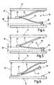
- Fig. 1 generally shows a new switch that is shown in schematic longitudinal section.
- the new switch 10 has a first external connection 11, the one piece with a flat or flat lid electrode 12 is connected. Furthermore, a second external connection 14 is provided, which is formed in one piece with a bottom electrode 15 is. The cover electrode 12 and the bottom electrode 15 are on an insulating substrate 16 held the lid electrode 12 and the bottom electrode 15 spaced parallel to each other holds.
- the insulating material carrier 16 is basically open on the side 1, an embodiment is shown in which the insulating material carrier 16 is a pot-shaped lower housing part 17 includes that around the bottom electrode 15 by injection molding or potting is designed such that the bottom electrode 15 is an integral part of the lower housing part 17.
- the Lower housing part 17 is closed by the cover electrode 12, that of a heat-welded one indicated at 18 Edge of the insulating substrate 16 is held captive.
- the switching mechanism 19 comprises a mechanical and electrical series connection from a spring element 21 and a switching element 22, which by a 23rd indicated connection are connected.
- the switching element 22 is a bimetal element in the present case.
- the spring element 21 has a largely temperature-independent Actuating force, what in the context of the present invention means that the positioning force or spring force of the spring element 21 in the range of the permissible operating temperature of the Switch 10 does not change noticeably.
- the positioning force of the bimetal element is strongly temperature dependent and also in the so-called creep phase is already so large that the spring element 21 do not hinder the deformation of the bimetallic element Pressure on that at constant temperature in this spring system thus can exert rigid bimetal element.
- the spring element 21 has its first, T-shaped end 25 In Fig. 1 top right in contact with the cover electrode 12 and leads with its second end 26 into the connection 23 to the Switching element 22.
- the switching element 22 carries at its free end 27 a movable contact part 28, which with a switch-fixed Counter-contact 29 cooperates, which on the bottom electrode 15 is trained.
- a second interior 34 is provided in the insulating material carrier 16, into which a connecting element 35 projects from above, that with a bent-up tab 36 of the bottom electrode 15 electrical system.
- the connecting element 35 also in contact with the self-holding resistor, as will now be explained with reference to FIG. 2.
- Fig. 2 it can first be seen that the lower housing part 17th a base set back towards its edge 18 37 has, on which the T-shaped second end 25 of the spring element 21 rests.
- This T-shaped second end 25 has an approach 38 on which a contact surface 39 for contacting the series resistance is provided.
- a contact plate is located on the base 37b 41 of the connecting element 35. Extend from the contact plate 41 down two contact brackets 42, 43, which between pinch the tab 36 of the bottom electrode 15. The Contact plate 41 comes into contact with the self-holding resistor, as it is now based on the bottom view of the lid electrode 12 is explained in Fig. 3a.
- the cover electrode 12 is initially large-area with an insulation layer 45 provided, on the geometrically parallel side by side a resistance path forming a self-holding resistor 46 and a resistance track forming a series resistor 47 is applied. At their left end are these resistance tracks provided with connecting parts 48 and 49, respectively an electrical connection to the cover electrode 12 and so that the first external connection 11 is made.
- the self-holding resistor 46 passes through the contact surface 53 in contact with the contact plate 41, so that the self-holding resistance 46 between the lid electrode 12 and the bottom electrode 15 is switched when the lid electrode 15 on the Insulation carrier 16 rests.
- the contact surface 54 arrives when the cover electrode 12 is in place in contact with the contact surface 39, so that the series resistance 47 electrically in series between the first external connection 11 and the spring element 21 is switched.
- the layered arrangement of the self-holding resistor 46 and the series resistor 47 on the inside of the lid electrode 12 is a greatly enlarged side view of FIG. 3b, Not shown to scale.
- the switch 10 is mounted in such a way that first the Base electrode 15 is encapsulated with the insulating material carrier 16, leaving the two interiors 20 and 34 free. In the interior 20, the rear derailleur 19 is then inserted so that the T-shaped end 25 of the spring element 21 on the base 37 comes to rest. Then the connecting element 35 in the inserted second interior 34, the tab 36 between the contact bracket 42 and 43 is clamped.
- the rear derailleur 19 is aligned in the first with this assembly inner space 20 automatically, so to speak, the spring element 21 equalizes the pressure on the switching element 22 such that a secure connection between the movable contact 28 and the fixed counter contact 29 is produced.
- the switching mechanism 19 from FIG. 1 is shown schematically in FIG shown on an enlarged scale in its closed position.
- the Switching element 22 is so far below its step temperature, that his sneaking phase has not yet started.
- the Switching member 22 presses against the force of the spring element 21 Connection 23 in Fig. 4 upwards, so that there is a 57 indicated Distance to the cover electrode 12 and one indicated at 58 Distance to the counter contact 29 sets.
- the positioning force of the bimetallic element is however still so large that the Actuating force of the spring element 21 is not sufficient to in the To prevent creeping deformations occurring.
- the contact pressure is determined solely by the actuating force the spring element exercised.
Landscapes
- Physics & Mathematics (AREA)
- Thermal Sciences (AREA)
- Thermally Actuated Switches (AREA)
- Push-Button Switches (AREA)
- Switches With Compound Operations (AREA)
- Switch Cases, Indication, And Locking (AREA)
- Steering Controls (AREA)
Claims (9)
- Interrupteur avec un support en matière isolante (16) sur lequel sont disposés un premier et un deuxième raccord extérieur (11, 14), ainsi qu'un mécanisme de coupure (19) dépendant de la température qui réalise une liaison électriquement conductrice, en fonction de sa température, entre le premier et le deuxième raccord extérieur (11, 14), pour un courant électrique à conduire à travers l'interrupteur, et comprend un organe de coupure (22) qui modifie sa forme géométrique en fonction de la température entre une position de fermeture et une position d'ouverture et conduit le courant dans sa position de fermeture, ainsi qu'un organe de réglage qui est couplé en série électriquement et mécaniquement avec l'organe de coupure (22),
caractérisé en ce que le premier raccord extérieur (11 ) est relié à une électrode de couvercle (12) plate sur laquelle l'organe de réglage est fixé par sa première extrémité (25), et sur la face intérieure (32) de laquelle est disposée une résistance à auto-maintien (46) plate qui est couplée électriquement entre l'électrode de couvercle (12) et le deuxième raccord extérieur (14). - Interrupteur selon la revendication 1, caractérisé en ce que l'organe de réglage comprend un élément à ressort (21) dont la force de réglage est largement dépendante de la température, et l'organe de coupure (22) présente une force de réglage dépendante de la température qui dans sa phase de rampage est supérieure à la force de réglage de l'élément à ressort (21).
- Interrupteur selon la revendication 1 ou 2, caractérisé en ce que le deuxième raccord extérieur (14) est relié à une électrode de fond (15) avec laquelle coopère une pièce de contact (28) mobile qui est prévue sur l'organe de coupure (22), et entre l'électrode de couvercle (12) et l'électrode de fond (15) est disposé un élément de liaison (35) qui relie la résistance à auto-maintien (46) à l'électrode de fond (15).
- Interrupteur selon l'une des revendications 1 à 3, caractérisé en ce que sur la face intérieure (32) de l'électrode de couvercle (12) est disposée une résistance série (47) plate qui est montée électriquement entre le premier raccord extérieur (11) et la première extrémité (25) de l'élément à ressort (21).
- Interrupteur selon la revendication 3 ou 4, caractérisé en ce que sur la face intérieure (32) de l'électrode de couvercle (12) est disposée une couche d'isolation (45) sur laquelle est disposée au moins une piste résistante (46) qui est reliée à une extrémité au premier raccord extérieur (11) et à l'autre extrémité à une surface de contact (53) qui s'applique contre une surface de contact de l'élément de liaison (35).
- Interrupteur selon la revendication 4 ou 5, caractérisé en ce que sur la face intérieure (32) de l'électrode de couvercle (12) est disposée une couche d'isolation (45) sur laquelle est disposée au moins une piste résistante (47) qui est reliée à une extrémité au premier raccord extérieur (11 ) et à l'autre extrémité à une surface de contact (54) qui s'applique contre une surface de contact (39) de l'élément à ressort (21).
- Interrupteur selon la revendication 5 ou 6, caractérisé en ce que l'élément de liaison (35) présente une plaque de contact (41) qui repose sur le support en matière isolante (16) et s'applique contre la surface de contact (53) de la résistance à auto-maintien (46), ainsi que des étriers de contact (42, 43) tournés vers l'électrode de fond (15), qui enserrent entre eux une patte (36) se dressant sur l'électrode de fond (15).
- Interrupteur selon la revendication 6 ou 7, caractérisé en ce que l'élément à ressort (21) est réalisé en forme de T à sa première extrémité (25), en ce qu'il repose par cette extrémité en T (25) sur le support en matière isolante (16) et présente, à cette extrémité en forme de T (25), une surface de contact (39) qui s'applique contre la surface de contact (54) de la résistance série (47).
- Interrupteur selon l'une des revendications 2 à 8, caractérisé en ce que l'élément à ressort (21) et l'organe de coupure (22) sont des pièces de type tôle sensiblement plates qui s'étendent vers le même côté, en forme de V, à partir de leur point de liaison (23).
Applications Claiming Priority (2)
| Application Number | Priority Date | Filing Date | Title |
|---|---|---|---|
| DE19847209 | 1998-10-13 | ||
| DE19847209A DE19847209C2 (de) | 1998-10-13 | 1998-10-13 | Schalter mit einem Isolierstoffträger |
Publications (3)
| Publication Number | Publication Date |
|---|---|
| EP0994498A2 EP0994498A2 (fr) | 2000-04-19 |
| EP0994498A3 EP0994498A3 (fr) | 2001-03-21 |
| EP0994498B1 true EP0994498B1 (fr) | 2003-12-10 |
Family
ID=7884347
Family Applications (1)
| Application Number | Title | Priority Date | Filing Date |
|---|---|---|---|
| EP99112920A Expired - Lifetime EP0994498B1 (fr) | 1998-10-13 | 1999-07-05 | Interrupteur avec support isolant |
Country Status (6)
| Country | Link |
|---|---|
| US (1) | US6300860B1 (fr) |
| EP (1) | EP0994498B1 (fr) |
| AT (1) | ATE256335T1 (fr) |
| DE (2) | DE19847209C2 (fr) |
| ES (1) | ES2210908T3 (fr) |
| PT (1) | PT994498E (fr) |
Families Citing this family (20)
| Publication number | Priority date | Publication date | Assignee | Title |
|---|---|---|---|---|
| JP3756700B2 (ja) * | 1999-07-22 | 2006-03-15 | ウチヤ・サーモスタット株式会社 | サーマルプロテクタ |
| JP4471479B2 (ja) * | 2000-10-13 | 2010-06-02 | ウチヤ・サーモスタット株式会社 | サーマルプロテクタ |
| WO2006082749A1 (fr) * | 2005-02-02 | 2006-08-10 | Uchiya Thermostat Co., Ltd. | Thermostat |
| US7209337B2 (en) * | 2005-04-19 | 2007-04-24 | Remy International, Inc. | Electrical thermal overstress protection device |
| US7760066B2 (en) * | 2005-10-14 | 2010-07-20 | Uchiya Thermostat Co. Ltd. | Temperature switch |
| US8421580B2 (en) * | 2008-01-28 | 2013-04-16 | Uchiya Thermostat Co., Ltd. | Thermal protector |
| JP5000540B2 (ja) * | 2008-01-31 | 2012-08-15 | 新光電気工業株式会社 | スイッチング機能付配線基板 |
| JP5174893B2 (ja) * | 2008-04-10 | 2013-04-03 | ウチヤ・サーモスタット株式会社 | 外部操作型サーマルプロテクタ |
| JP5300840B2 (ja) * | 2008-04-18 | 2013-09-25 | タイコエレクトロニクスジャパン合同会社 | 回路保護デバイス |
| DE102008049507A1 (de) * | 2008-09-29 | 2010-04-01 | Ellenberger & Poensgen Gmbh | Miniatur-Schutzschalter |
| US8289122B2 (en) | 2009-03-24 | 2012-10-16 | Tyco Electronics Corporation | Reflowable thermal fuse |
| US8581686B2 (en) * | 2009-03-24 | 2013-11-12 | Tyco Electronics Corporation | Electrically activated surface mount thermal fuse |
| DE102009030353B3 (de) * | 2009-06-22 | 2010-12-02 | Hofsaess, Marcel P. | Kappe für einen temperaturabhängigen Schalter sowie Verfahren zur Fertigung eines temperaturabhängigen Schalters |
| DE102009039948A1 (de) * | 2009-08-27 | 2011-03-03 | Hofsaess, Marcel P. | Temperaturabhängiger Schalter |
| GB2481240B (en) * | 2010-06-17 | 2017-04-12 | Otter Controls Ltd | Thermally responsive electric switches |
| US8854784B2 (en) | 2010-10-29 | 2014-10-07 | Tyco Electronics Corporation | Integrated FET and reflowable thermal fuse switch device |
| US9715980B2 (en) * | 2011-10-14 | 2017-07-25 | Komatsulite Mfg. Co., Ltd. | Breaker, safety circuit provided with same, and secondary cell |
| DE102014116888B4 (de) * | 2014-11-18 | 2018-05-17 | Thermik Gerätebau GmbH | Temperaturabhängiger Schalter |
| JP6712731B2 (ja) * | 2016-01-26 | 2020-06-24 | ウチヤ・サーモスタット株式会社 | 温度スイッチ及び温度スイッチ用絶縁ケース |
| CN112435874B (zh) * | 2020-03-26 | 2023-07-28 | 深圳市卡贝电子技术有限公司 | 一种大电流通量的电子开关与制造方法 |
Family Cites Families (25)
| Publication number | Priority date | Publication date | Assignee | Title |
|---|---|---|---|---|
| BE476947A (fr) * | 1945-11-05 | |||
| US2585068A (en) * | 1947-02-28 | 1952-02-12 | Morris B Wood | Electrical circuit breaker |
| US3265839A (en) * | 1963-08-05 | 1966-08-09 | Fasco Industries | Thermally-operable circuit breaker |
| US3443259A (en) * | 1967-05-16 | 1969-05-06 | Portage Electric Prod Inc | Creepless snap-acting thermostatic switch |
| DE2121802C3 (de) * | 1971-05-03 | 1974-10-24 | Thermik-Geraetebau Gmbh + Co, 7530 Pforzheim | Temperaturwächter |
| US4399423A (en) * | 1982-03-29 | 1983-08-16 | Texas Instruments Incorporated | Miniature electric circuit protector |
| DE3234373A1 (de) * | 1982-09-16 | 1984-05-10 | Peter 7530 Pforzheim Hofsäss | Vorrichtung zum temperatur- und/oder stromabhaengigen schalten einer elektrischen verbindung |
| US4476452A (en) * | 1982-09-27 | 1984-10-09 | Texas Instruments Incorporated | Motor protector |
| US4636766A (en) * | 1983-09-19 | 1987-01-13 | Gte Products Corporation | Miniaturized circuit breaker |
| DE3644514A1 (de) * | 1986-12-24 | 1988-07-07 | Inter Control Koehler Hermann | Bimetallschalter |
| DE3711666A1 (de) * | 1987-04-07 | 1988-10-27 | Hofsass P | Temperaturschalter |
| JPH0834075B2 (ja) * | 1988-03-29 | 1996-03-29 | 東部電気株式会社 | サーマルスイッチ |
| JP2585148B2 (ja) * | 1991-04-05 | 1997-02-26 | ウチヤ・サーモスタット株式会社 | フィルム状発熱体内蔵型サーモスタット |
| GB9109316D0 (en) * | 1991-04-30 | 1991-06-19 | Otter Controls Ltd | Improvements relating to electric switches |
| DE4206157A1 (de) * | 1992-02-28 | 1993-09-16 | Hofsass P | Thermoschalter |
| JPH05282977A (ja) * | 1992-03-30 | 1993-10-29 | Texas Instr Japan Ltd | 過電流保護装置 |
| US5212465A (en) * | 1992-08-12 | 1993-05-18 | Ubukata Industries Co., Ltd. | Three-phase thermal protector |
| US5268664A (en) * | 1993-01-25 | 1993-12-07 | Portage Electric Products, Inc. | Low profile thermostat |
| JPH07282701A (ja) * | 1994-04-05 | 1995-10-27 | Texas Instr Japan Ltd | 自己保持型保護装置 |
| US5489726A (en) * | 1994-04-26 | 1996-02-06 | Mobil Oil Corporation | Highly selective N-olefin isomerization process using multiple parallel reactors |
| DE19604939C2 (de) * | 1996-02-10 | 1999-12-09 | Marcel Hofsaes | Schalter mit einem temperaturabhängigen Schaltwerk |
| US5808539A (en) * | 1996-10-10 | 1998-09-15 | Texas Instruments Incorporated | Temperature responsive snap acting control assembly, device using such assembly and method for making |
| DE19727197C2 (de) * | 1997-06-26 | 1999-10-21 | Marcel Hofsaess | Temperaturabhängiger Schalter mit Kontaktbrücke |
| US6097274A (en) * | 1998-02-23 | 2000-08-01 | Hofsaess; Marcel | Switch having a temperature-dependent switching member and a substantially temperature-independent spring element |
| DE19816807C2 (de) * | 1998-04-16 | 2000-06-08 | Thermik Geraetebau Gmbh | Temperaturabhängiger Schalter |
-
1998
- 1998-10-13 DE DE19847209A patent/DE19847209C2/de not_active Expired - Fee Related
-
1999
- 1999-07-05 AT AT99112920T patent/ATE256335T1/de not_active IP Right Cessation
- 1999-07-05 DE DE59908010T patent/DE59908010D1/de not_active Expired - Lifetime
- 1999-07-05 ES ES99112920T patent/ES2210908T3/es not_active Expired - Lifetime
- 1999-07-05 PT PT99112920T patent/PT994498E/pt unknown
- 1999-07-05 EP EP99112920A patent/EP0994498B1/fr not_active Expired - Lifetime
- 1999-10-12 US US09/416,607 patent/US6300860B1/en not_active Expired - Fee Related
Also Published As
| Publication number | Publication date |
|---|---|
| ATE256335T1 (de) | 2003-12-15 |
| US6300860B1 (en) | 2001-10-09 |
| DE59908010D1 (de) | 2004-01-22 |
| DE19847209A1 (de) | 2000-05-04 |
| EP0994498A3 (fr) | 2001-03-21 |
| ES2210908T3 (es) | 2004-07-01 |
| PT994498E (pt) | 2004-04-30 |
| DE19847209C2 (de) | 2002-04-25 |
| EP0994498A2 (fr) | 2000-04-19 |
Similar Documents
| Publication | Publication Date | Title |
|---|---|---|
| EP0994498B1 (fr) | Interrupteur avec support isolant | |
| EP0994497B1 (fr) | Interrupteur avec support isolant | |
| EP2511930B1 (fr) | Disjoncteur thermique | |
| DE4142716C2 (de) | Thermoschalter | |
| DE19752581C2 (de) | Schalter mit einem temperaturabhängigen Schaltwerk | |
| EP0951040B2 (fr) | Interrupteur à commande thermique | |
| EP2038905B1 (fr) | Capuchon de connexion et commutateur à capuchon de connexion | |
| DE2645663A1 (de) | Vorrichtung zur thermischen betaetigung von schaltern o.dgl. | |
| EP0740323B1 (fr) | Thermostat avec un dispositif interrupteur à bimétal commutant en cas de surchauffe | |
| EP0938117B1 (fr) | Interrupteur | |
| DE3111901A1 (de) | Unterbrecherschalter, insbesondere ueberlastschalter | |
| DE2625715A1 (de) | Leistungssteuergeraet | |
| EP0391086A1 (fr) | Dispositeur de protection à courant excessif commandé par un bouton-poussoir | |
| DE1924701A1 (de) | Thermisch ansprechender Schnappschalter | |
| EP0951041B1 (fr) | Interrupteur à commande thermique | |
| DE3338799A1 (de) | Thermischer ausloeser | |
| DE2513494C2 (de) | Temperaturschutzschalter für Rohrheizkörper | |
| DE102023102302B3 (de) | Temperaturabhängiger Schalter | |
| DE1200414B (de) | Bimetallschaltvorrichtung | |
| DE2422684A1 (de) | Schnappschalter | |
| DE102023102301B3 (de) | Temperaturabhängiger Schalter und Verfahren zu dessen Herstellung | |
| DE102023102303B3 (de) | Temperaturabhängiger Schalter | |
| DE2916664A1 (de) | Waermeschutzschalter | |
| EP0557753A2 (fr) | Dispositif de protection d'un appareil | |
| EP3991189A1 (fr) | Système de commutation électrique |
Legal Events
| Date | Code | Title | Description |
|---|---|---|---|
| PUAI | Public reference made under article 153(3) epc to a published international application that has entered the european phase |
Free format text: ORIGINAL CODE: 0009012 |
|
| AK | Designated contracting states |
Kind code of ref document: A2 Designated state(s): AT BE CH CY DE DK ES FI FR GB GR IE IT LI LU MC NL PT SE |
|
| AX | Request for extension of the european patent |
Free format text: AL;LT;LV;MK;RO;SI |
|
| PUAL | Search report despatched |
Free format text: ORIGINAL CODE: 0009013 |
|
| AK | Designated contracting states |
Kind code of ref document: A3 Designated state(s): AT BE CH CY DE DK ES FI FR GB GR IE IT LI LU MC NL PT SE |
|
| AX | Request for extension of the european patent |
Free format text: AL;LT;LV;MK;RO;SI |
|
| 17P | Request for examination filed |
Effective date: 20010414 |
|
| AKX | Designation fees paid |
Free format text: AT BE CH CY DE DK ES FI FR GB GR IE IT LI LU MC NL PT SE |
|
| GRAH | Despatch of communication of intention to grant a patent |
Free format text: ORIGINAL CODE: EPIDOS IGRA |
|
| GRAS | Grant fee paid |
Free format text: ORIGINAL CODE: EPIDOSNIGR3 |
|
| GRAA | (expected) grant |
Free format text: ORIGINAL CODE: 0009210 |
|
| AK | Designated contracting states |
Kind code of ref document: B1 Designated state(s): AT BE CH CY DE DK ES FI FR GB GR IE IT LI LU MC NL PT SE |
|
| PG25 | Lapsed in a contracting state [announced via postgrant information from national office to epo] |
Ref country code: IE Free format text: LAPSE BECAUSE OF FAILURE TO SUBMIT A TRANSLATION OF THE DESCRIPTION OR TO PAY THE FEE WITHIN THE PRESCRIBED TIME-LIMIT Effective date: 20031210 Ref country code: FI Free format text: LAPSE BECAUSE OF FAILURE TO SUBMIT A TRANSLATION OF THE DESCRIPTION OR TO PAY THE FEE WITHIN THE PRESCRIBED TIME-LIMIT Effective date: 20031210 Ref country code: CY Free format text: LAPSE BECAUSE OF FAILURE TO SUBMIT A TRANSLATION OF THE DESCRIPTION OR TO PAY THE FEE WITHIN THE PRESCRIBED TIME-LIMIT Effective date: 20031210 |
|
| REG | Reference to a national code |
Ref country code: GB Ref legal event code: FG4D Free format text: NOT ENGLISH |
|
| REG | Reference to a national code |
Ref country code: CH Ref legal event code: NV Representative=s name: TROESCH SCHEIDEGGER WERNER AG Ref country code: CH Ref legal event code: EP |
|
| REG | Reference to a national code |
Ref country code: IE Ref legal event code: FG4D Free format text: GERMAN |
|
| REF | Corresponds to: |
Ref document number: 59908010 Country of ref document: DE Date of ref document: 20040122 Kind code of ref document: P |
|
| PG25 | Lapsed in a contracting state [announced via postgrant information from national office to epo] |
Ref country code: SE Free format text: LAPSE BECAUSE OF FAILURE TO SUBMIT A TRANSLATION OF THE DESCRIPTION OR TO PAY THE FEE WITHIN THE PRESCRIBED TIME-LIMIT Effective date: 20040310 Ref country code: GR Free format text: LAPSE BECAUSE OF FAILURE TO SUBMIT A TRANSLATION OF THE DESCRIPTION OR TO PAY THE FEE WITHIN THE PRESCRIBED TIME-LIMIT Effective date: 20040310 Ref country code: DK Free format text: LAPSE BECAUSE OF FAILURE TO SUBMIT A TRANSLATION OF THE DESCRIPTION OR TO PAY THE FEE WITHIN THE PRESCRIBED TIME-LIMIT Effective date: 20040310 |
|
| GBT | Gb: translation of ep patent filed (gb section 77(6)(a)/1977) |
Effective date: 20040316 |
|
| REG | Reference to a national code |
Ref country code: PT Ref legal event code: SC4A Free format text: AVAILABILITY OF NATIONAL TRANSLATION Effective date: 20040305 |
|
| REG | Reference to a national code |
Ref country code: ES Ref legal event code: FG2A Ref document number: 2210908 Country of ref document: ES Kind code of ref document: T3 |
|
| PG25 | Lapsed in a contracting state [announced via postgrant information from national office to epo] |
Ref country code: LU Free format text: LAPSE BECAUSE OF NON-PAYMENT OF DUE FEES Effective date: 20040705 |
|
| REG | Reference to a national code |
Ref country code: IE Ref legal event code: FD4D |
|
| PG25 | Lapsed in a contracting state [announced via postgrant information from national office to epo] |
Ref country code: MC Free format text: LAPSE BECAUSE OF NON-PAYMENT OF DUE FEES Effective date: 20040731 |
|
| ET | Fr: translation filed | ||
| PLBE | No opposition filed within time limit |
Free format text: ORIGINAL CODE: 0009261 |
|
| STAA | Information on the status of an ep patent application or granted ep patent |
Free format text: STATUS: NO OPPOSITION FILED WITHIN TIME LIMIT |
|
| 26N | No opposition filed |
Effective date: 20040913 |
|
| PGFP | Annual fee paid to national office [announced via postgrant information from national office to epo] |
Ref country code: PT Payment date: 20100625 Year of fee payment: 12 |
|
| PGFP | Annual fee paid to national office [announced via postgrant information from national office to epo] |
Ref country code: NL Payment date: 20100714 Year of fee payment: 12 Ref country code: ES Payment date: 20100726 Year of fee payment: 12 Ref country code: CH Payment date: 20100726 Year of fee payment: 12 |
|
| PGFP | Annual fee paid to national office [announced via postgrant information from national office to epo] |
Ref country code: AT Payment date: 20100714 Year of fee payment: 12 |
|
| PGFP | Annual fee paid to national office [announced via postgrant information from national office to epo] |
Ref country code: GB Payment date: 20100722 Year of fee payment: 12 |
|
| PGFP | Annual fee paid to national office [announced via postgrant information from national office to epo] |
Ref country code: BE Payment date: 20100715 Year of fee payment: 12 |
|
| PGFP | Annual fee paid to national office [announced via postgrant information from national office to epo] |
Ref country code: FR Payment date: 20110729 Year of fee payment: 13 |
|
| PGFP | Annual fee paid to national office [announced via postgrant information from national office to epo] |
Ref country code: IT Payment date: 20110722 Year of fee payment: 13 |
|
| REG | Reference to a national code |
Ref country code: PT Ref legal event code: MM4A Free format text: LAPSE DUE TO NON-PAYMENT OF FEES Effective date: 20120105 |
|
| BERE | Be: lapsed |
Owner name: *HOFSASS MARCEL Effective date: 20110731 |
|
| REG | Reference to a national code |
Ref country code: NL Ref legal event code: V1 Effective date: 20120201 |
|
| REG | Reference to a national code |
Ref country code: CH Ref legal event code: PL |
|
| GBPC | Gb: european patent ceased through non-payment of renewal fee |
Effective date: 20110705 |
|
| REG | Reference to a national code |
Ref country code: AT Ref legal event code: MM01 Ref document number: 256335 Country of ref document: AT Kind code of ref document: T Effective date: 20110705 |
|
| PG25 | Lapsed in a contracting state [announced via postgrant information from national office to epo] |
Ref country code: BE Free format text: LAPSE BECAUSE OF NON-PAYMENT OF DUE FEES Effective date: 20110731 Ref country code: CH Free format text: LAPSE BECAUSE OF NON-PAYMENT OF DUE FEES Effective date: 20110731 Ref country code: LI Free format text: LAPSE BECAUSE OF NON-PAYMENT OF DUE FEES Effective date: 20110731 |
|
| PG25 | Lapsed in a contracting state [announced via postgrant information from national office to epo] |
Ref country code: NL Free format text: LAPSE BECAUSE OF NON-PAYMENT OF DUE FEES Effective date: 20120201 Ref country code: PT Free format text: LAPSE BECAUSE OF NON-PAYMENT OF DUE FEES Effective date: 20120105 |
|
| PG25 | Lapsed in a contracting state [announced via postgrant information from national office to epo] |
Ref country code: GB Free format text: LAPSE BECAUSE OF NON-PAYMENT OF DUE FEES Effective date: 20110705 |
|
| REG | Reference to a national code |
Ref country code: DE Ref legal event code: R082 Ref document number: 59908010 Country of ref document: DE Representative=s name: WITTE, WELLER & PARTNER, DE |
|
| REG | Reference to a national code |
Ref country code: DE Ref legal event code: R082 Ref document number: 59908010 Country of ref document: DE Representative=s name: WITTE, WELLER & PARTNER PATENTANWAELTE MBB, DE Effective date: 20121017 Ref country code: DE Ref legal event code: R082 Ref document number: 59908010 Country of ref document: DE Representative=s name: WITTE, WELLER & PARTNER, DE Effective date: 20121017 Ref country code: DE Ref legal event code: R081 Ref document number: 59908010 Country of ref document: DE Owner name: HOFSAESS, MARCEL P., DE Free format text: FORMER OWNER: HOFSAESS, MARCEL, 75305 NEUENBUERG, DE Effective date: 20121017 |
|
| PGFP | Annual fee paid to national office [announced via postgrant information from national office to epo] |
Ref country code: DE Payment date: 20120825 Year of fee payment: 14 |
|
| PG25 | Lapsed in a contracting state [announced via postgrant information from national office to epo] |
Ref country code: AT Free format text: LAPSE BECAUSE OF NON-PAYMENT OF DUE FEES Effective date: 20110705 |
|
| REG | Reference to a national code |
Ref country code: ES Ref legal event code: FD2A Effective date: 20130404 |
|
| REG | Reference to a national code |
Ref country code: FR Ref legal event code: ST Effective date: 20130329 |
|
| PG25 | Lapsed in a contracting state [announced via postgrant information from national office to epo] |
Ref country code: FR Free format text: LAPSE BECAUSE OF NON-PAYMENT OF DUE FEES Effective date: 20120731 Ref country code: ES Free format text: LAPSE BECAUSE OF NON-PAYMENT OF DUE FEES Effective date: 20110706 |
|
| PG25 | Lapsed in a contracting state [announced via postgrant information from national office to epo] |
Ref country code: IT Free format text: LAPSE BECAUSE OF NON-PAYMENT OF DUE FEES Effective date: 20120705 |
|
| REG | Reference to a national code |
Ref country code: DE Ref legal event code: R119 Ref document number: 59908010 Country of ref document: DE Effective date: 20140201 |
|
| PG25 | Lapsed in a contracting state [announced via postgrant information from national office to epo] |
Ref country code: DE Free format text: LAPSE BECAUSE OF NON-PAYMENT OF DUE FEES Effective date: 20140201 |