EP0992371B1 - Vorrichtung zum Kuppeln eines Antriebsfahrzeuges mit einem Koppelrahmen zur Aufnahme von Arbeitsgeräten - Google Patents
Vorrichtung zum Kuppeln eines Antriebsfahrzeuges mit einem Koppelrahmen zur Aufnahme von Arbeitsgeräten Download PDFInfo
- Publication number
- EP0992371B1 EP0992371B1 EP99119752A EP99119752A EP0992371B1 EP 0992371 B1 EP0992371 B1 EP 0992371B1 EP 99119752 A EP99119752 A EP 99119752A EP 99119752 A EP99119752 A EP 99119752A EP 0992371 B1 EP0992371 B1 EP 0992371B1
- Authority
- EP
- European Patent Office
- Prior art keywords
- coupling frame
- frame
- coupling
- transverse
- transverse member
- Prior art date
- Legal status (The legal status is an assumption and is not a legal conclusion. Google has not performed a legal analysis and makes no representation as to the accuracy of the status listed.)
- Expired - Lifetime
Links
Images


Classifications
-
- B—PERFORMING OPERATIONS; TRANSPORTING
- B60—VEHICLES IN GENERAL
- B60D—VEHICLE CONNECTIONS
- B60D1/00—Traction couplings; Hitches; Draw-gear; Towing devices
- B60D1/24—Traction couplings; Hitches; Draw-gear; Towing devices characterised by arrangements for particular functions
- B60D1/42—Traction couplings; Hitches; Draw-gear; Towing devices characterised by arrangements for particular functions for being adjustable
- B60D1/44—Traction couplings; Hitches; Draw-gear; Towing devices characterised by arrangements for particular functions for being adjustable horizontally
-
- A—HUMAN NECESSITIES
- A01—AGRICULTURE; FORESTRY; ANIMAL HUSBANDRY; HUNTING; TRAPPING; FISHING
- A01B—SOIL WORKING IN AGRICULTURE OR FORESTRY; PARTS, DETAILS, OR ACCESSORIES OF AGRICULTURAL MACHINES OR IMPLEMENTS, IN GENERAL
- A01B59/00—Devices specially adapted for connection between animals or tractors and agricultural machines or implements
- A01B59/06—Devices specially adapted for connection between animals or tractors and agricultural machines or implements for machines mounted on tractors
- A01B59/066—Devices specially adapted for connection between animals or tractors and agricultural machines or implements for machines mounted on tractors of the type comprising at least two lower arms and one upper arm generally arranged in a triangle, e.g. three-point hitches
- A01B59/068—Devices specially adapted for connection between animals or tractors and agricultural machines or implements for machines mounted on tractors of the type comprising at least two lower arms and one upper arm generally arranged in a triangle, e.g. three-point hitches the lower arms being lifted or lowered by power actuator means provided externally on the tractor
-
- B—PERFORMING OPERATIONS; TRANSPORTING
- B60—VEHICLES IN GENERAL
- B60D—VEHICLE CONNECTIONS
- B60D1/00—Traction couplings; Hitches; Draw-gear; Towing devices
- B60D1/14—Draw-gear or towing devices characterised by their type
- B60D1/141—Arrangements or frames adapted to allow the connection of trailers to tractor three-point hitches
-
- B—PERFORMING OPERATIONS; TRANSPORTING
- B62—LAND VEHICLES FOR TRAVELLING OTHERWISE THAN ON RAILS
- B62D—MOTOR VEHICLES; TRAILERS
- B62D49/00—Tractors
- B62D49/02—Tractors modified to take lifting devices
Definitions
- the invention relates to a device for coupling a drive vehicle, in particular a tractor, with a device to be carried and / or pulled by it with a Coupling frame, which is pivotally supported on a crossbar via a vertical axis, the cross-beam held at both ends over the handlebars and each handlebar at one end a horizontal axle is attached to the tractor and raised by means of a piston-cylinder unit is lowerable, and wherein the coupling frame by means of another in its upper region attacking and connected to the tractor, adjustable length adjustable inclination is automatic or manual around the coupling frame at any height align.
- Such a device is known for example from DE 41 32 889 A1.
- the pivot axis directly with the crossbar connected so that the coupling frame is located directly above the crossbar.
- the disadvantage of such an embodiment is the fact that only a small pivoting range is given, otherwise the attachments would collide with the crossbar. Being aware of the fact that the prior art device has only a few Locking positions that must be secured manually with locking bolts.
- the present invention is therefore based on the object of the pivoting range of the coupling frame and thus the pivoting range of the attachments in a simple manner enlarge, so that there is the possibility to look at all occurring harvest or To be able to optimally adapt working conditions, with the pivoting of the coupling frame automatically depending on the ground conditions or under the influence of the driver can be controlled.
- This object is achieved by a device according to claim 1.
- This device exhibits one from Double tongue extending tractor on, which is firmly connected to the crossbar in the middle, and which is remote from the crossbar End receives a vertical axis on which the coupling frame is pivotally attached is, the shortest distance between the pivot axis to the crossbar is chosen so that the coupling frame and the devices that can be connected to it are suitable for use in a wide variety of applications Cover the swivel range required for floor conditions. In comparison to The length of the crossbeam is relatively narrow, so that there is no obstruction for to display the devices to be connected to the coupling frame.
- the tab consists of two spaced one above the other Plates between the lower crossbeams of a coupling frame take over the axis.
- the articulation points of the catch hooks attached to the lower cross member are adjustable in height.
- the lower in its rear and / or front area has horizontal axes 2 and 3.
- Handlebars 4 and 5 are rotatably mounted on these axles, which are raised or lowered via hydraulic piston-cylinder units 6 and 7 can be.
- the axles 2 and 3 facing away from the handlebars 4 and 5 is one Crossbar 8 connected via tabs 28 in the joints 29.
- This crossbar 8 are two plates 9 and 10 welded together, the one receiving tab 11 for a lower cross member 12 form.
- This lower cross member 12 is pivotable about a vertical axis 13, the is stored in the two plates 9 and 10.
- FIG. 1 An arbitrarily induced swivel movement of the coupling frame 19 is carried out by the two piston-cylinder units 14 and 15, which if necessary can also be switched into a so-called floating position, so that the Automatically adjusts the device to the tractor.
- the possible pivot positions are shown in FIG. 1 shown with dash-dotted lines.
- the lower cross bar 12 forms with three other bars 16, 17 and 18 an approximately triangular coupling frame, the total with 19 is designated.
- a pin 20 is welded to the upper spar 18 of the coupling frame 19, which is gripped by a head 21.
- An adjustment unit engages on this head 21 22 on, so that the entire frame 19 when operating this unit around the hinge points 29 can be pivoted.
- the actuation of the adjusting unit 22 can be carried out simultaneously and synchronously with the actuation of the piston-cylinder units 6 and 7 around the coupling frame 19 always aligned vertically.
- this has a total of three catch hooks, two of which, namely the catch hooks 23 and 24, connected to the lower cross member 12 via receptacles 25 and 26 are and the third catch hook 27 approximately in the middle of the upper spar 18 of the coupling frame 19 is articulated.
- the lower catch hooks 23 and 24 are in their receptacles 25 and 26 adjustable in height, depending on the training of the to be built Device.
Landscapes
- Engineering & Computer Science (AREA)
- Mechanical Engineering (AREA)
- Life Sciences & Earth Sciences (AREA)
- Transportation (AREA)
- Chemical & Material Sciences (AREA)
- Environmental Sciences (AREA)
- Soil Sciences (AREA)
- Combustion & Propulsion (AREA)
- Zoology (AREA)
- Agricultural Machines (AREA)
- Body Structure For Vehicles (AREA)
- Automobile Manufacture Line, Endless Track Vehicle, Trailer (AREA)
- Automatic Assembly (AREA)
Description
- Fig. 1
- die erfindungsgemäße Vorrichtung in der Draufsicht,
- Fig. 2
- die in Fig. 1 dargestellte Vorrichtung in der Seitenansicht und
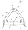
- Fig.3
- die in Fig. 2 dargestellte Vorrichtung in Pfeilrichtung -x- betrachtet.
- 1
- Schlepper
- 2
- Achsen
- 3
- Achsen
- 4
- Lenker
- 5
- Lenker
- 6
- Kolbenzylindereinheiten
- 7
- Kolbenzylindereinheiten
- 8
- Quertraverse
- 9
- Platte
- 10
- Platte
- 11
- Aufnahmelasche
- 12
- Querholm
- 13
- Achse
- 14
- Kolbenzylindereinheiten
- 15
- Kolbenzylindereinheiten
- 16
- Holm
- 17
- Holm
- 18
- Holm
- 19
- Koppelrahmen
- 20
- Zapfen
- 21
- Kopf
- 22
- Verstelleinheit
- 23
- Fanghaken
- 24
- Fanghaken
- 25
- Aufnahmen
- 26
- Aufnahmen
- 27
- Fanghaken
- 28
- Laschen
- 29
- Gelenke
Claims (6)
- Vorrichtung zum Kuppeln eines Antriebsfahrzeuges, insbesondere eines Schleppers mit einem von diesem zu tragenden oder zu ziehenden Gerät mit einem Koppelrahmen, der sich über eine senkrechte Achse (13) schwenkbar an einer Quertraverse abstützt, wobei die Quertraverse beidendig über zwei Lenker gehalten und jeder Lenker einendig um eine horizontale Achse am Schlepper befestigt und mittels einer hydraulischen Kolbenzylindereinheit (6,7) anheb- und absenkbar ist, und wobei der Koppelrahmen mittels einer weiteren in seinem oberen Bereich angreifenden und mit dem Schlepper verbundenen längenveränderbaren Einheit (22) neigungseinstellbar ist,
dadurch gekennzeichnet, daß
die Quertraverse (8) in Gelenken (29) mit den Lenkern (4, 5) verbunden ist, wobei mit der Quertraverse (8) mittig eine sich vom Schlepper weg erstreckende relativ schmale Lasche (11) fest verbunden ist, die an ihrem der Quertraverse (8) abgewandten Ende die senkrechte Achse (13) aufnimmt, an der der Koppelrahmen (19) schwenkbar befestigt ist, wobei die senkrechte Achse (13) von der Quertraverse (8) absteht. - Vorrichtung nach Anspruch 1,
dadurch gekennzeichnet, daß
der Abstand der Schwenkachse (13) zur Quertraverse (8) so gewählt ist, dass der Koppelrahmen (19) und die mit ihm verbindbaren Geräte verschwenkbar ist. - Vorrichtung nach Anspruch 1,
dadurch gekennzeichnet, daß seitlich von der Lasche (11) mindestens eine hydraulische, längenveränderbare, sich mit ihren Enden an der Quertraverse (8) und dem Querhom (12) des Koppelrahmens (19) abstützende Kolbenzylindereinheit (14, 15) vorgesehen ist. - Vorrichtung nach Anspruch 1,
dadurch gekennzeichnet, daß die Lasche (11) aus zwei mit Abstand übereinanderangeordneten Platten (9) und (10) besteht, die zwischen sich den unteren Querholm (12) des Koppelrahmens (19) über eine Achse (13) aufnehmen. - Vorrichtung nach einem oder mehreren der vorgenannten Ansprüche 1 bis 4,
dadurch gekennzeichnet, daß der Koppelrahmen (19) drei vorkragende Fanghaken (23, 24 und 27) zur Ankopplung eines Anbaugerätes oder dergleichen aufweist, von denen einer (27) im oberen Bereich des Koppelrahmens (19) und die beiden anderen (23 und 24) an je einem Ende des Querholms 12 vorgesehen sind. - Vorrichtung nach Anspruch 5,
dadurch gekennzeichnet, daß die Fanghaken (23 und 24) in mit dem unteren Querholm (12) verbundenen Aufnahmen (25 und 26) höheneinstellbar gelagert sind.
Applications Claiming Priority (2)
| Application Number | Priority Date | Filing Date | Title |
|---|---|---|---|
| DE19846341 | 1998-10-08 | ||
| DE19846341A DE19846341A1 (de) | 1998-10-08 | 1998-10-08 | Antriebsfahrzeug mit Koppelrahmen zur Aufnahme von Arbeitsgeräten |
Publications (2)
| Publication Number | Publication Date |
|---|---|
| EP0992371A1 EP0992371A1 (de) | 2000-04-12 |
| EP0992371B1 true EP0992371B1 (de) | 2003-09-17 |
Family
ID=7883792
Family Applications (1)
| Application Number | Title | Priority Date | Filing Date |
|---|---|---|---|
| EP99119752A Expired - Lifetime EP0992371B1 (de) | 1998-10-08 | 1999-10-04 | Vorrichtung zum Kuppeln eines Antriebsfahrzeuges mit einem Koppelrahmen zur Aufnahme von Arbeitsgeräten |
Country Status (6)
| Country | Link |
|---|---|
| EP (1) | EP0992371B1 (de) |
| AT (1) | ATE249943T1 (de) |
| DE (2) | DE19846341A1 (de) |
| DK (1) | DK0992371T3 (de) |
| RU (1) | RU2226325C2 (de) |
| UA (1) | UA58545C2 (de) |
Cited By (1)
| Publication number | Priority date | Publication date | Assignee | Title |
|---|---|---|---|---|
| CN105939596A (zh) * | 2014-07-09 | 2016-09-14 | 格兰集团营运挪威股份有限公司 | 在三点联接机具上用于连接到工具载运机的铰接联结架 |
Families Citing this family (6)
| Publication number | Priority date | Publication date | Assignee | Title |
|---|---|---|---|---|
| DE102004014797A1 (de) * | 2004-03-24 | 2005-10-13 | Claas Selbstfahrende Erntemaschinen Gmbh | Dreipunktaufhängung für eine Arbeitsmaschine |
| US8496070B2 (en) * | 2010-09-20 | 2013-07-30 | Deere & Company | Folding hitch lift arm |
| RU2473448C2 (ru) * | 2011-04-28 | 2013-01-27 | Валерий Александрович Верещагин | Автомобильный прицеп |
| DE202011108409U1 (de) | 2011-11-29 | 2013-03-01 | Josef Kotte Landtechnik Gmbh & Co. Kg | Zugfahrzeug mit schwenkbarem Koppelrahmen |
| RU2680451C1 (ru) * | 2018-05-04 | 2019-02-21 | Федеральное государственное бюджетное научное учреждение Федеральный научный агроинженерный центр ВИМ (ФГБНУ ФНАЦ ВИМ) | Гидромеханическое следящее навесное устройство |
| CN119073035A (zh) * | 2023-12-11 | 2024-12-06 | 新疆农业大学 | 大型牵引式农机具柔性调偏装置及控制系统 |
Family Cites Families (10)
| Publication number | Priority date | Publication date | Assignee | Title |
|---|---|---|---|---|
| US3432184A (en) * | 1967-07-10 | 1969-03-11 | United States Steel Corp | Power actuated tractor hitch |
| FR2379242A1 (fr) * | 1977-02-07 | 1978-09-01 | Delfosse Charles | Nouvel attelage de machine agricole |
| FR2454255A1 (fr) * | 1979-04-19 | 1980-11-14 | Durnerin Charles | Perfectionnements aux engins pour le defrichement du sol ou travail similaire |
| US4572315A (en) * | 1984-02-09 | 1986-02-25 | Valley Engineering, Inc. | Power hitch |
| GB2185872A (en) * | 1986-02-04 | 1987-08-05 | Harpley Engineering Ltd | Agricultural implement and method of cropping |
| SU1514258A1 (ru) * | 1986-06-16 | 1989-10-15 | Voronezh Lesotekh Inst | Ceльckoxoзяйctbehhый aгpeгat |
| DE3739291A1 (de) * | 1987-11-20 | 1989-06-01 | Rauch Landmaschfab Gmbh | Vorrichtung zum anbau landwirtschaftlicher verteilermaschinen an dem dreipunktgestaenge eines fahrzeugs |
| SU1535403A2 (ru) * | 1988-04-26 | 1990-01-15 | Литовский Научно-Исследовательский Институт Механизации И Электрификации Сельского Хозяйства | Широкозахватна сцепка дл сельскохоз йственных орудий |
| DE4132889A1 (de) | 1990-10-05 | 1992-04-09 | Erwin Roeder | Vorrichtung zum kuppeln eines antriebsfahrzeugs, insbes. schleppers, mit einem vom antriebsfahrzeug zu tragenden oder zu ziehenden geraet, wie anbaugeraet oder anhaenger |
| DE29502693U1 (de) * | 1995-02-18 | 1995-04-13 | Gießler, Matthias, Dipl.-Ing. (FH), 77933 Lahr | Tragvorrichtung für Anbaugeräte an Arbeitsfahrzeuge |
-
1998
- 1998-10-08 DE DE19846341A patent/DE19846341A1/de not_active Withdrawn
-
1999
- 1999-10-04 AT AT99119752T patent/ATE249943T1/de not_active IP Right Cessation
- 1999-10-04 DK DK99119752T patent/DK0992371T3/da active
- 1999-10-04 DE DE59906999T patent/DE59906999D1/de not_active Expired - Lifetime
- 1999-10-04 EP EP99119752A patent/EP0992371B1/de not_active Expired - Lifetime
- 1999-10-07 UA UA99105473A patent/UA58545C2/uk unknown
- 1999-10-07 RU RU99121147/12A patent/RU2226325C2/ru not_active IP Right Cessation
Cited By (2)
| Publication number | Priority date | Publication date | Assignee | Title |
|---|---|---|---|---|
| CN105939596A (zh) * | 2014-07-09 | 2016-09-14 | 格兰集团营运挪威股份有限公司 | 在三点联接机具上用于连接到工具载运机的铰接联结架 |
| CN105939596B (zh) * | 2014-07-09 | 2018-06-15 | 格兰集团营运挪威股份有限公司 | 在三点联接机具上用于连接到工具载运机的铰接联结架 |
Also Published As
| Publication number | Publication date |
|---|---|
| RU2226325C2 (ru) | 2004-04-10 |
| DK0992371T3 (da) | 2004-02-02 |
| DE19846341A1 (de) | 2000-04-13 |
| ATE249943T1 (de) | 2003-10-15 |
| DE59906999D1 (de) | 2003-10-23 |
| EP0992371A1 (de) | 2000-04-12 |
| UA58545C2 (uk) | 2003-08-15 |
Similar Documents
| Publication | Publication Date | Title |
|---|---|---|
| EP2408971B1 (de) | Auswechselbare kehrbürsteneinrichtung und kehrmaschine mit einer derartigen kehrbürsteneinrichtung | |
| EP0271645A1 (de) | Schneepflug | |
| EP0063774B1 (de) | Geräteanbauvorrichtung für ein landwirtschaftliches Arbeitsfahrzeug | |
| EP0063167B1 (de) | Land- und/oder bauwirtschaftlich nutzbares Kraftfahrzeug mit frontseitiger Geräteanbauvorrichtung | |
| DE3105639A1 (de) | "geraetekombination fuer die landwirtschaft" | |
| EP0992371A1 (de) | Antriebsfahrzeug mit Koppelrahmen zur Aufnahme von Arbeitsgeräten | |
| CH665237A5 (en) | Bulldozer blade mounting - has double acting rams with linkage on horizontal vehicle axis to blade end hinge | |
| EP0587175A1 (de) | Schneepflug | |
| DE19820377C1 (de) | Arbeitsfahrzeug mit kippbarer Fahrerplattform und Kippvorrichtung | |
| DE3914423C2 (de) | Zubehör für Anbaugeräte | |
| DE1657501B1 (de) | An einem Ackerschlepper anbaubare Spruehvorrichtung | |
| DE2160227A1 (de) | Hoehenverstellbare spritzgestaengeaufhaengung fuer fahrbare schaedlingsbekaempfungsgeraete in feldkulturen mit einem quer zur fahrtrichtung liegenden spritzgestaenge | |
| DE102008062712A1 (de) | Mähwerk mit Querfördereinrichtung | |
| DE3224269A1 (de) | Auswurfkruemmer fuer landwirtschaftliche maschinen | |
| DE10039259C2 (de) | Schneepflug | |
| EP0427149B1 (de) | Vorrichtung zum Anbau einer Landmaschine an einen Dreipunktbock | |
| DE4015862A1 (de) | Frontanbauvorrichtung an schleppern | |
| DE2615497A1 (de) | Zugdeichselanordnung, insbesondere fuer einachsige schleppergezogene landwirtschaftliche maschinen | |
| DE3031037A1 (de) | Steuervorrichtung fuer die hydraulische betaetigung eines an einem raeumfahrzeug angebauten schneepflug | |
| EP1579750B1 (de) | Dreipunktaufhängung für eine Arbeitsmaschine | |
| DE1582169A1 (de) | Erntebergungsmaschine,insbesondere Feldhaecksler | |
| DE2317263C3 (de) | Vorrichtung zum Anbau eines seitlich neben einem Ackerschlepper arbeitenden Arbeitsgerätes, insbesondere eines Feldhäckslers | |
| DE29507859U1 (de) | Frontkraftheber | |
| DE102012108229A1 (de) | Drehpflug | |
| DE102012108236A1 (de) | Drehpflug |
Legal Events
| Date | Code | Title | Description |
|---|---|---|---|
| PUAI | Public reference made under article 153(3) epc to a published international application that has entered the european phase |
Free format text: ORIGINAL CODE: 0009012 |
|
| AK | Designated contracting states |
Kind code of ref document: A1 Designated state(s): AT BE CH CY DE DK ES FI FR GB GR IE IT LI LU MC NL PT SE |
|
| AX | Request for extension of the european patent |
Free format text: AL;LT;LV;MK;RO;SI |
|
| 17P | Request for examination filed |
Effective date: 20001012 |
|
| AKX | Designation fees paid |
Free format text: AT BE CH CY DE DK ES FI FR GB GR IE IT LI LU MC NL PT SE |
|
| RTI1 | Title (correction) |
Free format text: COUPLING DEVICE FOR A VEHICLE WITH AN ATTACHMENT FRAME FOR MOUNTING WORKING IMPLEMENTS |
|
| 17Q | First examination report despatched |
Effective date: 20020828 |
|
| GRAH | Despatch of communication of intention to grant a patent |
Free format text: ORIGINAL CODE: EPIDOS IGRA |
|
| RTI1 | Title (correction) |
Free format text: COUPLING DEVICE FOR A VEHICLE WITH AN ATTACHMENT FRAME FOR MOUNTING WORKING IMPLEMENTS |
|
| GRAS | Grant fee paid |
Free format text: ORIGINAL CODE: EPIDOSNIGR3 |
|
| GRAA | (expected) grant |
Free format text: ORIGINAL CODE: 0009210 |
|
| AK | Designated contracting states |
Kind code of ref document: B1 Designated state(s): AT BE CH CY DE DK ES FI FR GB GR IE IT LI LU MC NL PT SE |
|
| PG25 | Lapsed in a contracting state [announced via postgrant information from national office to epo] |
Ref country code: NL Free format text: LAPSE BECAUSE OF FAILURE TO SUBMIT A TRANSLATION OF THE DESCRIPTION OR TO PAY THE FEE WITHIN THE PRESCRIBED TIME-LIMIT Effective date: 20030917 Ref country code: IE Free format text: LAPSE BECAUSE OF FAILURE TO SUBMIT A TRANSLATION OF THE DESCRIPTION OR TO PAY THE FEE WITHIN THE PRESCRIBED TIME-LIMIT Effective date: 20030917 Ref country code: FI Free format text: LAPSE BECAUSE OF FAILURE TO SUBMIT A TRANSLATION OF THE DESCRIPTION OR TO PAY THE FEE WITHIN THE PRESCRIBED TIME-LIMIT Effective date: 20030917 |
|
| REG | Reference to a national code |
Ref country code: GB Ref legal event code: FG4D Free format text: NOT ENGLISH |
|
| REG | Reference to a national code |
Ref country code: CH Ref legal event code: EP |
|
| PG25 | Lapsed in a contracting state [announced via postgrant information from national office to epo] |
Ref country code: LU Free format text: LAPSE BECAUSE OF NON-PAYMENT OF DUE FEES Effective date: 20031004 Ref country code: CY Free format text: LAPSE BECAUSE OF FAILURE TO SUBMIT A TRANSLATION OF THE DESCRIPTION OR TO PAY THE FEE WITHIN THE PRESCRIBED TIME-LIMIT Effective date: 20031004 Ref country code: AT Free format text: LAPSE BECAUSE OF NON-PAYMENT OF DUE FEES Effective date: 20031004 |
|
| REF | Corresponds to: |
Ref document number: 59906999 Country of ref document: DE Date of ref document: 20031023 Kind code of ref document: P |
|
| REG | Reference to a national code |
Ref country code: IE Ref legal event code: FG4D Free format text: GERMAN |
|
| PG25 | Lapsed in a contracting state [announced via postgrant information from national office to epo] |
Ref country code: MC Free format text: LAPSE BECAUSE OF NON-PAYMENT OF DUE FEES Effective date: 20031031 Ref country code: LI Free format text: LAPSE BECAUSE OF NON-PAYMENT OF DUE FEES Effective date: 20031031 Ref country code: CH Free format text: LAPSE BECAUSE OF NON-PAYMENT OF DUE FEES Effective date: 20031031 Ref country code: BE Free format text: LAPSE BECAUSE OF NON-PAYMENT OF DUE FEES Effective date: 20031031 |
|
| GBT | Gb: translation of ep patent filed (gb section 77(6)(a)/1977) |
Effective date: 20031117 |
|
| PG25 | Lapsed in a contracting state [announced via postgrant information from national office to epo] |
Ref country code: SE Free format text: LAPSE BECAUSE OF FAILURE TO SUBMIT A TRANSLATION OF THE DESCRIPTION OR TO PAY THE FEE WITHIN THE PRESCRIBED TIME-LIMIT Effective date: 20031217 Ref country code: GR Free format text: LAPSE BECAUSE OF FAILURE TO SUBMIT A TRANSLATION OF THE DESCRIPTION OR TO PAY THE FEE WITHIN THE PRESCRIBED TIME-LIMIT Effective date: 20031217 |
|
| PG25 | Lapsed in a contracting state [announced via postgrant information from national office to epo] |
Ref country code: PT Free format text: LAPSE BECAUSE OF FAILURE TO SUBMIT A TRANSLATION OF THE DESCRIPTION OR TO PAY THE FEE WITHIN THE PRESCRIBED TIME-LIMIT Effective date: 20031226 |
|
| PG25 | Lapsed in a contracting state [announced via postgrant information from national office to epo] |
Ref country code: ES Free format text: LAPSE BECAUSE OF FAILURE TO SUBMIT A TRANSLATION OF THE DESCRIPTION OR TO PAY THE FEE WITHIN THE PRESCRIBED TIME-LIMIT Effective date: 20031228 |
|
| REG | Reference to a national code |
Ref country code: DK Ref legal event code: T3 |
|
| NLV1 | Nl: lapsed or annulled due to failure to fulfill the requirements of art. 29p and 29m of the patents act | ||
| REG | Reference to a national code |
Ref country code: IE Ref legal event code: FD4D |
|
| BERE | Be: lapsed |
Owner name: *CLAAS SELBSTFAHRENDE ERNTEMASCHINEN G.M.B.H. Effective date: 20031031 |
|
| REG | Reference to a national code |
Ref country code: CH Ref legal event code: PL |
|
| ET | Fr: translation filed | ||
| PLBE | No opposition filed within time limit |
Free format text: ORIGINAL CODE: 0009261 |
|
| STAA | Information on the status of an ep patent application or granted ep patent |
Free format text: STATUS: NO OPPOSITION FILED WITHIN TIME LIMIT |
|
| 26N | No opposition filed |
Effective date: 20040618 |
|
| REG | Reference to a national code |
Ref country code: DE Ref legal event code: R084 Ref document number: 59906999 Country of ref document: DE |
|
| REG | Reference to a national code |
Ref country code: DE Ref legal event code: R084 Ref document number: 59906999 Country of ref document: DE Effective date: 20140718 |
|
| PGFP | Annual fee paid to national office [announced via postgrant information from national office to epo] |
Ref country code: DK Payment date: 20141027 Year of fee payment: 16 |
|
| PGFP | Annual fee paid to national office [announced via postgrant information from national office to epo] |
Ref country code: GB Payment date: 20141024 Year of fee payment: 16 |
|
| REG | Reference to a national code |
Ref country code: FR Ref legal event code: PLFP Year of fee payment: 17 |
|
| PGFP | Annual fee paid to national office [announced via postgrant information from national office to epo] |
Ref country code: DE Payment date: 20150701 Year of fee payment: 17 Ref country code: IT Payment date: 20151026 Year of fee payment: 17 |
|
| PGFP | Annual fee paid to national office [announced via postgrant information from national office to epo] |
Ref country code: FR Payment date: 20151026 Year of fee payment: 17 |
|
| REG | Reference to a national code |
Ref country code: DK Ref legal event code: EBP Effective date: 20151031 |
|
| GBPC | Gb: european patent ceased through non-payment of renewal fee |
Effective date: 20151004 |
|
| PG25 | Lapsed in a contracting state [announced via postgrant information from national office to epo] |
Ref country code: GB Free format text: LAPSE BECAUSE OF NON-PAYMENT OF DUE FEES Effective date: 20151004 |
|
| PG25 | Lapsed in a contracting state [announced via postgrant information from national office to epo] |
Ref country code: DK Free format text: LAPSE BECAUSE OF NON-PAYMENT OF DUE FEES Effective date: 20151031 |
|
| REG | Reference to a national code |
Ref country code: DE Ref legal event code: R119 Ref document number: 59906999 Country of ref document: DE |
|
| REG | Reference to a national code |
Ref country code: FR Ref legal event code: ST Effective date: 20170630 |
|
| PG25 | Lapsed in a contracting state [announced via postgrant information from national office to epo] |
Ref country code: FR Free format text: LAPSE BECAUSE OF NON-PAYMENT OF DUE FEES Effective date: 20161102 Ref country code: DE Free format text: LAPSE BECAUSE OF NON-PAYMENT OF DUE FEES Effective date: 20170503 |
|
| PG25 | Lapsed in a contracting state [announced via postgrant information from national office to epo] |
Ref country code: IT Free format text: LAPSE BECAUSE OF NON-PAYMENT OF DUE FEES Effective date: 20161004 |