EP0992298B1 - Trennvorrichtung zur Trennung der äusseren Schlingen von in Schlingensammelvorrichtungen gebildeten Walzdrahtbunden - Google Patents
Trennvorrichtung zur Trennung der äusseren Schlingen von in Schlingensammelvorrichtungen gebildeten Walzdrahtbunden Download PDFInfo
- Publication number
- EP0992298B1 EP0992298B1 EP99117759A EP99117759A EP0992298B1 EP 0992298 B1 EP0992298 B1 EP 0992298B1 EP 99117759 A EP99117759 A EP 99117759A EP 99117759 A EP99117759 A EP 99117759A EP 0992298 B1 EP0992298 B1 EP 0992298B1
- Authority
- EP
- European Patent Office
- Prior art keywords
- separating
- separating device
- loops
- supports
- shears
- Prior art date
- Legal status (The legal status is an assumption and is not a legal conclusion. Google has not performed a legal analysis and makes no representation as to the accuracy of the status listed.)
- Expired - Lifetime
Links
Images


Classifications
-
- B—PERFORMING OPERATIONS; TRANSPORTING
- B21—MECHANICAL METAL-WORKING WITHOUT ESSENTIALLY REMOVING MATERIAL; PUNCHING METAL
- B21C—MANUFACTURE OF METAL SHEETS, WIRE, RODS, TUBES, PROFILES OR LIKE SEMI-MANUFACTURED PRODUCTS OTHERWISE THAN BY ROLLING; AUXILIARY OPERATIONS USED IN CONNECTION WITH METAL-WORKING WITHOUT ESSENTIALLY REMOVING MATERIAL
- B21C47/00—Winding-up, coiling or winding-off metal wire, metal band or other flexible metal material characterised by features relevant to metal processing only
- B21C47/26—Special arrangements with regard to simultaneous or subsequent treatment of the material
-
- Y—GENERAL TAGGING OF NEW TECHNOLOGICAL DEVELOPMENTS; GENERAL TAGGING OF CROSS-SECTIONAL TECHNOLOGIES SPANNING OVER SEVERAL SECTIONS OF THE IPC; TECHNICAL SUBJECTS COVERED BY FORMER USPC CROSS-REFERENCE ART COLLECTIONS [XRACs] AND DIGESTS
- Y10—TECHNICAL SUBJECTS COVERED BY FORMER USPC
- Y10S—TECHNICAL SUBJECTS COVERED BY FORMER USPC CROSS-REFERENCE ART COLLECTIONS [XRACs] AND DIGESTS
- Y10S83/00—Cutting
- Y10S83/907—Coiled wire cutting
-
- Y—GENERAL TAGGING OF NEW TECHNOLOGICAL DEVELOPMENTS; GENERAL TAGGING OF CROSS-SECTIONAL TECHNOLOGIES SPANNING OVER SEVERAL SECTIONS OF THE IPC; TECHNICAL SUBJECTS COVERED BY FORMER USPC CROSS-REFERENCE ART COLLECTIONS [XRACs] AND DIGESTS
- Y10—TECHNICAL SUBJECTS COVERED BY FORMER USPC
- Y10T—TECHNICAL SUBJECTS COVERED BY FORMER US CLASSIFICATION
- Y10T83/00—Cutting
- Y10T83/647—With means to convey work relative to tool station
- Y10T83/6584—Cut made parallel to direction of and during work movement
- Y10T83/6587—Including plural, laterally spaced tools
Definitions
- the invention relates to a separating device for separating the outer loops of wire rod coils formed in loop collecting devices, which in successive Hang the transport hook of a hook transport track (see e.g. JP-A-60 087924).
- the outer, i.e. some of the first and last loops of the covenant exhibit thermal engineering and not with regard to their diameter tolerances the required qualities are often bent and must therefore be processed before the federal government be separated from the federal government.
- the object of the invention is based on this manual mode of operation to create a mechanically operating disconnect device that loops the outer secure both ends of the bundle hanging on the hook of the hook conveyor cuts off and the cut ends eliminated.
- This task is arranged in the direction of both sides of the hook transport path on the ring end faces of the federal government and carriers that can be moved away from them, and on these arranged separating scissors solved on these supports in guides in vertical Levels are adjustable.
- the carrier can be approximately radial to the circumference of the bundles movable wedge elements that can be inserted and removed between the individual loops of the federal government be assigned. Furthermore, several can be arranged on the side of the carrier approximately horizontally in the direction of the ring end faces of the bundles, in and under the loops movable and lifting and lowerable rod elements are provided. Between Both carriers can, below the federal government hanging on the transport hook, a receiving device for the loops of the federal government severed by the shears be provided. Two or more shears can be angled to each other on the one or the other carrier can be arranged, and cutting shears and wedge elements can be arranged side by side connected to the housing. The front ends of the rod elements advantageously have a hook.
- the receiving device can consist of arranged parallel to each other and funnel-shaped on both sides of the hook transport path slabs inclined to the vertical. These plates expediently Through slots for the rod elements.
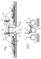
- the side are by means of transport hooks 1 arranged hook conveyor track arranged 2 and 3, respectively with the help of the hydraulic pushing devices 4 and 5 here, in the direction of the drawing Double arrow S horizontally moved towards and away from each other can be.
- the beams 2 and 3 have both the transport track and the end faces of the Confederation 6 facing cantilevers 2a and 3a on their facing each other End faces have guides 7 and 8, in which pairs of scissors 9 or 10 approximately are radially displaceable to the ring circumference of the federal government.
- the respective cutting scissors the pair of scissors 9 or 10 asymmetrical on both sides of the transport hook 1 arranged to each other (Fig.2).
- a receiving device 11 for provided by the pairs of scissors 9 and 10 cut loops 6a the consists of a pair of funnel-shaped plates 11a and 11b bent from one another.
- the respective pairs of cutting scissors 9 and 10 in the direction of the Collar 6 and movable away from this driven by a displacement motor 14 Wedge elements and each funnel-shaped bent plate pairs 17 for detection and Leadership of the federal government 6 provided.
- the separators work in such a way that the two carriers 2 and 3 with the help of Thrust devices 4 and 5 against each other in the direction of the end faces of the in the Fig. 1 reproduced position of the hanging on the support hook 1 federal 6 from the in Fig. 1, right, reproduced position in the position shown on the left in this figure be moved.
- the pair of guide plates 17 detects the collar and the wedge elements 15 (Fig. 5) is moved between the outer loops 6a of the collar 6 and pushes some of these loops out from the front of collar 6. Subsequently the two pair of cutting scissors 9 make the separating cuts.
- the two carriers 2 and 3 after implementation the separating cuts on both ends of the federal government 6 through the pairs of cutting scissors 9 or 10 away from the end faces of the federal government 6 in the positions shown driven, and the rod elements 12 by means of the parallelogram supports 13 against the End faces of the federal government 6 and the respective outer loops 6a moved while being raised and moved back again.
Landscapes
- Engineering & Computer Science (AREA)
- Mechanical Engineering (AREA)
- Winding, Rewinding, Material Storage Devices (AREA)
- Load-Engaging Elements For Cranes (AREA)
- Wire Processing (AREA)
- Chain Conveyers (AREA)
- Accessories And Tools For Shearing Machines (AREA)
Description
- Figur 1
- die Trennvorrichtung von der Seite gesehen in schematischer Darstellung,
- Figur 2
- die Ansicht eines Schnittes nach der Linie A-A durch Fig. 1,
- Figur 3
- eine weitere Ausbildungsform der Vorrichtung nach Fig. 1,
- Figur 4
- die Seitenansicht eines Schnittes nach der Linie B-B durch Fig. 3,
- Figur 5
- eine Einzelheit aus Fig. 1 in vergrößertem Maßstab, und
- Figur 6
- eine Einzelheit aus Fig.3 in vergrößertem Maßstab.
- 1
- Transporthaken
- 2
- Träger
- 2a
- Kragansatz
- 3
- Träger
- 3a
- Kragansatz
- 4
- Schubeinrichtung
- 5
- Schubeinrichtung
- 6
- Bund
- 6a
- Schlingen (des Bundes)
- 7
- Führung
- 8
- Führung
- 9
- Trennschere
- 10
- Trennschere
- 11
- Aufnahmevorrichtung
- 11a
- Platte
- 11b
- Platte
- 12
- Stangenelemente
- 12a
- Haken
- 13
- Parallelogrammstützen
- 14
- Verschiebemotor
- 15
- Keilelement
- 16
- Längsschlitze
- 17
- Leitblechpaar
Claims (8)
- Trennvorrichtung zur Trennung der äußeren Schlingen (6a) von, in Schlingensammelvorrichtungen gebildeten Walzdrahtbunden (6), die in aufeinanderfolgenden Transporthaken (1) einer Hakentransportbahn hängen,
gekennzeichnet durch
beiderseits der Hakentransportbahn angeordnete, in Richtung auf die Ringstimseiten der Bunde (6) und von diesen weg verfahrbare Träger (2; 3) und auf diesen angeordnete Trennscheren (9; 10), die auf diesen in Führungen (7) in vertikalen Ebenen verschieb- und winkelverstellbar sind. - Trennvorrichtung nach Anspruch 1,
gekennzeichnet durch
den Trägern (2; 3) zugeordnete, etwa radial zum Umfang der Bunde (6) bewegbare, von einem Verschiebemotor (14) angetriebene, zwischen die einzelnen Schlingen (6a) des Bundes (6) ein- und ausbringbare Keilelemente (15). - Trennvorrichtung nach den Ansprüchen 1 und/oder 2,
gekennzeichnet durch
mehrere, seitlich der Träger (2; 3) angeordnete, etwa in Richtung auf die Ringstirnseiten des Bundes in und unter die Schlingen (6a) beweg- und heb- sowie senkbare Stangenelemente (12). - Trennvorrichtung nach einem oder mehreren der Ansprüche 1 bis 3,
gekennzeichnet durch
eine, zwischen beiden Trägern (2; 3), unterhalb des hängenden Bundes (6) angeordnete Aufnahmevorrichtung (11) für die von den Trennscheren (9; 10) abgetrennten Schlingen (6a) des Bundes (6). - Trennvorrichtung nach einem oder mehreren der Ansprüche 1 bis 4,
gekennzeichnet durch
je zwei oder mehr auf einem Träger (2; 3) winklig zueinander angeordnete Trennscheren (9 bzw. 10). - Trennvorrichtung nach Anspruch 2,
dadurch gekennzeichnet, daß Trennschere (9; 10) und Verschiebemotor (14) gehäuseverbunden ausgebildet und angeordnet sind. - Trennvorrichtung nach Anspruch 3,
dadurch gekennzeichnet, daß die vorderen Enden der Stangenelemente (12) als Haken (12a) ausgebildet sind. - Trennvorrichtung nach den Ansprüchen 3 und/oder 4,
dadurch gekennzeichnet, daß die Aufnahmevorrichtung (11) aus beiderseits der Hakentransportbahn angeordneten, parallel zueinander und trichterförmig geneigt zur Vertikalen liegenden Platten (11a, 11b) besteht, die Durchgangsschlitze (16) für die Stangenelemente (12) aufweisen.
Applications Claiming Priority (2)
| Application Number | Priority Date | Filing Date | Title |
|---|---|---|---|
| DE19846101 | 1998-10-07 | ||
| DE19846101A DE19846101C1 (de) | 1998-10-07 | 1998-10-07 | Trennvorrichtung zur Trennung der äußeren Schlingen von in Schlingensammelvorrichtungen gebildeten Walzdrahtbunden |
Publications (3)
| Publication Number | Publication Date |
|---|---|
| EP0992298A2 EP0992298A2 (de) | 2000-04-12 |
| EP0992298A3 EP0992298A3 (de) | 2001-08-29 |
| EP0992298B1 true EP0992298B1 (de) | 2004-01-28 |
Family
ID=7883635
Family Applications (1)
| Application Number | Title | Priority Date | Filing Date |
|---|---|---|---|
| EP99117759A Expired - Lifetime EP0992298B1 (de) | 1998-10-07 | 1999-09-09 | Trennvorrichtung zur Trennung der äusseren Schlingen von in Schlingensammelvorrichtungen gebildeten Walzdrahtbunden |
Country Status (4)
| Country | Link |
|---|---|
| US (1) | US6227091B1 (de) |
| EP (1) | EP0992298B1 (de) |
| AT (1) | ATE258474T1 (de) |
| DE (2) | DE19846101C1 (de) |
Families Citing this family (4)
| Publication number | Priority date | Publication date | Assignee | Title |
|---|---|---|---|---|
| US20190291168A1 (en) * | 2018-03-20 | 2019-09-26 | Primetals Technologies USA LLC | Automated wire rod trimming station |
| US11618069B2 (en) | 2018-03-20 | 2023-04-04 | Primetals Technologies USA LLC | Automated wire rod trimming station and sample quality evaluation |
| EP4008447B1 (de) | 2020-12-04 | 2024-04-03 | Yeminy Inc. | Automatische schneidvorrichtung für drahtspulen |
| EP4275807B1 (de) | 2022-05-13 | 2025-01-29 | Yeminy Inc. | Automatische schneidvorrichtung für drahtspulen |
Family Cites Families (7)
| Publication number | Priority date | Publication date | Assignee | Title |
|---|---|---|---|---|
| DE1752196A1 (de) * | 1968-04-18 | 1971-05-13 | Schloemann Ag | Verfahren und Vorrichtung zum Unterteilen einer Windungslage |
| DE2102684C3 (de) * | 1971-01-21 | 1980-02-28 | Friedrich Kocks Gmbh & Co, 4000 Duesseldorf | Vorrichtung zum Durchtrennen von Walzdraht |
| US3838617A (en) * | 1973-08-29 | 1974-10-01 | Penetred Corp | Art of shearing a helical coil |
| DE2915716C2 (de) * | 1979-04-19 | 1983-03-24 | Fried. Krupp Gmbh, 4300 Essen | Verfahren zur Beseitigung des Vorder- und Hinterabschnitts von Walzdraht und Vorrichtung zur Durchführung des Verfahrens |
| JPS6087924A (ja) * | 1983-10-21 | 1985-05-17 | Nippon Steel Corp | 線材端末クロツプ切断処理方法 |
| GB9004902D0 (en) * | 1990-03-05 | 1990-05-02 | Ashlon Eng Ltd | The manufacture of metal rod |
| JPH08309435A (ja) * | 1995-05-16 | 1996-11-26 | Nkk Corp | コイル状金属帯の切断装置 |
-
1998
- 1998-10-07 DE DE19846101A patent/DE19846101C1/de not_active Expired - Fee Related
-
1999
- 1999-09-09 EP EP99117759A patent/EP0992298B1/de not_active Expired - Lifetime
- 1999-09-09 DE DE59908401T patent/DE59908401D1/de not_active Expired - Fee Related
- 1999-09-09 AT AT99117759T patent/ATE258474T1/de not_active IP Right Cessation
- 1999-10-06 US US09/413,359 patent/US6227091B1/en not_active Expired - Fee Related
Also Published As
| Publication number | Publication date |
|---|---|
| US6227091B1 (en) | 2001-05-08 |
| EP0992298A3 (de) | 2001-08-29 |
| DE59908401D1 (de) | 2004-03-04 |
| ATE258474T1 (de) | 2004-02-15 |
| DE19846101C1 (de) | 2000-08-31 |
| EP0992298A2 (de) | 2000-04-12 |
Similar Documents
| Publication | Publication Date | Title |
|---|---|---|
| DE112017000159B4 (de) | Vollautomatische Magnetring-Wickelmaschine | |
| DE2102684C3 (de) | Vorrichtung zum Durchtrennen von Walzdraht | |
| DE2260510B2 (de) | Verfahren und Vorrichtung zum Entfernen von Kuppelgliedern aus einem eine Reißverschlußkette bildenden Tragbandpaar | |
| DE2100869C3 (de) | Einrichtung zum Auftrennen und Entfernen von Walzblechbunde zusammenhaltenden Bindebändern | |
| EP1022222A2 (de) | Vorrichtung zum Entfernen von Bindeband von mit Bindeband umreiften Gegenständen, insbesondere Coils | |
| DE2051354C3 (de) | Vorrichtung zum Zuführen von Längsdrähten zu Gitterschweißmaschinen | |
| DE19846101C1 (de) | Trennvorrichtung zur Trennung der äußeren Schlingen von in Schlingensammelvorrichtungen gebildeten Walzdrahtbunden | |
| DE1752196A1 (de) | Verfahren und Vorrichtung zum Unterteilen einer Windungslage | |
| DE2838155C3 (de) | Förderer zum Transportieren von Drahtwindungen | |
| DE2830333C2 (de) | Vorrichtung zum lagerichtigen Transport von Bandanfängen längsgeteilter Metallbänder | |
| WO2002070164A1 (de) | Vorrichtung zum querteilen von metallbändern | |
| DE2414962A1 (de) | Buendel-formvorrichtung | |
| DE2807837A1 (de) | Tierkoerperzerlege-einrichtung fuer ein schlachthaus | |
| DE19533415C1 (de) | Mattentransporteur | |
| DE3019152C2 (de) | Walzbandbundbeförderung | |
| EP1067073B1 (de) | Vorrichtung zum Separieren von nebeneinander liegend geförderten, insbesondere aus Metall bestehenden Streifen | |
| DE2446179A1 (de) | Verfahren zum laufenden verschweissen unmittelbar aufeinanderfolgender kettenglieder unter verschwenken der zu schweissenden kettenglieder und kettenschweissmaschine zur durchfuehrung des verfahrens | |
| DE69429921T2 (de) | Werkstückpressvorrichtung für variablen Aufbau mit vorbestimmten Schritten für Abkantpressen | |
| DE1261469B (de) | Verfahren und Vorrichtung zum Answechseln der Vertikalwalzen von Universal-Walzwerken mit ihren Einbaustuecken | |
| DE3018402A1 (de) | Vorrichtung zum mehrfachen umreifen von coils | |
| DE2556220B1 (de) | Verfahren zum ausfaechern eines rohrringbundes und vorrichtung zum ausueben des verfahrens | |
| DE2920310C2 (de) | Anordnung zum Zusammenlegen von Rohgummibahn-Abschnitten im Zuge der Herstellung von Gummimatten u.dgl | |
| EP0016748A1 (de) | Stütz- und Führungsgerüst für eine Bogenstranggiessanlage | |
| DE3602465A1 (de) | Vorrichtung zum teilen und zur probeentnahme von drahtwindungsstraengen | |
| DE19908336C2 (de) | Verfahren und Vorrichtung zum Wechseln von Einloch- oder Mehrloch-Führungen an Strangpressen |
Legal Events
| Date | Code | Title | Description |
|---|---|---|---|
| PUAI | Public reference made under article 153(3) epc to a published international application that has entered the european phase |
Free format text: ORIGINAL CODE: 0009012 |
|
| 17P | Request for examination filed |
Effective date: 19990928 |
|
| AK | Designated contracting states |
Kind code of ref document: A2 Designated state(s): AT BE CH CY DE DK ES FI FR GB GR IE IT LI LU MC NL PT SE |
|
| AX | Request for extension of the european patent |
Free format text: AL;LT;LV;MK;RO;SI |
|
| RAP1 | Party data changed (applicant data changed or rights of an application transferred) |
Owner name: SMS DEMAG AG |
|
| PUAL | Search report despatched |
Free format text: ORIGINAL CODE: 0009013 |
|
| AK | Designated contracting states |
Kind code of ref document: A3 Designated state(s): AT BE CH CY DE DK ES FI FR GB GR IE IT LI LU MC NL PT SE |
|
| AX | Request for extension of the european patent |
Free format text: AL;LT;LV;MK;RO;SI |
|
| AKX | Designation fees paid |
Free format text: AT BE CH CY DE DK ES FI FR GB GR IE IT LI LU MC NL PT SE |
|
| GRAP | Despatch of communication of intention to grant a patent |
Free format text: ORIGINAL CODE: EPIDOSNIGR1 |
|
| GRAS | Grant fee paid |
Free format text: ORIGINAL CODE: EPIDOSNIGR3 |
|
| GRAA | (expected) grant |
Free format text: ORIGINAL CODE: 0009210 |
|
| AK | Designated contracting states |
Kind code of ref document: B1 Designated state(s): AT BE CH CY DE DK ES FI FR GB GR IE IT LI LU MC NL PT SE |
|
| PG25 | Lapsed in a contracting state [announced via postgrant information from national office to epo] |
Ref country code: NL Free format text: LAPSE BECAUSE OF FAILURE TO SUBMIT A TRANSLATION OF THE DESCRIPTION OR TO PAY THE FEE WITHIN THE PRESCRIBED TIME-LIMIT Effective date: 20040128 Ref country code: IE Free format text: LAPSE BECAUSE OF FAILURE TO SUBMIT A TRANSLATION OF THE DESCRIPTION OR TO PAY THE FEE WITHIN THE PRESCRIBED TIME-LIMIT Effective date: 20040128 Ref country code: FR Free format text: LAPSE BECAUSE OF FAILURE TO SUBMIT A TRANSLATION OF THE DESCRIPTION OR TO PAY THE FEE WITHIN THE PRESCRIBED TIME-LIMIT Effective date: 20040128 Ref country code: FI Free format text: LAPSE BECAUSE OF FAILURE TO SUBMIT A TRANSLATION OF THE DESCRIPTION OR TO PAY THE FEE WITHIN THE PRESCRIBED TIME-LIMIT Effective date: 20040128 Ref country code: CY Free format text: LAPSE BECAUSE OF FAILURE TO SUBMIT A TRANSLATION OF THE DESCRIPTION OR TO PAY THE FEE WITHIN THE PRESCRIBED TIME-LIMIT Effective date: 20040128 |
|
| REG | Reference to a national code |
Ref country code: GB Ref legal event code: FG4D Free format text: NOT ENGLISH |
|
| REG | Reference to a national code |
Ref country code: CH Ref legal event code: EP |
|
| REG | Reference to a national code |
Ref country code: IE Ref legal event code: FG4D Free format text: GERMAN |
|
| REF | Corresponds to: |
Ref document number: 59908401 Country of ref document: DE Date of ref document: 20040304 Kind code of ref document: P |
|
| REG | Reference to a national code |
Ref country code: SE Ref legal event code: TRGR |
|
| PG25 | Lapsed in a contracting state [announced via postgrant information from national office to epo] |
Ref country code: GR Free format text: LAPSE BECAUSE OF FAILURE TO SUBMIT A TRANSLATION OF THE DESCRIPTION OR TO PAY THE FEE WITHIN THE PRESCRIBED TIME-LIMIT Effective date: 20040428 Ref country code: DK Free format text: LAPSE BECAUSE OF FAILURE TO SUBMIT A TRANSLATION OF THE DESCRIPTION OR TO PAY THE FEE WITHIN THE PRESCRIBED TIME-LIMIT Effective date: 20040428 |
|
| PG25 | Lapsed in a contracting state [announced via postgrant information from national office to epo] |
Ref country code: ES Free format text: LAPSE BECAUSE OF FAILURE TO SUBMIT A TRANSLATION OF THE DESCRIPTION OR TO PAY THE FEE WITHIN THE PRESCRIBED TIME-LIMIT Effective date: 20040509 |
|
| GBT | Gb: translation of ep patent filed (gb section 77(6)(a)/1977) |
Effective date: 20040517 |
|
| NLV1 | Nl: lapsed or annulled due to failure to fulfill the requirements of art. 29p and 29m of the patents act | ||
| REG | Reference to a national code |
Ref country code: IE Ref legal event code: FD4D |
|
| PG25 | Lapsed in a contracting state [announced via postgrant information from national office to epo] |
Ref country code: LU Free format text: LAPSE BECAUSE OF NON-PAYMENT OF DUE FEES Effective date: 20040909 |
|
| PG25 | Lapsed in a contracting state [announced via postgrant information from national office to epo] |
Ref country code: MC Free format text: LAPSE BECAUSE OF NON-PAYMENT OF DUE FEES Effective date: 20040930 Ref country code: LI Free format text: LAPSE BECAUSE OF NON-PAYMENT OF DUE FEES Effective date: 20040930 Ref country code: CH Free format text: LAPSE BECAUSE OF NON-PAYMENT OF DUE FEES Effective date: 20040930 Ref country code: BE Free format text: LAPSE BECAUSE OF NON-PAYMENT OF DUE FEES Effective date: 20040930 |
|
| PLBE | No opposition filed within time limit |
Free format text: ORIGINAL CODE: 0009261 |
|
| STAA | Information on the status of an ep patent application or granted ep patent |
Free format text: STATUS: NO OPPOSITION FILED WITHIN TIME LIMIT |
|
| 26N | No opposition filed |
Effective date: 20041029 |
|
| EN | Fr: translation not filed | ||
| BERE | Be: lapsed |
Owner name: *SMS DEMAG A.G. Effective date: 20040930 |
|
| REG | Reference to a national code |
Ref country code: CH Ref legal event code: PL |
|
| PGFP | Annual fee paid to national office [announced via postgrant information from national office to epo] |
Ref country code: AT Payment date: 20060914 Year of fee payment: 8 |
|
| PGFP | Annual fee paid to national office [announced via postgrant information from national office to epo] |
Ref country code: GB Payment date: 20060921 Year of fee payment: 8 |
|
| PGFP | Annual fee paid to national office [announced via postgrant information from national office to epo] |
Ref country code: DE Payment date: 20060926 Year of fee payment: 8 |
|
| PGFP | Annual fee paid to national office [announced via postgrant information from national office to epo] |
Ref country code: IT Payment date: 20060930 Year of fee payment: 8 |
|
| BERE | Be: lapsed |
Owner name: *SMS DEMAG A.G. Effective date: 20040930 |
|
| PG25 | Lapsed in a contracting state [announced via postgrant information from national office to epo] |
Ref country code: PT Free format text: LAPSE BECAUSE OF NON-PAYMENT OF DUE FEES Effective date: 20040628 |
|
| PGFP | Annual fee paid to national office [announced via postgrant information from national office to epo] |
Ref country code: SE Payment date: 20060914 Year of fee payment: 8 |
|
| PG25 | Lapsed in a contracting state [announced via postgrant information from national office to epo] |
Ref country code: SE Free format text: LAPSE BECAUSE OF NON-PAYMENT OF DUE FEES Effective date: 20070910 |
|
| EUG | Se: european patent has lapsed | ||
| GBPC | Gb: european patent ceased through non-payment of renewal fee |
Effective date: 20070909 |
|
| PG25 | Lapsed in a contracting state [announced via postgrant information from national office to epo] |
Ref country code: AT Free format text: LAPSE BECAUSE OF NON-PAYMENT OF DUE FEES Effective date: 20070909 |
|
| PG25 | Lapsed in a contracting state [announced via postgrant information from national office to epo] |
Ref country code: DE Free format text: LAPSE BECAUSE OF NON-PAYMENT OF DUE FEES Effective date: 20080401 |
|
| PG25 | Lapsed in a contracting state [announced via postgrant information from national office to epo] |
Ref country code: GB Free format text: LAPSE BECAUSE OF NON-PAYMENT OF DUE FEES Effective date: 20070909 |
|
| PG25 | Lapsed in a contracting state [announced via postgrant information from national office to epo] |
Ref country code: IT Free format text: LAPSE BECAUSE OF NON-PAYMENT OF DUE FEES Effective date: 20070909 |